Configure IPSec Site-to-Site VPN on Palo Alto Networks Hardware
- Tutorial

This article is a continuation of the previous material on the features of the Palo Alto Networks equipment setup . Here we want to talk about setting up IPSec Site-to-Site VPN on Palo Alto Networks equipment and about a possible configuration option for connecting several Internet providers.
For demonstration, the standard scheme of connecting the head office to the branch will be used. In order to provide a fault-tolerant Internet connection, the head office uses the simultaneous connection of two providers: ISP-1 and ISP-2. The branch has a connection to only one provider, ISP-3. Between the firewalls PA-1 and PA-2, two tunnels are built. The tunnels operate inActive-Standby , Tunnel-1 is active, Tunnel-2 will begin to transmit traffic when Tunnel-1 fails. Tunnel-1 uses a connection to the ISP-1 Internet service provider, Tunnel-2 uses a connection to the ISP-2 Internet service provider. All IP addresses are randomly generated for demonstration purposes, and are not related to reality.

To build Site-to-Site VPN, IPSec will be used - a set of protocols for protecting data transmitted over IP. IPSec will work using the ESP (Encapsulating Security Payload) security protocol , which will provide encryption of the transmitted data.
The IPSec includes IKE(Internet Key Exchange) is the protocol responsible for negotiating SA (security associations), security parameters that are used to protect transmitted data. PAN firewalls support IKEv1 and IKEv2 .
In IKEv1 VPN, the connection is built in two stages: IKEv1 Phase 1 (IKE tunnel) and IKEv1 Phase 2 (IPSec tunnel), thus creating two tunnels, one of which serves for the exchange of service information between firewalls, the second for traffic transmission. There are two operating modes in IKEv1 Phase 1 - main mode and aggressive mode. Aggressive mode uses fewer messages and is faster, but does not support Peer Identity Protection.
IKEv2 replaces IKEv1 , and compared to IKEv1, its main advantage is less bandwidth requirements and faster SA negotiation. In IKEv2 uses less service messages (of 4), supported by the EAP protocol, and added MOBIKE mechanism to verify the availability of the feast, which creates a tunnel - Liveness the Check , which replaces Dead Peer Detection in IKEv1. If the test fails, then IKEv2 can reset the tunnel and then automatically recover as soon as possible. You can read more about the differences here .
If the tunnel is built between firewalls of different manufacturers, then there may be bugs in the implementation of IKEv2 , and for compatibility with such equipment it is possible to use IKEv1 . In other cases, it is better to use IKEv2 .
Setup steps:
• Configuring two Internet providers in Active \ Standby mode
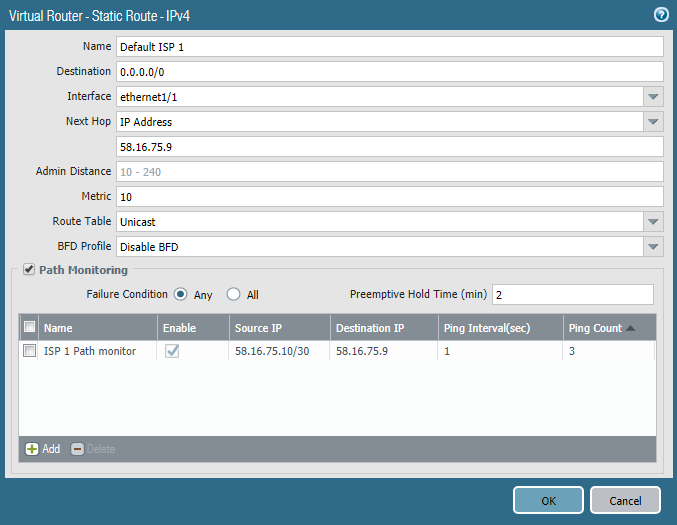
There are several ways to implement this function. One of them is to use the Path Monitoring mechanism , which has become available since PAN-OS 8.0.0. This example uses version 8.0.16. This feature is similar to IP SLA in Cisco routers. In the parameter of the static default route, sending ping packets to a specific IP address from a specific source address is configured. In this case, the ethernet1 / 1 interface pings the default gateway once per second. If there is no answer to three pings in a row, then the route is considered to be inoperative and removed from the routing table. The same route is configured in the direction of the second Internet provider, but with more metrics (it is backup). As soon as the first route is removed from the table, the firewall will start sending traffic along the second route - Fail-Over . When the first provider starts responding to pings, its route will return to the table and replace the second due to the best metric - Fail-Back. The Fail-Over process takes several seconds depending on the configured intervals, but, in any case, the process is not instantaneous, and at this time the traffic is lost. Fail-Back passes without loss of traffic. It is possible to make Fail-Over faster using BFD , if your ISP provides this option. BFD is supported starting with the PA-3000 Series and VM-100 . As the address for ping, it is better to specify not the provider’s gateway, but a public, always accessible Internet address.
• Creating a tunnel interface
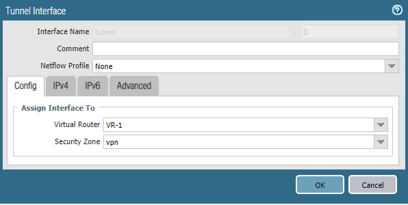
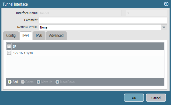
Traffic inside the tunnel is transmitted through special virtual interfaces. Each of them must be configured with an IP address from the transit network. In this example, the subnet 172.16.1.0/30 will be used for Tunnel-1, and the 172.16.2.0/30 subnet will be used for Tunnel-2.
The tunnel interface is created in the Network -> Interfaces -> Tunnel section . You must specify the virtual router and the security zone, as well as the IP address from the corresponding transport network. The interface number can be any.
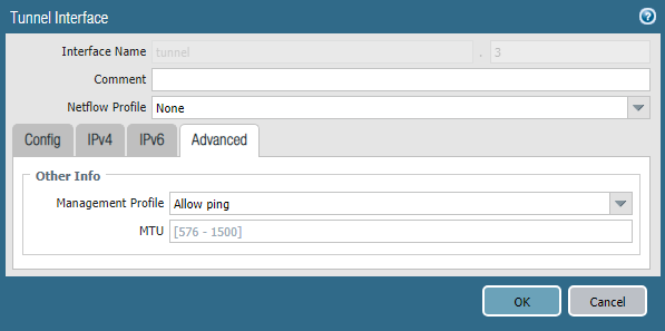
In the Advanced section, you can specify a Management Profile that allows ping to this interface, this can be useful for testing.
• Configure IKE Profile
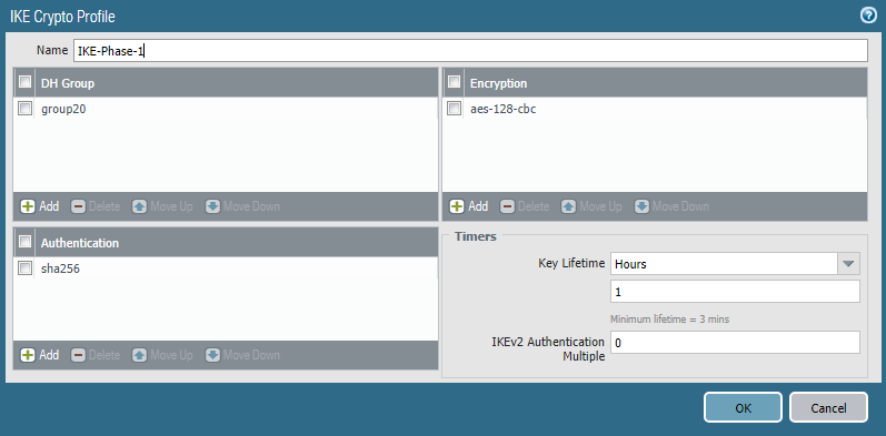
IKE Profileresponsible for the first stage of creating a VPN connection, here are the parameters of the IKE Phase 1 tunnel . The profile is created in the Network -> Network Profiles -> IKE Crypto section. You must specify the encryption algorithm, hashing, Diffie-Hellman group and key life. In general, the more complex the algorithms, the worse the performance; they need to be selected based on specific security requirements. However, it is strongly discouraged to use the Diffie-Hellman group below 14 to protect important information. This is due to the vulnerability of the protocol, which can only be leveled by using a module size of 2048 bits or higher, or elliptic cryptography algorithms, which are used in groups 19, 20, 21, 24. These algorithms are more productive than traditional cryptography. More details here . And here .
• Configure IPSec Profile
The second step in creating a VPN connection is the IPSec tunnel. SA parameters for it are configured in Network -> Network Profiles -> IPSec Crypto Profile . Here you need to specify the IPSec protocol - AH or ESP , as well as SA parameters - hashing, encryption algorithms, Diffie-Hellman groups and key lifetime. The SA settings in IKE Crypto Profile and IPSec Crypto Profile may not match.

• Configuring IKE Gateway
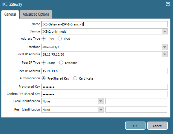
IKE Gateway is an object that identifies the router or firewall with which the VPN tunnel is configured. For each tunnel you need to create your own IKE Gateway. In this case, two tunnels are created, one through each Internet provider. The corresponding outgoing interface and its ip-address, peer ip-address, and common key are indicated. You can use certificates as an alternative to a shared key.
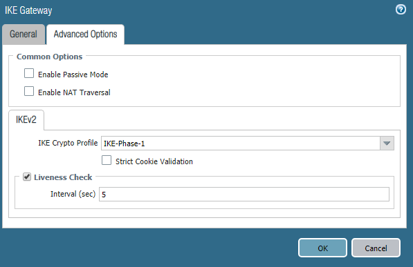
This indicates the previously created IKE Crypto Profile . The parameters for the second IKE Gateway object are similar, with the exception of IP addresses. If the Palo Alto Networks firewall is located behind a NAT router, then the NAT Traversal mechanism must be enabled .
• Configuring IPSec Tunnel
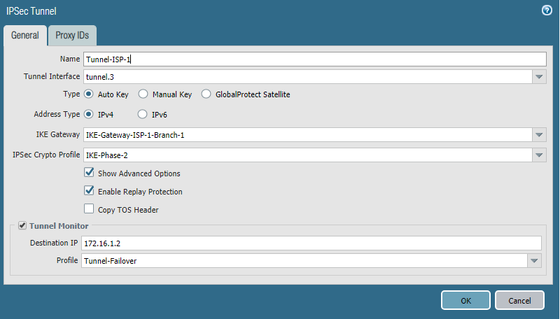
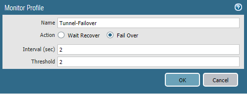
IPSec Tunnel is an object that specifies the IPSec tunnel parameters, as the name implies. Here you need to specify the tunnel interface and previously created IKE Gateway objects, IPSec Crypto Profile . To ensure automatic switching of routing to the standby tunnel, you must enable Tunnel Monitor . This is a mechanism that checks if a peer is alive using ICMP traffic. As the destination address, you must specify the IP address of the tunnel interface of the peer with which the tunnel is being built. The profile indicates the timers and the action in case of loss of connection. Wait Recover - wait until the connection is restored, Fail Over - send traffic on another route, if any. The configuration of the second tunnel is completely the same; the second tunnel interface and IKE Gateway are indicated.
• Routing setup
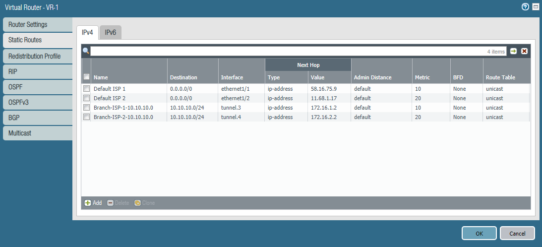
This example uses static routing. On the PA-1 firewall, in addition to two default routes, you need to specify two routes to the subnet 10.10.10.0/24 in the branch. One route uses Tunnel-1, the other Tunnel-2. The route through Tunnel-1 is basic because it has a lower metric. The Path Monitoring mechanism for these routes is not used. Tunnel Monitor is responsible for switching .
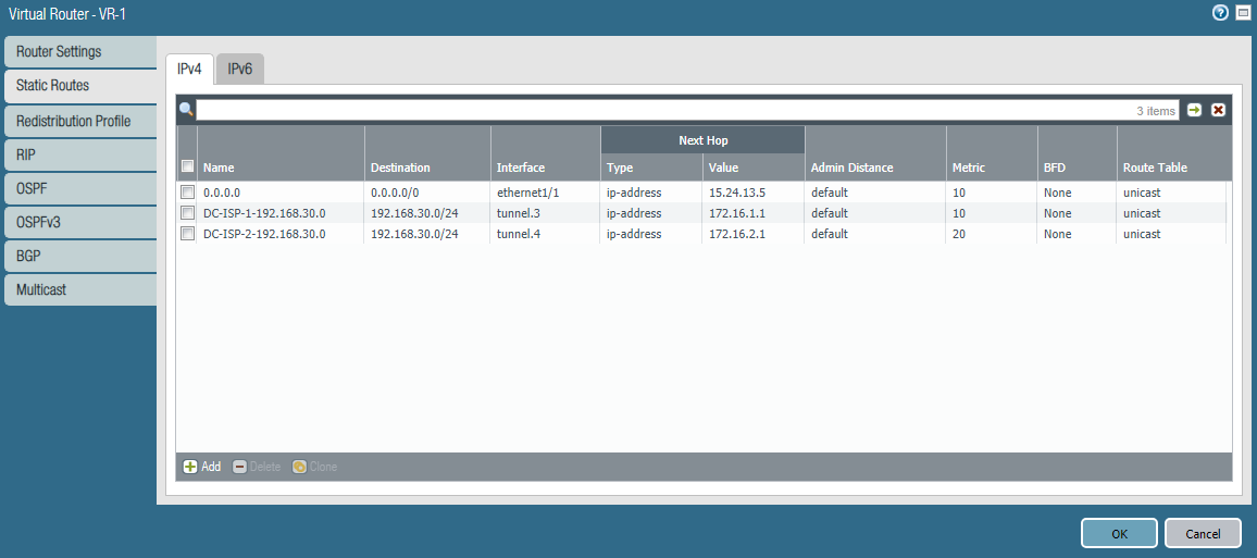
The same routes for the 192.168.30.0/24 subnet must be configured on PA-2.
• Configuring network rules
For the tunnel to work, you need three rules:
- For Path Monitor to work, enable ICMP on external interfaces.
- For IPSec, enable ike and ipsec applications on external interfaces.
- Allow traffic between internal subnets and tunnel interfaces.

Conclusion
This article has covered the option of setting up a fail-safe Internet connection and Site-to-Site VPN . We hope the information was useful, and the reader got an idea of the technologies used in the Palo Alto Networks . If you have questions about customization and suggestions on the topics of future articles - write them in the comments, we will be happy to answer.
