Tesla transformer with printed coils, soldered three components - and you're done
- Transfer
- Tutorial

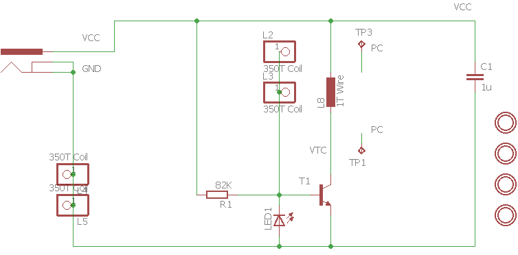
The use of printed coils reduces the complexity of manufacturing electronic devices. If they are made for sale, such as, for example, UKV-IP-2 blocks or RFIDs, this is a matter of cost, if it’s a convenience for yourself. So the proposed Tesla transformer does not have to be wound. The main thing is to wait until the board arrives, after which the assembly will take a couple of minutes. Required: a transistor (which is better - further), a 82 kΩ resistor and an LED.
... It all started with the fact that the author decided to assemble this design . But its complexity seemed excessive to him, and he decided to simplify it so that there was nowhere to simplify.
The device operates at a supply voltage of 10 to 35 V. The author suggests feeding it either through a boost converter from a sufficiently powerful PSU with a USB output, or directly from a laptop PSU. Of course, the second is more convenient.
Experimenting, the author developed four options for the board:
- almost idle, the author decided to sell the boards as souvenirs, for practical use they are useless
- working, 100 turns, without visible discharges in the air
- working better, 160 turns, there are still no visible discharges in the air (in fact, you can get small ones, read on)
- boards 150x150 mm, have not arrived yet, 240 turns, they will look like this:

The author ordered the boards at JLCPCB, they are quite complicated to manufacture, and LUT may not work.
Scheme: A
script for Eagle that calculates printed coils with a number of turns of more than 100. Or you can overcome the 100-turn limitation of an existing script in Eagle for the same purpose by editing it manually:
        dlgCell(4, 1) dlgLabel("Tur&ns"); // number of turns (Wound)
        dlgCell(4, 2) dlgRealEdit(n, 1.0, 350.0);
Version 2 board works:
The results of experiments with various transistors on the third version of the board:
The FZT851 transistor, when powered by 36 V, fails immediately. When the supply voltage is reduced to 12 V and without an LED in the bias circuit, it behaves as follows:
- no heating
- current consumption 0.017 A
- neonka is lit at a distance of 10-20 mm from the board
- no visible discharges in the air
- if you touch the board, the current through the transistor increases sharply, and it fails.
If you put a red LED in the bias circuit according to the scheme, the current consumption increases to 0.2 A, the neon glows at a distance of 30 mm from the board, at its terminals you can get small visible discharges in the air. But when you touch the board, the sharply increasing current consumption still disables the transistor.
With the BD243 transistor at 36 V, the results are the same as with the FZT851 at 12 V.
If you reduce the supply voltage to 5-6 V, you can still get a weak glow of neon.
The best results were obtained with the 2N3055 transistor. The author did not select it on purpose, he was just at hand. At 25 V and a red LED in the bias circuit (for some reason blue in the video), quite noticeable discharges in the air can be obtained at the neon terminals, but if you remove it, the transformer works without such discharges.