Bundles in steel. How are they formed
The topic of this article is somewhat unusual for Habr. I was prompted by her to write a simple and understandable desire to recall that at one time in our country there was a very high level of metal science, in particular its section on the study of the causes of the destruction of high-strength materials under load. Even before I got to LANIT, I was engaged in research on this topic and still have not lost interest in it. The problem of destruction of materials has also not become less relevant, therefore I bring to your attention a post on the causes of the appearance of delamination in high-strength steels.
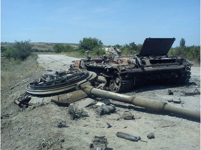
It was believed that the destruction of materials, in particular high-strength steels, occurs almost instantly at maximum load. However, numerous cases of destruction and the study of their causes have shown that catastrophic destruction can develop long before this maximum is reached.
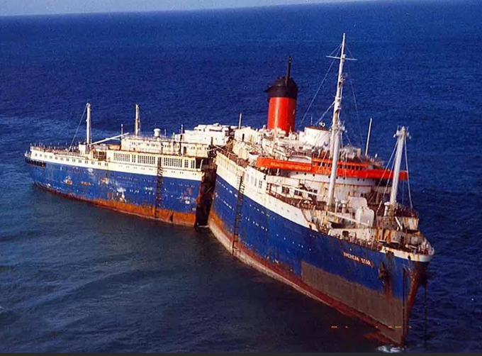
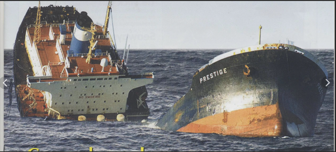
For the first time, massive cases of such destruction were recorded during the Second World War. In the United States, the Liberty series marine transports were serially produced to supply the Allied forces, the manufacture of which began to be widely used by welding of individual elements of ship's hulls (previously the hull sheets were connected by riveting). So these ships showed such a feature that literally after one or two sea crossings, extended cracks appeared on the hull, so their further operation caused serious concerns. There were even cases when the vessels were broken in half when they were excited. But since there were airtight compartments in the hulls, the halves remained afloat and continued swimming independently (by the will of the winds and waves).
 Source
As it turned out later, the cause of the cracks was the lack of attention to such details as cutting various technological holes in the hulls (manholes). Such openings should not contain sharp corners. Sharp angles, like stress concentrators in the hull, which occur alternately when the hull is at the top of the wave or on the crests of two waves, contribute to the gradual development of fatigue cracks. The welded body, unlike the riveted one, is a continuous medium in which the crack can propagate unhindered, which ultimately led to failure.
Nowadays, examples of spontaneous catastrophic destruction were noted on gas pipelines, when large diameter pipes (1220-1420 mm) made of high-strength steels made using controlled rolling technology were used for their construction. Gas in the pipeline is pumped under high pressure (75-100 atm).
In some emergency cases, crack propagation and pipeline rupture to a very large length were observed, which occurred at a tremendous speed, almost like an explosion. It is clear that such destruction entails catastrophic consequences. The cause of such damage was the microscopic cracks that occur in the steel pipe when its waterproofing is disturbed, the so-called stress corrosion under stress.
It may seem that a pressure of 100 atm does not pose a serious danger, since it corresponds to a load of only 10 MPa, and high-quality pipe steel has a yield strength above 400 MPa. But in addition to static stresses due to gas pressure, gas pipelines differ from other metal structures in their enormous energy capacity due to their long extent, they manifest the most pronounced large-scale effects of an energy nature due to the huge reserve of elastic energy concentrated in the pipe metal and compressed gas that is pumped through the pipeline. For example, in a pipeline with a diameter of 1420 mm at a pressure of 75 atm, the specific reserve of elastic energy in the pumped gas is 51 mJ per meter of the pipeline, and in the metal itself only 0.6 mJ / m. For comparison, in a pipeline with a diameter of 1220 mm, the supply of elastic energy of a gas at a pressure of 55 atm is half that of 26 mJ / m. Thus, a long-distance gas pipeline is like a single highly stressed system and behaves like a giant one-piece structure, subjected to a strength test.
With prolonged static loading and an increased supply of elastic energy in the loading system, many, even very plastic materials become prone to delayed fracture. This tendency is due to the gradual localization of plastic deformation near a microscopic crack and the subsequent development of fracture in the most stressed volumes of material. This circumstance makes the pipeline material extremely unpredictable with regard to the risk of sudden destruction. By the way, the fact that gas pipelines of increased diameter are more prone to catastrophic destruction was taken into account when laying the Nord Stream 2 and Turkish Stream gas pipelines - the diameter of the pipes in these pipelines is 1143 mm.
Both abroad and in our country, numerous studies have been carried out, a theoretical base has been developed, which has made it possible to establish the causes of the above-described damage and give recommendations on the prevention of such phenomena. In all cases, the originator of uncontrolled spontaneous fractures is crack nuclei, which can be very microscopic, develop for a fairly long time, and ultimately lead to almost instantaneous fracture, when the crack begins to propagate in steel with the speed of sound in it.
Below, as an example, I will give one of such studies, which shows how deeply it was required to delve into the mechanism of formation of uncontrolled destruction.
The case helped to choose a very interesting object for research - a long part made of medium alloy steel with a thickness of 80 mm. Several such parts, when quenched in water after heating for heat treatment, formed cracks - delamination in the middle of the thickness of the part. There was also a single case of complete separation of the part when quenching in thickness over the entire length, which was accompanied by a deafening crack, so that instead of one part, two half the thickness was removed from the quenching tank, which was not provided for by the technological process.
For the study, details were selected in which cracks extended to a length of 700 to 1,500 mm. It should be noted that the tensile strength of this steel after quenching and high tempering is at least 1300 MPa, and in the quenched state, the strength is even higher, therefore, the delamination of the parts, as well as the formation of such extended cracks in it, caused at least surprise.
In modern technological processes, cooling of workpieces in water after thermal or rolling heating is very widely used, which in principle leads to significant thermal stresses, but these stresses, as calculations show, are still below the yield strength of steel, so in this case it seemed that they could not lead to the destruction of the part.
 A source
Bundles in the blanks were detected after the final heat treatment. They were located in the lower edge of the workpiece along the length corresponding to the axial part of the sheet metal. Bundles extended to a depth of one to several centimeters, and in isolated cases they could lead to complete stratification of the workpiece by thickness.
Of the three parts in which delamination lengths of 780, 1000 and 1500 mm were found along the lower edge of the part, samples of 250-300x600 mm were taken, which were directly adjacent to the layer (axial zone of the sheet), as well as samples from the upper edge (hereinafter - edge of the sheet), which corresponded to the surface area of the ingot.
Templates were cut from samples using abrasive cutting, from which sample blanks were then cut using anodic-mechanical cutting to study macro- and microstructure, physical and mechanical properties (in the transverse and vertical directions relative to the rolling plane). Vertical samples for evaluating the toughness and stress intensity factor were cut so that the notch was located in the rolling plane in the central part of the sheet.
A detailed study of the mechanical properties of this steel (strength, toughness, ductility) on samples cut from areas adjacent to the crack and in defect-free zones did not reveal any deviations from the nominal values corresponding to this grade. Therefore, to identify the tendency of steel to delamination along the sheet thickness, a stress intensity criterion was used, denoted in the fracture mechanics as K 1c . This criterion has a rather strange, at first glance, dimension kg / mm 3/2 (MPa / m 1/2) The physical meaning of this criterion is the stress at which fracture occurs by separation, in the presence of a crack of a critical size in the material. The tests are carried out in such a way that a crack is grown in a special specimen by applying cyclic loads, and then gradually, applying an increasing tensile load to the specimen with a crack, the crack growth is observed, and at the moment of fracture, the stress value is fixed.
The sample for eccentric tensile testing is rather complicated in configuration (for which it received the slang name “pants”), and is no less difficult to manufacture (Fig. 1). According to GOST 25.506-85, it is referred to as type 3, we used samples with a thickness of 25 mm.
 Fig. 1. Sample for eccentric tensile testing A
fatigue crack was applied on a pulsator TsDM-10 with an upper load of 2000-3000 and a lower load of 500 kg. The pulsation frequency is 750 cycles per second, the number of pulsations is 3-5 thousand. The fatigue crack was nucleated at an upper load of 3000 kg, and its growth to a length of 1.5-2 mm was carried out at an upper load of 2000 kg. For more convenient observation of the growth of a crack, a printing ink diluted with kerosene was pre-instilled into the notch, which was absorbed into the crack during its growth. Tests of the samples were carried out on a DU-19 machine (France) with a record of the force – crack opening diagram. The fracture toughness was estimated using such a simple formula:
K 1c = [P / (t * b 1/2)] * [29.6 * (l / b) 1/2 - 185.5 * (l / b) 3/2 + 655.7 * (l / b) 5/2 - 1017 * (l / b) 7/2 + 638.9 * (l / b) 1/2 ], kg / mm 3 / 2
P - force to break the sample, kg;
t is the thickness of the sample, mm;
b is the width of the sample, mm;
l is the length of the notch with a fatigue crack, mm.
The stratification in the investigated parts is located in the center along the sheet thickness, spreads in different parts to different depths, its trajectory has a stepped character. No traces of plastic deformation are detected at the top of the bundle on transverse templates. The macrostructure of all the samples studied is characterized by a dense structure, there are no pronounced defects such as gas bubbles, segregation strips, areas with a rough dendritic structure.
No noticeable differences in the microstructure in different zones were noted.
The metal is characterized by a noticeable bandedness (Fig. 2), which is associated with the dendritic structure of the initial cast metal in the steel ingot and is characteristic of rolled alloy steels. Strips of various etchability are elongated along the rolling direction and noticeably differ in microhardness and in the content of alloying elements. The light bands contain an increased amount of molybdenum, nickel, copper, silicon, and manganese (determination was carried out using X-ray microanalysis), HB sulfides and line oxides are also concentrated in them, and the bundle also propagates through light bands.
The crack trajectory has a stepped character (Fig. 3), there are no areas indicating the occurrence of macroplastic deformation before fracture, numerous areas and grooves are observed on the surface, indicating a brittle nature of fracture.
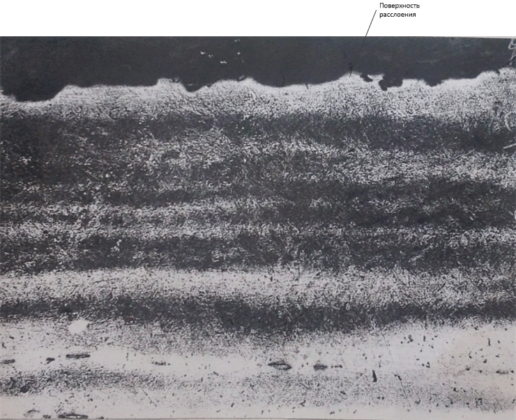 Fig. 2. The lamellar structure and the location of the HB. x 100
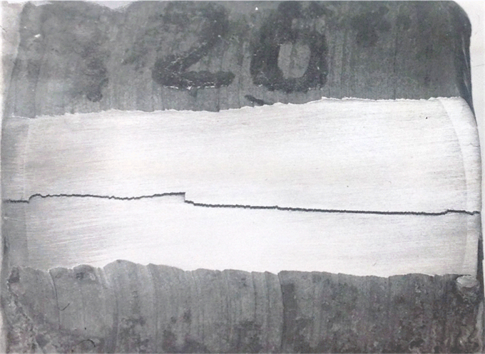 Fig. 3. The nature of the trajectory of the crack-delamination. x 1
Manganese sulfides, plastic, elongated along the rolling direction, were found in steel parts (Fig. 4), as well as complex oxides located along the rolling direction in the form of chains and lines (Fig. 6).
 Fig. 4. Location of sulfide inclusions. x400
Pollution of HB is typical for steel of the open-hearth method of smelting. In the central zone of the sheet, the thickness contamination with plastic sulfides and line oxides is slightly higher. Sulphides and oxides are selectively relative to the banded structure, in bands where there is an increased content of Ni, Mo, Cu, Si, Mn (Fig. 5).
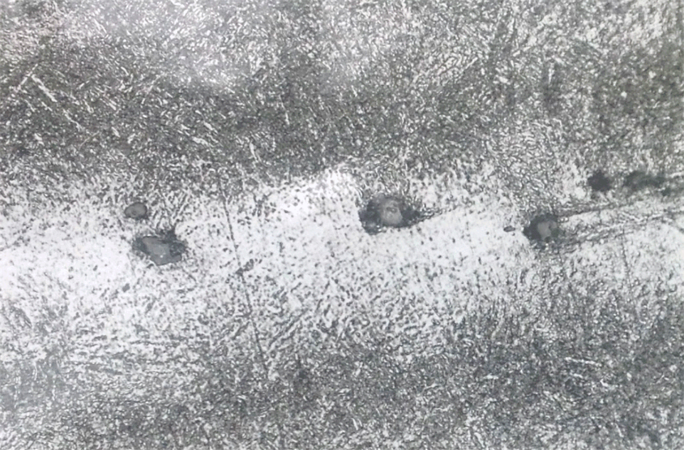 Fig. 5. The location of oxide inclusions in the banded structure. x400
In the viscous cup fracture of transverse and vertical impact specimens, numerous HBs, mainly sulfides, are observed; crack nuclei are not detected (Fig. 6, Fig. 7). The similar nature of the fracture indicates that the destruction passed through the accumulations of HB.
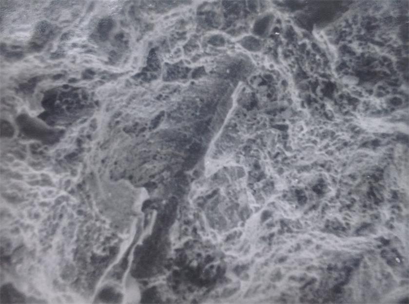 Fig. 7. The structure of the fracture of the transverse shock samples. x800
 Fig. 8. The structure of the fracture of vertical impact samples. x1600
We studied the effect of HB on the nature of plastic deformation and fracture by observing these inclusions at high magnifications.
On vertical specimens, brittle cracks are formed at the sites of sulfides and oxides occurring almost simultaneously on all inclusions in the field of view in the absence of plastic deformation of the base metal (Fig. 9).
The stress at which microcracks are formed on inclusions is 10-15% lower than the stress onset of plastic deformation of the base metal, determined by the appearance of slip marks. Microcracks that arose in sulfides initiate slip bands in the base metal, along which further increasing crack propagation occurs (Fig. 9-10).
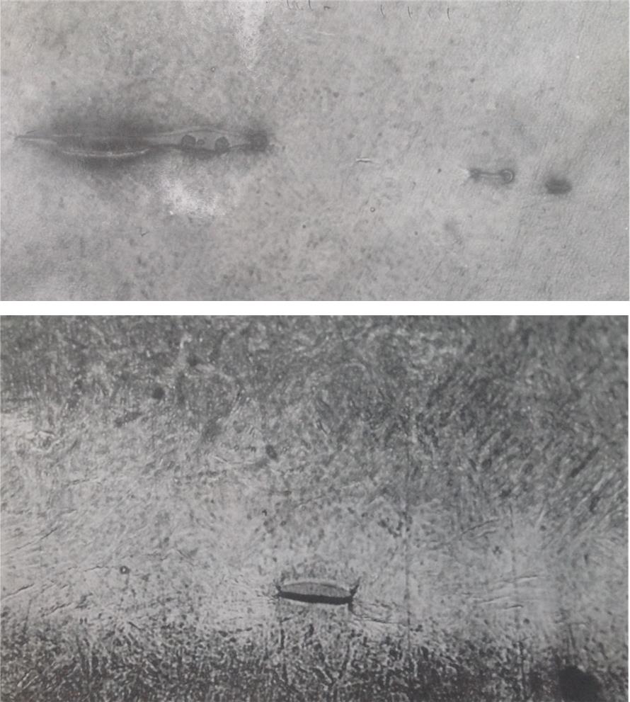 Fig. 9. The origin of cracks in sulfides (vertical samples, deformation = 1%). x500
On the lines of elongated sulfides, it is possible to facilitate the merging of several microcracks into one (Fig. 11).
In areas where no HBs are present, local plastic deformation with the formation of microcracks in slip bands is observed only when the metal has exhausted its plasticity margin.
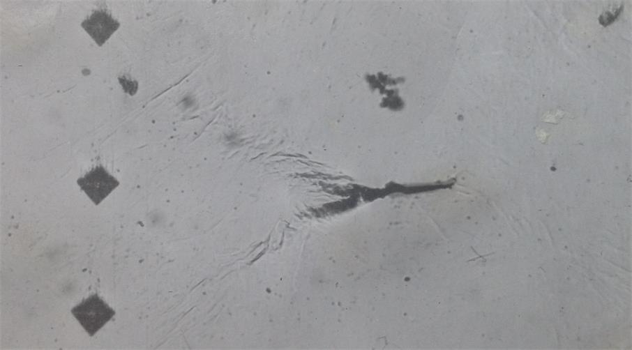 Fig. 10. Slip bands initiated by a sulfide crack. x 500
 Fig. 11. The development of cracks in the line of sulfides. x 500
The mechanical and plastic properties of steel in the longitudinal and transverse directions in the studied zones of the three investigated parts coincide with a probability of 0.95.
Steel is characterized by a significant dispersion of properties when comparing them on transverse and vertical samples relative to the rolling plane (as they say, the properties have a significant anisotropy coefficient). The plastic properties in the axial part of the sheet are noticeably lower than on the edge. When testing vertical samples for strength, ductility and toughness, these properties reflect to some extent the tendency of steel to form delamination, however, the calculated correlation coefficient between the delamination length in parts and properties in the vertical direction is significantly lower than the tabular coefficient at a significance level of 0.8, that is, this dependence is not significant.
The results of determination of K 1c by the method of eccentric tension of transverse samples 25 mm thick with a side notch and a fatigue crack (Fig. 12) passed the test of correctness by criteria of the ratio of the stress intensity factor to the yield strength of steel. With a selected sample thickness of 25 mm and a notch length with a crack of 28-30 mm, the transverse samples also do not satisfy this criterion (larger samples are required) and the results of their tests can only be used as approximate ones.
For vertical samples for eccentric tension, all necessary and sufficient test conditions are satisfied, and the results are correct when the thickness of the samples is 25 mm (Fig. 12).
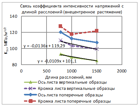 Fig. 12. Relationship between the stress intensity factor and the delamination length (transverse and vertical samples for eccentric tension)
The parameter K 1c significantly marks the difference in the quality of the metal of the axial zone and the sheet edge within the same melt. The intervals for K 1c in the axis and the edge of the sheet do not overlap even with a high confidence level of 0.95, the maximum value of K 1c in the axial zone is less than the minimum value of K 1c for the edge of the sheet. Such a clear difference in properties could not be obtained using the previously described indicators of ductility and toughness.
The correlation coefficient between the length of the stratifications on the parts and the values of K 1c for the axial zone is 0.89, which confirms the reliability of the relationship between these values.
Even more convincing is the combined parameter, which has a dimension of length and is directly proportional to the length of the embryonic crack, capable of spontaneous, spontaneous propagation at a level of tensile stresses below the yield strength (Fig. 13). The correlation coefficient between the length of the bundles and the parameter (K 1c / σ о2 ) 2equal to 0.94. This allows us to represent this dependence as a linear function. The extrapolation of this function with the length of the bundle equal to zero gives a critical value at which, with a larger value of it, the probability of bundle is also equal to zero. With an average yield stress of 1120 MPa for the axial zone, the value of K 1c , at which the probability of the appearance of delamination is close to zero, corresponds to 101 MPa / m 1/2 .
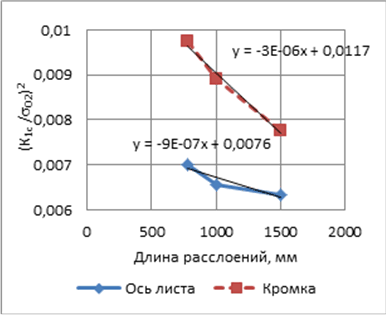 Fig. 13. Relation of the generalized indicator to the length of delamination (eccentric tension, vertical samples)
The cause of delamination in sheet steel is the mechanical fibrous nature of the metal due to the rolling of the dendritic inhomogeneity of the metal and the associated layered arrangement of non-metallic inclusions. The role of nonmetallic inclusions and other foreign particles is reduced to the stress concentration near the inclusions, the possibility of cracking of such particles, the breaking of the connection between the inclusions and the steel base, and the further propagation of the microcrack formed, which occurs at stresses lower than the yield stress. Subsequently, the crack propagates along the easiest paths in clusters of non-metallic inclusions and the particle-base steel interface.
The values of the found criterion of stress intensity show that at a stress level of 700-800 MPa (despite the yield strength of steel not less than 1050 MPa), the steel retains the ability to resist crack propagation if the size of the crack nucleus does not exceed 1.3 mm in depth, along the length 13 mm, when these indicators are exceeded, steel is destroyed. At the same level of stresses arising in the direction transverse to the rolling, the studied steel is able to resist brittle fracture if the size of the notch does not exceed 2.5 mm in depth and 25 mm in length.
The above example of the study of crack resistance clearly shows that steel failure in the presence of microscopic discontinuities and nonmetallic inclusions can occur at stresses below its yield strength, which, when calculating the strength of structures without taking into account this circumstance, can create the illusion of material reliability under operating conditions.

It was believed that the destruction of materials, in particular high-strength steels, occurs almost instantly at maximum load. However, numerous cases of destruction and the study of their causes have shown that catastrophic destruction can develop long before this maximum is reached.
For the first time, massive cases of such destruction were recorded during the Second World War. In the United States, the Liberty series marine transports were serially produced to supply the Allied forces, the manufacture of which began to be widely used by welding of individual elements of ship's hulls (previously the hull sheets were connected by riveting). So these ships showed such a feature that literally after one or two sea crossings, extended cracks appeared on the hull, so their further operation caused serious concerns. There were even cases when the vessels were broken in half when they were excited. But since there were airtight compartments in the hulls, the halves remained afloat and continued swimming independently (by the will of the winds and waves).

As it turned out later, the cause of the cracks was the lack of attention to such details as cutting various technological holes in the hulls (manholes). Such openings should not contain sharp corners. Sharp angles, like stress concentrators in the hull, which occur alternately when the hull is at the top of the wave or on the crests of two waves, contribute to the gradual development of fatigue cracks. The welded body, unlike the riveted one, is a continuous medium in which the crack can propagate unhindered, which ultimately led to failure.
Nowadays, examples of spontaneous catastrophic destruction were noted on gas pipelines, when large diameter pipes (1220-1420 mm) made of high-strength steels made using controlled rolling technology were used for their construction. Gas in the pipeline is pumped under high pressure (75-100 atm).
In some emergency cases, crack propagation and pipeline rupture to a very large length were observed, which occurred at a tremendous speed, almost like an explosion. It is clear that such destruction entails catastrophic consequences. The cause of such damage was the microscopic cracks that occur in the steel pipe when its waterproofing is disturbed, the so-called stress corrosion under stress.
It may seem that a pressure of 100 atm does not pose a serious danger, since it corresponds to a load of only 10 MPa, and high-quality pipe steel has a yield strength above 400 MPa. But in addition to static stresses due to gas pressure, gas pipelines differ from other metal structures in their enormous energy capacity due to their long extent, they manifest the most pronounced large-scale effects of an energy nature due to the huge reserve of elastic energy concentrated in the pipe metal and compressed gas that is pumped through the pipeline. For example, in a pipeline with a diameter of 1420 mm at a pressure of 75 atm, the specific reserve of elastic energy in the pumped gas is 51 mJ per meter of the pipeline, and in the metal itself only 0.6 mJ / m. For comparison, in a pipeline with a diameter of 1220 mm, the supply of elastic energy of a gas at a pressure of 55 atm is half that of 26 mJ / m. Thus, a long-distance gas pipeline is like a single highly stressed system and behaves like a giant one-piece structure, subjected to a strength test.
With prolonged static loading and an increased supply of elastic energy in the loading system, many, even very plastic materials become prone to delayed fracture. This tendency is due to the gradual localization of plastic deformation near a microscopic crack and the subsequent development of fracture in the most stressed volumes of material. This circumstance makes the pipeline material extremely unpredictable with regard to the risk of sudden destruction. By the way, the fact that gas pipelines of increased diameter are more prone to catastrophic destruction was taken into account when laying the Nord Stream 2 and Turkish Stream gas pipelines - the diameter of the pipes in these pipelines is 1143 mm.
Both abroad and in our country, numerous studies have been carried out, a theoretical base has been developed, which has made it possible to establish the causes of the above-described damage and give recommendations on the prevention of such phenomena. In all cases, the originator of uncontrolled spontaneous fractures is crack nuclei, which can be very microscopic, develop for a fairly long time, and ultimately lead to almost instantaneous fracture, when the crack begins to propagate in steel with the speed of sound in it.
Below, as an example, I will give one of such studies, which shows how deeply it was required to delve into the mechanism of formation of uncontrolled destruction.
The case helped to choose a very interesting object for research - a long part made of medium alloy steel with a thickness of 80 mm. Several such parts, when quenched in water after heating for heat treatment, formed cracks - delamination in the middle of the thickness of the part. There was also a single case of complete separation of the part when quenching in thickness over the entire length, which was accompanied by a deafening crack, so that instead of one part, two half the thickness was removed from the quenching tank, which was not provided for by the technological process.
For the study, details were selected in which cracks extended to a length of 700 to 1,500 mm. It should be noted that the tensile strength of this steel after quenching and high tempering is at least 1300 MPa, and in the quenched state, the strength is even higher, therefore, the delamination of the parts, as well as the formation of such extended cracks in it, caused at least surprise.
In modern technological processes, cooling of workpieces in water after thermal or rolling heating is very widely used, which in principle leads to significant thermal stresses, but these stresses, as calculations show, are still below the yield strength of steel, so in this case it seemed that they could not lead to the destruction of the part.

Material and research methodology
Bundles in the blanks were detected after the final heat treatment. They were located in the lower edge of the workpiece along the length corresponding to the axial part of the sheet metal. Bundles extended to a depth of one to several centimeters, and in isolated cases they could lead to complete stratification of the workpiece by thickness.
Of the three parts in which delamination lengths of 780, 1000 and 1500 mm were found along the lower edge of the part, samples of 250-300x600 mm were taken, which were directly adjacent to the layer (axial zone of the sheet), as well as samples from the upper edge (hereinafter - edge of the sheet), which corresponded to the surface area of the ingot.
Templates were cut from samples using abrasive cutting, from which sample blanks were then cut using anodic-mechanical cutting to study macro- and microstructure, physical and mechanical properties (in the transverse and vertical directions relative to the rolling plane). Vertical samples for evaluating the toughness and stress intensity factor were cut so that the notch was located in the rolling plane in the central part of the sheet.
A detailed study of the mechanical properties of this steel (strength, toughness, ductility) on samples cut from areas adjacent to the crack and in defect-free zones did not reveal any deviations from the nominal values corresponding to this grade. Therefore, to identify the tendency of steel to delamination along the sheet thickness, a stress intensity criterion was used, denoted in the fracture mechanics as K 1c . This criterion has a rather strange, at first glance, dimension kg / mm 3/2 (MPa / m 1/2) The physical meaning of this criterion is the stress at which fracture occurs by separation, in the presence of a crack of a critical size in the material. The tests are carried out in such a way that a crack is grown in a special specimen by applying cyclic loads, and then gradually, applying an increasing tensile load to the specimen with a crack, the crack growth is observed, and at the moment of fracture, the stress value is fixed.
The sample for eccentric tensile testing is rather complicated in configuration (for which it received the slang name “pants”), and is no less difficult to manufacture (Fig. 1). According to GOST 25.506-85, it is referred to as type 3, we used samples with a thickness of 25 mm.

fatigue crack was applied on a pulsator TsDM-10 with an upper load of 2000-3000 and a lower load of 500 kg. The pulsation frequency is 750 cycles per second, the number of pulsations is 3-5 thousand. The fatigue crack was nucleated at an upper load of 3000 kg, and its growth to a length of 1.5-2 mm was carried out at an upper load of 2000 kg. For more convenient observation of the growth of a crack, a printing ink diluted with kerosene was pre-instilled into the notch, which was absorbed into the crack during its growth. Tests of the samples were carried out on a DU-19 machine (France) with a record of the force – crack opening diagram. The fracture toughness was estimated using such a simple formula:
K 1c = [P / (t * b 1/2)] * [29.6 * (l / b) 1/2 - 185.5 * (l / b) 3/2 + 655.7 * (l / b) 5/2 - 1017 * (l / b) 7/2 + 638.9 * (l / b) 1/2 ], kg / mm 3 / 2
P - force to break the sample, kg;
t is the thickness of the sample, mm;
b is the width of the sample, mm;
l is the length of the notch with a fatigue crack, mm.
Macro and microstructure of steel
The stratification in the investigated parts is located in the center along the sheet thickness, spreads in different parts to different depths, its trajectory has a stepped character. No traces of plastic deformation are detected at the top of the bundle on transverse templates. The macrostructure of all the samples studied is characterized by a dense structure, there are no pronounced defects such as gas bubbles, segregation strips, areas with a rough dendritic structure.
No noticeable differences in the microstructure in different zones were noted.
The metal is characterized by a noticeable bandedness (Fig. 2), which is associated with the dendritic structure of the initial cast metal in the steel ingot and is characteristic of rolled alloy steels. Strips of various etchability are elongated along the rolling direction and noticeably differ in microhardness and in the content of alloying elements. The light bands contain an increased amount of molybdenum, nickel, copper, silicon, and manganese (determination was carried out using X-ray microanalysis), HB sulfides and line oxides are also concentrated in them, and the bundle also propagates through light bands.
The crack trajectory has a stepped character (Fig. 3), there are no areas indicating the occurrence of macroplastic deformation before fracture, numerous areas and grooves are observed on the surface, indicating a brittle nature of fracture.


Contamination with non-metallic inclusions and the influence of HB on the features of steel failure under load
Manganese sulfides, plastic, elongated along the rolling direction, were found in steel parts (Fig. 4), as well as complex oxides located along the rolling direction in the form of chains and lines (Fig. 6).

Pollution of HB is typical for steel of the open-hearth method of smelting. In the central zone of the sheet, the thickness contamination with plastic sulfides and line oxides is slightly higher. Sulphides and oxides are selectively relative to the banded structure, in bands where there is an increased content of Ni, Mo, Cu, Si, Mn (Fig. 5).

In the viscous cup fracture of transverse and vertical impact specimens, numerous HBs, mainly sulfides, are observed; crack nuclei are not detected (Fig. 6, Fig. 7). The similar nature of the fracture indicates that the destruction passed through the accumulations of HB.


We studied the effect of HB on the nature of plastic deformation and fracture by observing these inclusions at high magnifications.
On vertical specimens, brittle cracks are formed at the sites of sulfides and oxides occurring almost simultaneously on all inclusions in the field of view in the absence of plastic deformation of the base metal (Fig. 9).
The stress at which microcracks are formed on inclusions is 10-15% lower than the stress onset of plastic deformation of the base metal, determined by the appearance of slip marks. Microcracks that arose in sulfides initiate slip bands in the base metal, along which further increasing crack propagation occurs (Fig. 9-10).

On the lines of elongated sulfides, it is possible to facilitate the merging of several microcracks into one (Fig. 11).
In areas where no HBs are present, local plastic deformation with the formation of microcracks in slip bands is observed only when the metal has exhausted its plasticity margin.


Mechanical properties
The mechanical and plastic properties of steel in the longitudinal and transverse directions in the studied zones of the three investigated parts coincide with a probability of 0.95.
Steel is characterized by a significant dispersion of properties when comparing them on transverse and vertical samples relative to the rolling plane (as they say, the properties have a significant anisotropy coefficient). The plastic properties in the axial part of the sheet are noticeably lower than on the edge. When testing vertical samples for strength, ductility and toughness, these properties reflect to some extent the tendency of steel to form delamination, however, the calculated correlation coefficient between the delamination length in parts and properties in the vertical direction is significantly lower than the tabular coefficient at a significance level of 0.8, that is, this dependence is not significant.
The results of determination of K 1c by the method of eccentric tension of transverse samples 25 mm thick with a side notch and a fatigue crack (Fig. 12) passed the test of correctness by criteria of the ratio of the stress intensity factor to the yield strength of steel. With a selected sample thickness of 25 mm and a notch length with a crack of 28-30 mm, the transverse samples also do not satisfy this criterion (larger samples are required) and the results of their tests can only be used as approximate ones.
For vertical samples for eccentric tension, all necessary and sufficient test conditions are satisfied, and the results are correct when the thickness of the samples is 25 mm (Fig. 12).

The parameter K 1c significantly marks the difference in the quality of the metal of the axial zone and the sheet edge within the same melt. The intervals for K 1c in the axis and the edge of the sheet do not overlap even with a high confidence level of 0.95, the maximum value of K 1c in the axial zone is less than the minimum value of K 1c for the edge of the sheet. Such a clear difference in properties could not be obtained using the previously described indicators of ductility and toughness.
The correlation coefficient between the length of the stratifications on the parts and the values of K 1c for the axial zone is 0.89, which confirms the reliability of the relationship between these values.
Even more convincing is the combined parameter, which has a dimension of length and is directly proportional to the length of the embryonic crack, capable of spontaneous, spontaneous propagation at a level of tensile stresses below the yield strength (Fig. 13). The correlation coefficient between the length of the bundles and the parameter (K 1c / σ о2 ) 2equal to 0.94. This allows us to represent this dependence as a linear function. The extrapolation of this function with the length of the bundle equal to zero gives a critical value at which, with a larger value of it, the probability of bundle is also equal to zero. With an average yield stress of 1120 MPa for the axial zone, the value of K 1c , at which the probability of the appearance of delamination is close to zero, corresponds to 101 MPa / m 1/2 .

The cause of delamination in sheet steel is the mechanical fibrous nature of the metal due to the rolling of the dendritic inhomogeneity of the metal and the associated layered arrangement of non-metallic inclusions. The role of nonmetallic inclusions and other foreign particles is reduced to the stress concentration near the inclusions, the possibility of cracking of such particles, the breaking of the connection between the inclusions and the steel base, and the further propagation of the microcrack formed, which occurs at stresses lower than the yield stress. Subsequently, the crack propagates along the easiest paths in clusters of non-metallic inclusions and the particle-base steel interface.
The values of the found criterion of stress intensity show that at a stress level of 700-800 MPa (despite the yield strength of steel not less than 1050 MPa), the steel retains the ability to resist crack propagation if the size of the crack nucleus does not exceed 1.3 mm in depth, along the length 13 mm, when these indicators are exceeded, steel is destroyed. At the same level of stresses arising in the direction transverse to the rolling, the studied steel is able to resist brittle fracture if the size of the notch does not exceed 2.5 mm in depth and 25 mm in length.
The above example of the study of crack resistance clearly shows that steel failure in the presence of microscopic discontinuities and nonmetallic inclusions can occur at stresses below its yield strength, which, when calculating the strength of structures without taking into account this circumstance, can create the illusion of material reliability under operating conditions.
Do not forget that we have vacancies.
