Installing a Communication Cable Connector in a Super Game Boy
- Transfer
- Tutorial
The Super Game Boy cartridge, which allows you to play Game Boy games on SNES, is much like a regular Game Boy in hardware. They match the processor, the allocation of address space. But there is no connector for a communication cable, although the board has all the pads necessary to connect it. To add it, you will need the following components:
- Connector from a faulty Game Boy
- Three 220 ohm resistors
- Three 100 pF capacitors
- Three dual diodes (or six conventional germanium diodes)
So they look on the board of an ordinary Game Boy (there are positions 3 and 4 for some reason, 4 pieces

each ): Pinout of the connector and its counterpart for it:

It is not easy to open the cartridge case. There, not only a 3.2 mm hexagon is required, but also a hole for a screwdriver of too small a diameter. I had to drill a bit:

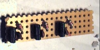
On a piece of the breadboard model, assemble this circuit three times:
So the result will look with the original dual diodes and other details from Game Boy:
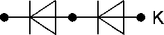
When determining the pinout of the original dual diodes, focus on the letter K or C (it is not clear whether the typo is in the picture or the letter really located next to the output of the anode, it is better to ring, otherwise the power will be shorted):
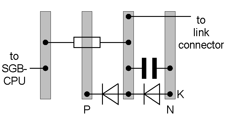
Connect the connector to the Super Game Boy board like this:
Вывод   | Место
разъёма | подключения
--------+-----------------------------------------------------------------
 1      | Напрямую к +5 В (вывод 1 слота для картриджа Game Boy)
 2      | Через цепь на самодельной плате на вывод 70 процессора
 3      | Через цепь на самодельной плате на вывод 69 процессора
 4      | Не подключать
 5      | Через цепь на самодельной плате к выводу 68 процессора
 6      | Напрямую к общему проводу (вывод 32 слота для картриджа Game Boy)
In all three circuits of a home-made circuit board, connect the pads marked with the letter P with the plus power, and those marked with the letter N with the common wire. The diodes will be closed by reverse voltage, and if static cable appears on the core, they will take it from the signal line to one of the power buses. Similar diodes are present in microcircuits, for example, 561 series.
This photo will help you find the required processor pins:

The following shows how you do not need to output the connector:

Install the modified Super Game Boy in SNES so far without a cartridge for the Game Boy, turn on the console, and it will display a message about the absence of a cartridge. Turn off the console. Install cartridges with the same multiplayer game in Super Game Boy and regular Game Boy. Connect the devices with a communication cable, turn it on and make sure that everything works.
The first time, although the author started everything, the color scheme switched in a strange way. He disassembled and reassembled the circuit, after which everything worked correctly. After that, he poured hot-melt adhesive over the hole through which the connector cable was removed, although it is better to also attach the connector itself.
Screenshot of a multiplayer game on Super Game Boy:
