Development and assembly of a photo lamp
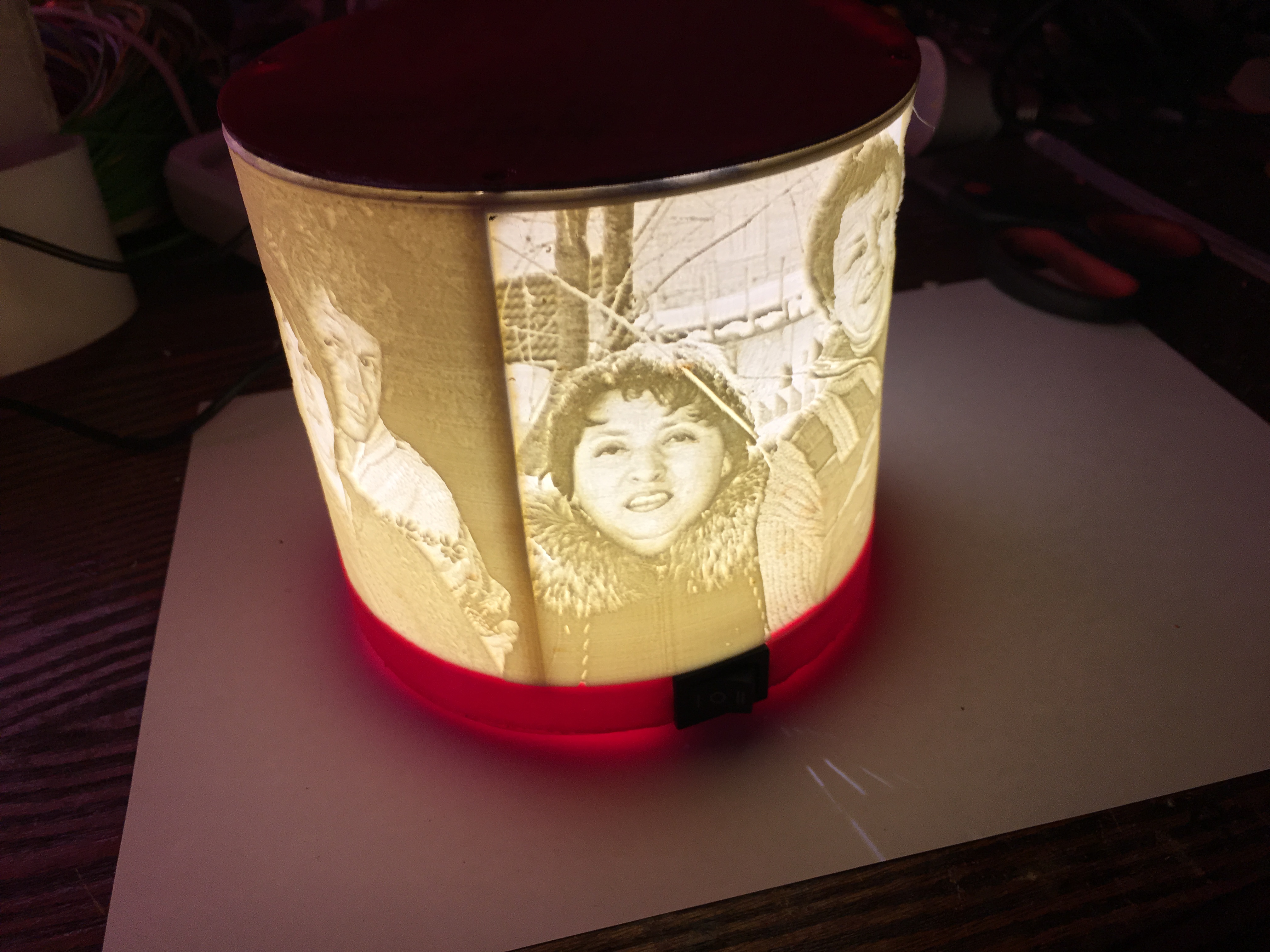
In preparation for the next family holiday - the anniversary of the parents, he decided to realize one wonderful idea - the creation of a unique photo lamp using 3D technology.
The idea did not come to me, I will be honest, I saw the implementation of my Internet friend - Nikolai Ralkov (for which I want to express my special thanks to him for the idea and help in solving the problems that arise).
So, let's go over in order.
The first thing you need to start with is the description of the design:
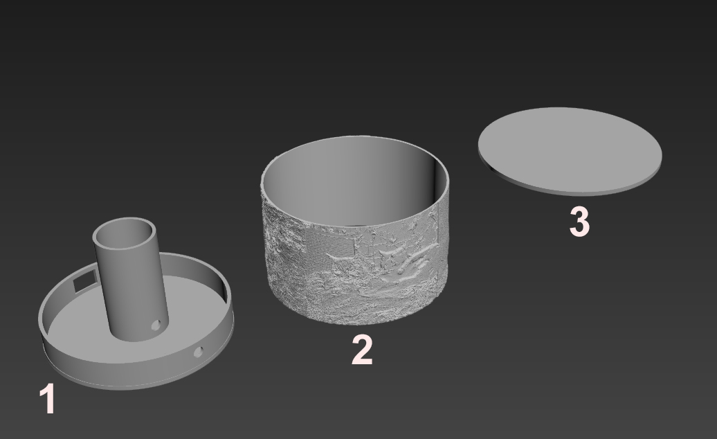
As you can see in the image, we need to design the basis of our design for its further printing on a 3D printer.
1. This is the base in which the power connector and the on and off button will be fixed. In my project, I slightly complicated the design by adding a key to 2 working positions, in which I - full light mode, 0 - off, II - half light mode (you can make any other - blinking, light-music, or even insert only 1 LED).
2. This is the body of the model through which light will pass. A mandatory requirement for it in the future is to make it from a matte material, for example, ABS plastic (PLA, PETG or SBS are not suitable for this task - verified).
We will prepare it from 4 images - photos that we will fit to one format in size and perform a little processing in a software package for working with raster images, for example, all our favorite Adobe Photoshop.
Prepared models are distilled and further prepared for work in a 3D editor. I will not describe this in detail, I will only indicate a link to a site where the bitmap image will be converted to embossed tile and saved in STL format.
A site for making tiles from raster images .
This is described in great detail in the following video:
3. This is the cover of our product. It is copied from the base or modified at your discretion. Ideally, prepare holes in it for fastening screws to the body of the product. This is necessary for further intervention in the design, in the event of a malfunction or repair.
After you have made a model, it must be sent to print - this is the longest process of our whole undertaking and it lasts about 1.5-2 days, depending on the accuracy of the print and model of your printer.
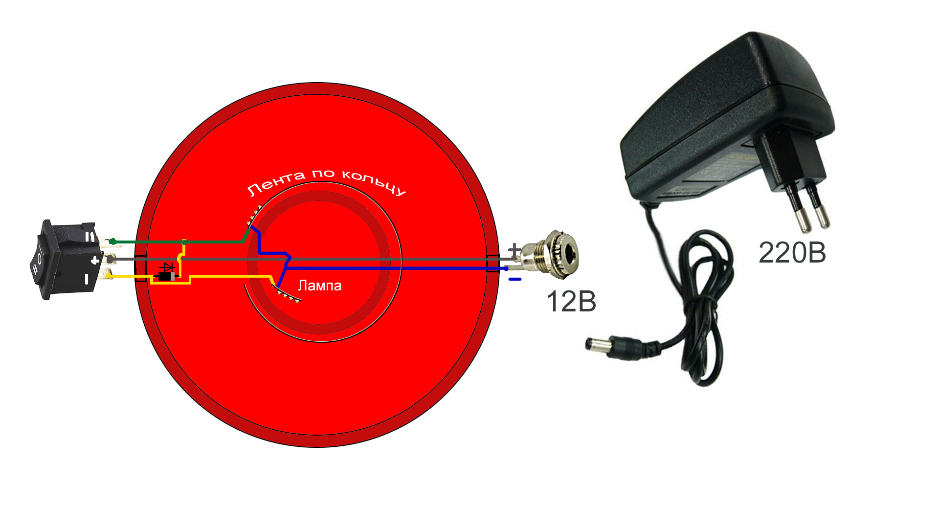
In the future, when the parts are ready, we will need to prepare the electrical components for our project. We will collect the following scheme:
We will need:
I detailed the assembly of the structure in the video. It is clear and detailed.
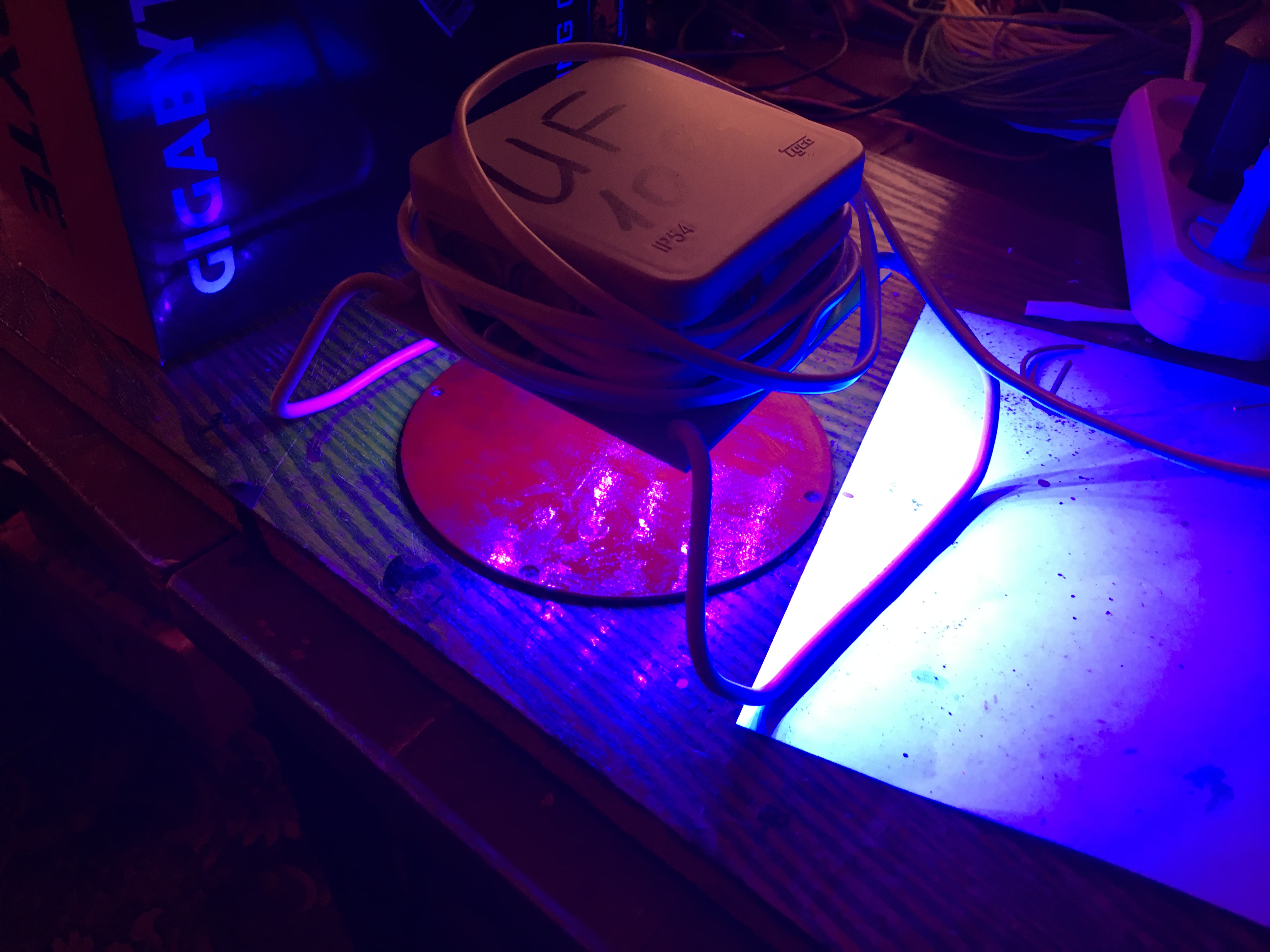
The only thing I want to add is that the lower and upper parts of the part can be processed and painted. It remains only to dry and assemble the product.
I sincerely hope that you liked the idea and it will be extremely useful to someone, as an opportunity to create a unique and memorable, and most importantly, a memorable gift to loved ones! Good to all!
The idea did not come to me, I will be honest, I saw the implementation of my Internet friend - Nikolai Ralkov (for which I want to express my special thanks to him for the idea and help in solving the problems that arise).
So, let's go over in order.
The first thing you need to start with is the description of the design:
As you can see in the image, we need to design the basis of our design for its further printing on a 3D printer.
1. This is the base in which the power connector and the on and off button will be fixed. In my project, I slightly complicated the design by adding a key to 2 working positions, in which I - full light mode, 0 - off, II - half light mode (you can make any other - blinking, light-music, or even insert only 1 LED).
2. This is the body of the model through which light will pass. A mandatory requirement for it in the future is to make it from a matte material, for example, ABS plastic (PLA, PETG or SBS are not suitable for this task - verified).
We will prepare it from 4 images - photos that we will fit to one format in size and perform a little processing in a software package for working with raster images, for example, all our favorite Adobe Photoshop.
Prepared models are distilled and further prepared for work in a 3D editor. I will not describe this in detail, I will only indicate a link to a site where the bitmap image will be converted to embossed tile and saved in STL format.
A site for making tiles from raster images .
This is described in great detail in the following video:
3. This is the cover of our product. It is copied from the base or modified at your discretion. Ideally, prepare holes in it for fastening screws to the body of the product. This is necessary for further intervention in the design, in the event of a malfunction or repair.
After you have made a model, it must be sent to print - this is the longest process of our whole undertaking and it lasts about 1.5-2 days, depending on the accuracy of the print and model of your printer.
In the future, when the parts are ready, we will need to prepare the electrical components for our project. We will collect the following scheme:
We will need:
- LED Strip Light. Length, power and quantity at your discretion. But it is important to remember that the power and length of the tape is selected commensurate with the power supply. In my case, the total length of the tape power of 9.6 W / meter does not exceed 1 meter for the power supply 12V 1A - 12W.
- Power Supply.
- On / off key
- Power connector under the connector of your PSU
- Wires and soldering kit + soldering equipment itself
- The project also used 1 diode
- A little patience and enthusiasm
I detailed the assembly of the structure in the video. It is clear and detailed.
The only thing I want to add is that the lower and upper parts of the part can be processed and painted. It remains only to dry and assemble the product.
I sincerely hope that you liked the idea and it will be extremely useful to someone, as an opportunity to create a unique and memorable, and most importantly, a memorable gift to loved ones! Good to all!