Underwater Ultrasonic Rangefinder Module. Part two
In the first part, we described the process of developing a test version of an underwater rangefinder module. The time has come to share information about the second version of the module, as we have implemented the proposed changes in the first article.
Change # 1: Temporary Automatic Gain Control (GAM).
In the process of testing the first version of the module, the problem of the roll-off of the reflected signal from obstacles located close to the emitter was clearly outlined. Some commentators on a previous post recommended VARU. Yes, the use of VARU was very appropriate. Now, in the first moments after sending a probe pulse, it is possible to minimize the gain and increase it over time.
The implementation of the VARU is shown in scheme No. 1.
The DAC of the microcontroller generates a voltage applied to the gate of the transistor Q4.
For the applied transistor, the characteristic of the introduced attenuation is experimentally obtained, depending on the voltage at the gate. Based on this characteristic, and the user specified environmental parameters, a table of values is calculated, which is sent via DMA to the DAC of the microcontroller.
In fact, the transistor, operating in linear mode, partially closes the useful signal from the output of the first stage of the amplifier to ground, thereby regulating the amplitude of the signal going to subsequent stages of the amplifier.

Change # 2: Boost converter to power the output stage.
Scheme number 2. Everything is simple here. The boost converter allows us to make our emitter a little “louder”. You can adjust the supply voltage of the output stage from 5 to 16 volts. Useful thing for long-distance measurements.
Change No. 3: MEMS gyroscope / accelerometer.
Scheme number 3. Built ICM20602 chip. This will make it possible to obtain not only information about the levels of reflection from objects on the ray path, but also the direction (angle) where the module is looking at this moment. Having made the simplest scan of the module (even twisting the module with your hand), you can get a realistic picture of the scanning object according to the principle of image formation by lidar.
The changes should also include the use of a cheaper, but not worse amplifier MCP669-E / ML. Gate drivers also selected the cheapest of the available TPS51604DSGR.
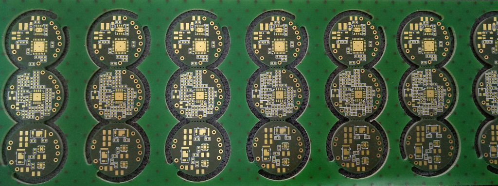
The shape of the printed circuit boards is made round, for a more rational placement inside the metal case.
For compactness and constancy of characteristics from copy to copy, the transformer is manufactured according to planar technology.
Iron is ready. What's next? The finest hour of programmers is coming!
Although the main low-level functionality has already been tested in work (driver management, working with ADCs, DACs, etc.), you still need to implement convenient interaction with the host, create and describe in detail the API that gives access to all the module's capabilities. Let me remind you that we chose UART as the physical interface for these purposes. And here it is worth mentioning that a disagreement appeared in the team on what type of protocol it is worth stopping for now: on text, or binary. On the one hand, the binary protocol is speed, ease of processing on the host side. On the other hand, the text protocol makes it easier to analyze the exchange of data (even in the Hyperterminal), and use meaningful commands / responses of the module. Here is a small example of interaction with the module using text commands in the Putty terminal:
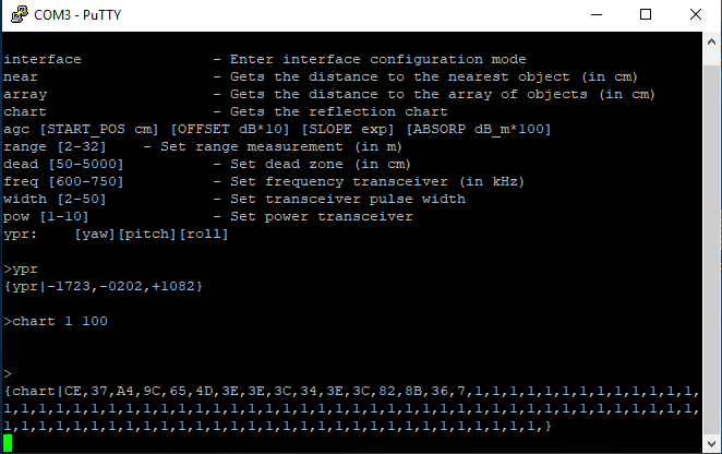
By pressing the TAB key, a list of all commands is displayed.
An example is given of using the YPR command, which returns the current value of the module direction along three axes (Euler angles).
The CHART command returns the value of the reflected signal from objects in the path of the probe pulse. You can set the resolution of the measurement (so far in centimeters) and the number of measurements.
Of course, the ideal case is support for both protocol options, both textual and binary. But we, unfortunately, are limited in time, and we would like to immediately direct our efforts towards a more acceptable option for users. Hence a modest request: mark in the voting option which would be more convenient for you.
For the next article, we will try to use the entire functionality of the module in order to be able to scan underwater objects and get a picture with the outlines of these objects.
PS
Opinions about the content for the second article within the team were divided: dry, a little, but now, either capaciously, beautifully, but then ... “Now” won.
I will dilute the dryness of the text with a few photos that were taken during the manufacturing process of the second version of the module.
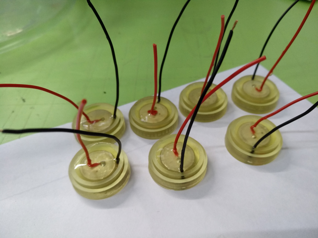
Assembly of emitters
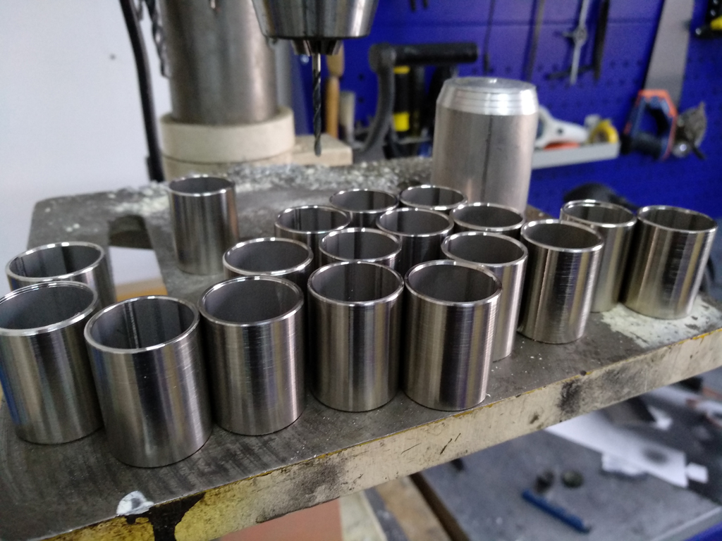
Machined metal housings
Laser-marked enclosures

Assembly of module boards
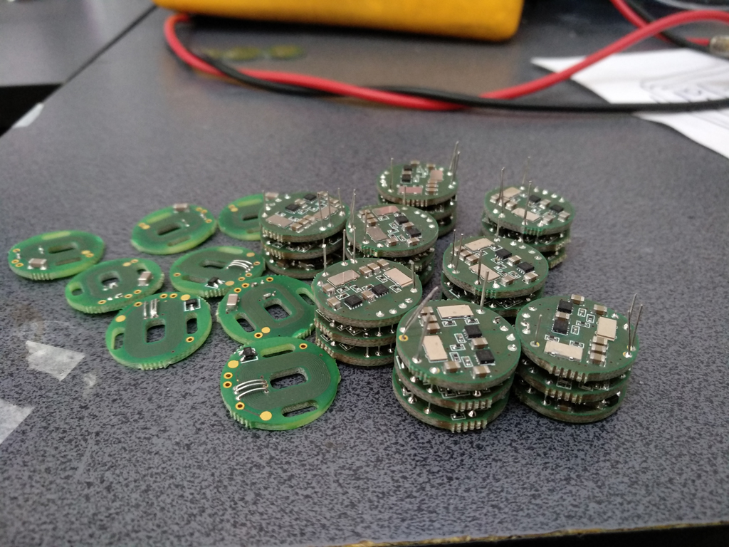
I will dilute the dryness of the text with a few photos that were taken during the manufacturing process of the second version of the module.
Assembly of emitters
Machined metal housings
Laser-marked enclosures
Assembly of module boards
Only registered users can participate in the survey. Please come in.