Turn off the lights and turn off the water

Such recommendations are intended to save and secure an apartment (house, etc.) from trivial troubles to serious damage, for yourself and others. Some people, because of the fear of leaving, turn off the electroautomatics in the panel and close the inlet taps of the water supply, the process itself is not very convenient to carry out manually, and therefore decided to make the budget system take on the automation of this process, and also added a little functionality. What came of it and how well - you can read under the cut.
First of all, I will say that in my case I will describe the system for use in an apartment, but in principle it is also quite suitable for a country house, and optionally in other rooms.
The first sketches of the solution look like this: at the exit from the apartment, install a button when pressed, which apartment electronics translates into one of the operation modes: safe mode (all consumers are turned off in the switchboard, water valves are closed) and normal operation mode (everything is on and valves are open). The question immediately arises: if you leave for a month, then everything is clear, everything is chopped off and left, and if you need to leave the apartment, work and other one-day departures safely for a long time, it turns out that it is better not to turn off the refrigerator (and other devices, which are also preferable not to turn off In particular, the equipment that will be turned on by the button). In the end, after thinking, I came to the conclusion that it would be right to do this: change the operation mode from safe to “on duty”, and call the usual operation mode “primary”.
The operation algorithm is as follows: the “main” mode is all on, the “on duty” mode is operated only by the necessary consumers (for short, the refrigerator). It is necessary to leave for a month or to be capitalized securely shut off the water, chop the central automatic. If daily care, press the button, the automatic will close the valve, and cut off the necessary machines, leaving the refrigerator on. Upon arrival, I pressed the button, the automation turned on everything and opened the water supply valve.
Based on the adopted algorithm, I decided to make a unit located in the panel that cuts the phases responsible for the equipment not included in the category refrigerator, and the unit is responsible for turning the water supply valves on and off.
Here I would like to retreat a little from the topic and tell why 2 blocks were chosen, and not one common one.
In connection with the experience gained in the development of devices, I came to the following: each unit must be responsible for a specific task, the simpler this task is, the simpler the unit is (naturally, not without kinking). The simpler the block, the less problems with it - due to the level of abstraction from other blocks. They are also made so that they can work separately from each other.
The blocks use standard modules that are easy to buy and replace. Again, with standardized management, you can put another, more reliable, improved or more functional unit. The control units are based and typed under the Arduino nano, I believe that this controller module with a margin is enough to control the unit.
Returning to the issue of power and wiring. To power the units using a constant 12 volts.
Here I would also like to clarify that I used my vision on this issue: there are already quite a lot of consumers from 12 volts and less starting from LED lighting strips and it is logical to use this voltage for low-voltage consumers in an apartment, besides, in general, this is a safer voltage .
Here and below, I indicate the nominal voltage of 12 volts, in fact, the output from the power supply will be approximately 13-14 volts, which would be a margin for voltage drops on the wires and consumers would reach 12 V with small tolerances. As a result, in my opinion, the generalized wiring scheme in an apartment should be this:
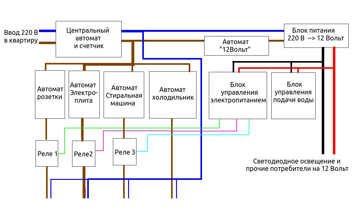
Naturally, there may be more automatic machines with sockets, and 12-volt power supply units with their automatic machines can also be more than one (there may be options for loading or backing up some systems - This can be a separate article to write).
Power control unit (bue)
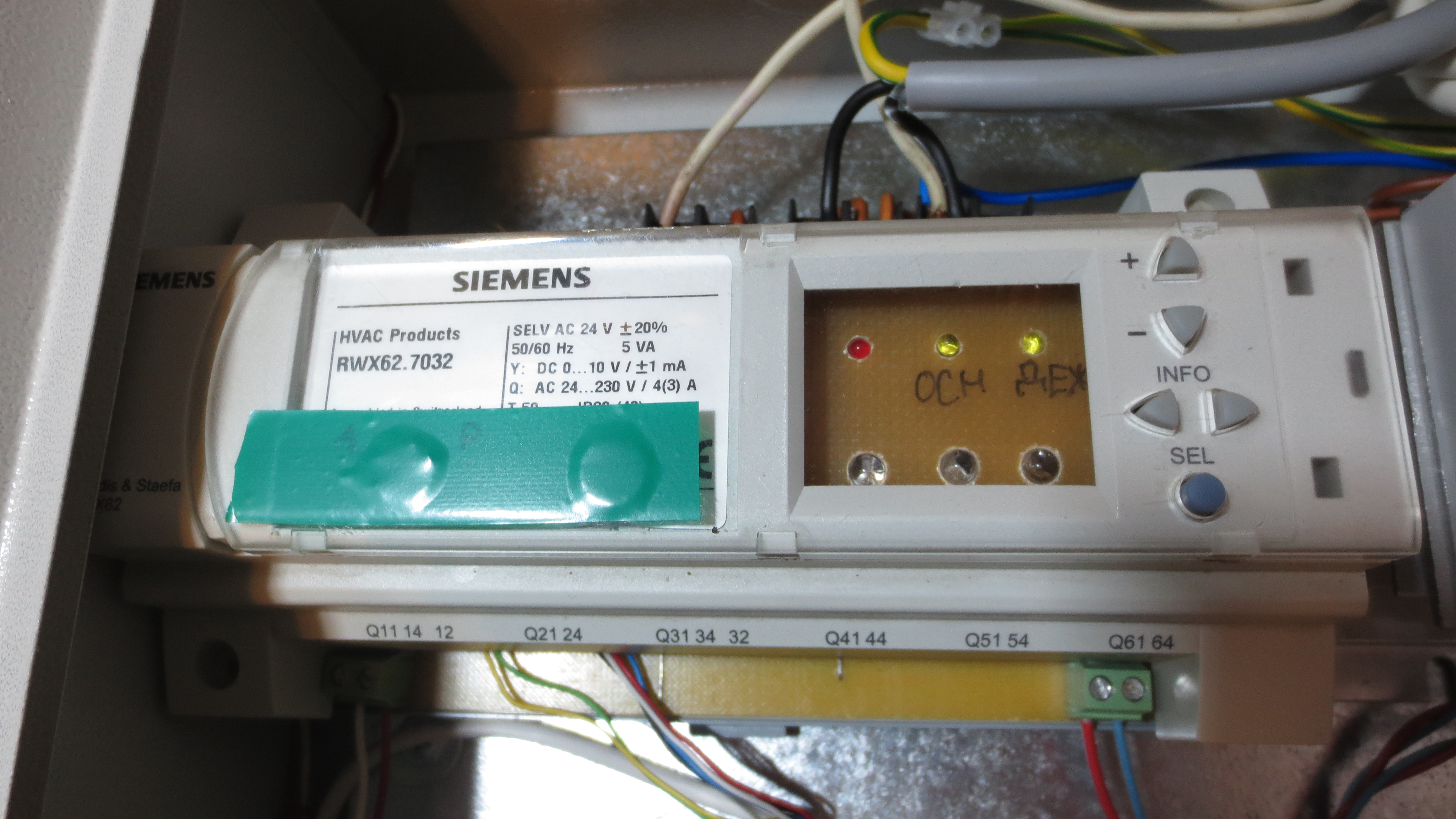

The unit controls 3 sources of electricity, 2 electromechanical relays are on the main board, and 1 solid-state relay is connected outside the unit case. The main board of the block is not universal and was designed specifically for this block. Electromechanical relays took the maximum to 16 amps.

I know many supporters related to the relay with great distrust - even here I have a lack of confidence in this figure. In the direction of protection of use, I would say that switching will not occur often and under full load it is not planned to work properly, in general I would divide the load by a smaller amperage, i.e. more machines with fewer amps each, but it all depends on the wiring divorced in the apartment. I will look at what will happen during the operation, then if necessary I will already accept some innovations. Implemented in the block the gradual inclusion of the load Each of the 3 relays is turned on with a certain period of time, which I think will generally have a positive effect on the electrical network in the apartment. On the button body there are indicators (LEDs) denoting the current mode of the unit and warning / alarm status. For indication of the mode one two-color LED is used. Green - the main, red - on duty. In the process of switching from one mode to another, the indicator flashes in that color to which mode the transition is made. On the top cover of the unit there is an indication of the presence of voltage after the relay (white LEDs), also the display indicates the operating modes - but decided not to turn it on. there is a button with indication of the current mode, and the block will stand in the shield, and there the indication of the modes is not particularly relevant. Also information about the presence of voltage receives the controller unit and analyzes this state, in case the relay is turned off but the voltage is still present (the relay is jammed), a warning indication will go - often a flashing LED (round) in the button body. Successfully under the unit came the "Siemens" case under the din rail, it seems from the controller for ventilation, but still had to modify it a bit.
Control unit for water supply valves (BUPV)
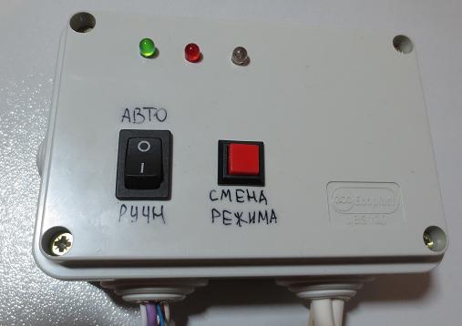
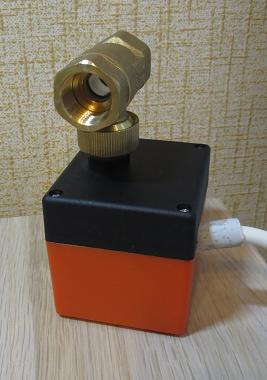
The unit controls 2 motorized ball valves (bought on Ali, price 1 pc. ~ 900 rubles). Both cold and hot water valves are the same. The ball valve is controlled by the 2-wire 220V + zero, fed to one wire 220 - it closes the valve, feeds to the other - it opens the valve. The control motor spins only in one direction, i.e. it is impossible to start opening completely without closing. Inside the valve body there is a microswitch and upon completion of the process of closing or opening it automatically removes the voltage from the motor.
The algorithm for this block:take control command, close the valve or open the valve. The module has 2 control modes automatic and manual. In automatic mode, commands are received coming only from the power management unit. In manual mode, commands are executed from a button on the lid of the water supply control unit, while commands from the power supply control unit are ignored. The block has open and closed modes. There are 3 LEDs on the block lid, 2 of which just indicate in which current mode the unit is located (green - valves are open, red - valves are closed), as well as in BUE the LED flashes in transition mode, which unit switches to, about 3 I will tell LED a little lower. This unit is installed in close proximity to the valves with access to the display and control.
Implementing the blocks, I came to the idea that there is a certain category of devices that perform their work for quite a long time and it is not advisable to disconnect them from the network “right now” - such devices include a washing machine, a dishwasher (most likely you can include some other devices, I will give an example of a washing machine that is relevant to me). Sometimes it can happen that the washing is started and if the power is turned off, the process will remain incomplete and spoiled, so I decided to implement an additional algorithm for working with the washing machine.
Algorithm of work with the washing machine:During the washing process, a signal is sent from the washing machine to the water supply control unit that a wash is in progress. The unit analyzes this signal if the washing is on and suddenly decided to transfer the unit to standby mode, the unit does not close the cold water supply valve (the hot water valve will be closed). If the signal goes "washing" (washing ended) in standby mode - the unit will close the cold water valve. The reverse process will not occur (i.e., if the unit is already in standby mode and the valve is closed, when the “wash” signal appears, the valve will not open).
I will return to the 3rd LED on the lid of the block - it shows the status of whether the wash is currently on.
The implementation of receiving the control signal from the washing machine.
Instead of the preface:in fact, I am surprised that household appliances (simple, not specialized) do not have the simplest electrical contacts (closed-open) talking about its current state - at least that is the process of work or it stands idle, it would be much simpler process automation, and then it would not be necessary to make a garden to electrically obtain such information. I believe that this would be an additional plus to the functionality of household appliances, with minimal costs from the manufacturer.
So you want to get a signal from the washing machine that is washing. Looking for any solutions on the forums on the forums and watching the process of starting and ending washing, also looking at the schemes I learned that more than half of simple washing machines from different manufacturers work on the standard type of boards and the algorithms of their work plus or minus the same. I came to the conclusion that the most suitable option is the lock of the lock of the hatch for loading the laundry. At the beginning of washing, the lock locks the laundry loading hatch, and at the end of washing it unlocks it. The scheme of such a lock is well-spread and the same on most washing machines.
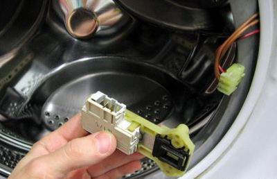

Lock operation:when 220 volts are applied to it (contacts 1 and 3) it locks the door, if the voltage is removed - it stops blocking it. My solution is to use a relay with 220V coil power supply connected in parallel with the hatch lock - this should not damage the washing machine, only the washing machine will consume slightly more current during washing (by the amount of current that the relay coil consumes). Since My washing machine is quite old and there is no guarantee for a long time, then this option was quite suitable for me. Probably still there are more interesting options for how to get information electrically that the washing machine washes, I would be glad to know about them.
The organization of communication between the blocks
I will give a general diagram of the electrical interaction between the blocks and their strapping

The connection between the blocks is carried out via the RS-485 hardware interface, with the SRDB2 software protocol, which I described earlier in my article . In my case, the BUE is the leader and sends one of the commands (open the valve, close the valve, issue your current status), the BUPV always responds with its current state.
Algorithm work in conjunction:When you press the control button of the BUE to switch to standby mode, the BUE sends a command to the “close valve” to the BUPV. The BUPV looks at the current state of washing, if there is no washing, it starts to close both water supply valves, responding to the BUE simultaneously that the valves are closing, if the washing goes, then only the hot water valve closes, also informing the BUE about this state. After closing the valve, the BUPV reports that a successful closing of the valve (s) has occurred. BUE seeing from the answers that the valve was successfully closed, and also if the washing is not going on, it removes the voltage supplying the washing machine and valves. If there is a wash, then the voltage from the washing machine is not removed. Constantly being polled current status BUPV. Only after obtaining the status “washing is completed” (this status of the BUPV issues after the washing is completed and the hot water valve is closed) the BUE removes the voltage supplying the washing machine and the valve. When switching to the “main mode”, the BUE sends the “open valve” command and sends the voltage to the relays, including them in turn, at intervals of time.
The control of the water supply valve is organized on the basis of a switching relay. It has a normally closed state for the “open valve” state. If you apply voltage to the washing machine (relay "washer") and do not energize the relay responsible for controlling the valve, the valve will open - this is necessary in case of transition from the "on duty" state to the "main" state. When switching from the “main” mode to the “on-duty” mode, without relieving the voltage from the washing machine, the valve control must be energized at the relay - thereby starting the process of closing the valve. At the same time, the valve will close or be in the closed state while control signals are applied to both relays (relay for supplying washing machine and relay for supplying valve control), and since after closing the valve the voltage from the “erasers” relay is removed, the state of the valve control relay no longer matters (some time after switching to standby mode, I remove the voltage from the valve control relay, thus preparing it to wait for the state to open valve). This ensures the minimum time load on the valve control relay.
Автономная работа блоков
In my experience of operating automation, I will say that it is impossible to take into account all the nuances in the development of automation, so I think it is right to enter the manual or autonomous control mode for the blocks - because This will facilitate some moments of interaction with her in unusual situations. On the lid of the BUPV there is an automatic and manual mode switch. Work with automatic interaction is described above. In manual mode, the BUPW ignores commands from the BUE. On the lid of the BUPV there is a button to open all valves to open and close all valves. In the case of manual control of the BUPV, the indications “washing” are ignored. This is done specifically for emergency shutdown of valves, i.e. if, when operating in the main mode, the washing machine is working and the pipe has burst, then for quick shutting off of water it is required to install the unit in manual control and by pressing the button to transfer it to the mode all valves are closed. When operating the BUPV in manual mode, the BUE does not analyze the data coming from the BUPV, but performs direct functions when it is transferred to the duty officer, it turns off everything. It is understood that in the manual mode, the person independently assumes the responsibility of how to control the device correctly and better, at the same time the overlapping of the false signal “washing” is “overlapping”.
Unscheduled emergency power outage
Both units record their state in non-volatile memory, in case there is a power outage in the apartment, while after it is supplied, the units will return to the state that was before the shutdown. An exception is the state when the wash was on, since when electricity is disconnected, most likely this process is corrupted, then the blocks closing the valve go into standby mode, while on the button for changing the BUE modes the LED on the incomplete washing process flashes. The indication of the incomplete washing process is removed by pressing the button for changing the BUE mode.
P.S.after the development and the start of operation, everything works as planned, but the idea has already emerged of how to make the blocks better, namely, to abandon the valves at 220 volts and switch to 12 volts - in order to remove 220 volts from the BUPV in general, increase the number of relays in the BUE and take them out of the hull - making them also quickly replaceable - (but that's another story. Interestingly, the people’s opinion about this development is generally (you’d put it at home) - I understand that I didn’t invent something new, I’m sure that the offices involved in smart homes with ease pr dlozhat like that, I just approached the issue from a budgetary side automate this process results in a program block codes do not see much point - function blocks themselves are simple:. accept / send data Serial, turn on / off the LEDs / relays, learn the state of the button - it is on every second site on Arduino. If someone has a desire to make exactly the same device, in contacts there is my e-mail, I can send program codes of blocks and explain in more detail how, what and why. The approximate price of the development came out at 4-5 thousand rubles, this is without evaluating the self-created boards and other "priceless things."
P.P.S. Link to the video of the device.
