Self-synchronous circuits. Calculation of logical functions directly on the graph of events. Part 3. Decomposition
I recall an important conclusion from the previous parts. For a cyclic sequential behavior that does not contain multiple signals (switching over a cycle more than two times), the minimum logical function of each signal can be represented in the following form (naturally, in the absence of CSC conflicts):
1)
where a * b * ... * c is the implicant of one or more variables. g + h + ... + i - this is possibly an empty set of implicants consisting of one variable. x * f is an implant of 2 variables, the presence of which in a minimal form is not necessary. All variables, except x, can be included in the formula both in direct and inverse form, depending on the arrangement of signs of the corresponding events. All variables are included in the formula as arguments strictly once.
Before moving on, we will take a closer look at a phenomenon such as decomposition. First of all, decomposition is of interest, which preserves self-synchronization. When decomposing a logical NOT-AND-OR function, a new element can be distinguished:
a) one or more implicants,
b) several signals (variables) of one implicant,
c) one input inverter.
To begin with, we consider a special case of the NOR AND function. The behavior of such a logical function (x = a + b + c + d) for the model under consideration:

Several signals can be distinguished from it as a separate element.
In fact, the selection of a new element during decomposition is the addition of a new signal (f). In order to maintain correct behavior, semi-modularity, and self-synchronization, switching of the newly added signal f must have consequence events. Since the decomposition affects only one element of the circuit (in this case, x) and does not affect the remaining elements of the circuit, switching the signal f can only cause switching the signal x. Otherwise, the logical function of another signal would depend on signal f. Given this conclusion, let us try to highlight any several variables except the variable a as a new element f. Take for example the variables b and c. They form the logical element f = b + c.
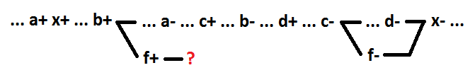
As can be seen, for the f + event it is impossible to determine the consequence event without violating the correctness of the behavior. Any group of signals that does not contain the variable a cannot be allocated as a separate element while maintaining self-synchronization.
A signal such as a in this example will be called switching on. In the general case, the switching signal for the function OR (AND) is a signal, switching it to 1 (0) changes the value of the function from 0 to 1 (from 1 to 0). To maintain self-synchronization during the decomposition of the logical function OR (AND) when selecting a new element, you must use the switching signal. When selecting a new element, it is also necessary to use only the signals forming a connected chain (in the example below a + b). x = f + c + d, f = a + b.
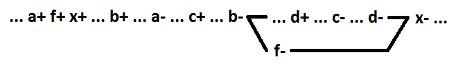
When using a + b + d signals, self-synchronization is not preserved.

Thus, for sequential behaviors without multiple signals during the decomposition of the logical function OR (I), highlighting as the new element the first few in the process of deployment of the signals, starting from the one that includes, ensures that the circuit is self-synchronized.
Now consider the non-OR function (x =! A +! B). As a separate element (f) while maintaining self-synchronism, we can select only the input inverter that corresponds to the switching signal (x = f +! B, f =! A). Separation of other input inverters as a separate element will lead to a violation of self-synchronization.
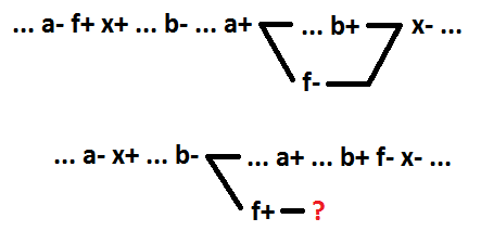
Let's move on to the AND-OR function. Similarly, as the switching signal for the OR function, we define the switching implicant for the AND-OR function. This is an implicant, changing the value of which from 0 to 1 leads to a change in the value of the function from 0 to 1. Similarly, as it was found out for the OR function, for sequential behaviors without multiple signals when decomposing the logical AND-OR function, selecting the first few as a new element in the process of deployment, the implicant, starting with the inclusion, guarantees the preservation of self-synchronization of the circuit. Otherwise, self-synchronization will be broken. In the example below, before decomposition x = a * b + c. After decomposition, x = f + c, f = a * b.
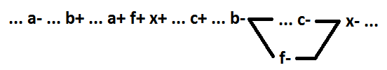
Now for the AND-OR function, we consider the selection as a new element of several variables included in the same implicant. Only minimal functions are considered. Below are all possible options for the example of the function x = a * b * c + d (for option 4 - x = a * b * c + d + e, for option 6 - x = a * b * c * d + e) . The highlighted element is f = a * b.

In option 1, switching one of the allocated signals (a +) is the cause of the x + event. In option 2, switching one of the allocated signals (a-) is the cause of the x- event. In options 3 and 4, the switching of one of the allocated signals (a + and a-, respectively) is located between the events x + and x-, and is not the cause of the event x-. Option 5 is a special case of option 4, when the implicant, in which the signals are allocated, is inclusive. The remaining option 6 - all switching of the allocated signals are located between the events x- and x +, and are not the causes of the event x +.
As you can see, in options 1 and 6, the f- event cannot be positioned correctly. Such transformations are not decomposition with preservation of self-synchronization. In options 2, 3 and 4, self-synchronization is maintained. But the value of the function x turns out to be different from f * c + d (f * c + d + e for 4 options). For 2 options - x = f * (d + c), for 3 options x = c * x + d *! F + x *! F, for 4 options x = (f + d) * (e + c). Such transformations are not decompositions.
Only option 5 is a decomposition with preservation of self-synchronization (x = f * c + d). In this case, as a separate element in the inclusion implicant, the first several signals are selected, starting from the inclusion (the signal including the implicant And is the same as the signal including the And function). But, as shown above, a similar result is achieved in two steps. First, the inclusion of the implant is highlighted. At the second step, the first few signals are selected in the new element, starting with the switching signal.
Let's move on to the NON-AND-OR function. Let us single out the input inverter as a separate element. Signal a corresponds to the input of element x, to which a dedicated input inverter is connected (f =! A).
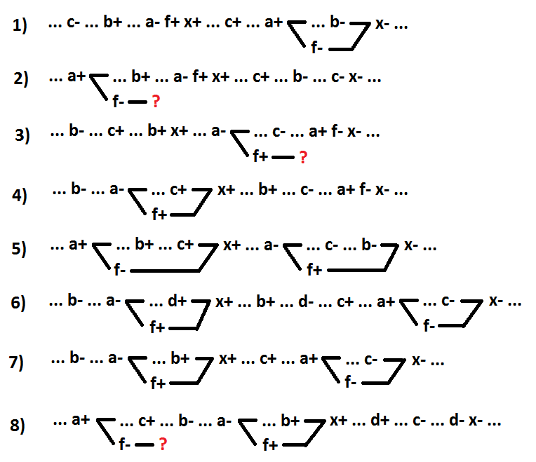
Options 1 and 2 - switching signal a is the cause of the event x + (1 - x =! A + b * c, 2 - x = b *! A + c). Options 3 and 4 - switching the signal a is the cause of the event x- (3 - x =! A + b * c, 4 - x =! A * b + c). Options 5 and 6 - switching of signal a is located between the events x + and x-, and is not the cause of the event x- (5 - x = b *! A + c, 6 - x =! A * b + d + c). Option 7 is a special case of option 6, when signal a is a switching signal including implicants (x =! A * b + c). The remaining option 8 - all signal switching a is located between the events x- and x +, and are not the causes of the event x + (x = c *! A * b + d).
As you can see, options 2, 3 and 8 are not a decomposition with preservation of self-synchronization, since it is impossible to correctly position the signal switching f. For option 4, after the conversion x = f * (c + b). For option 5, after the conversion x = c *! F +! F * x + b * x. For option 6, after the conversion x = (f + c) * (d + b). These transformations (options 4, 5 and 6) are not decompositions. For option 7, after the conversion x = f * b + c. Option 7 is a decomposition with preservation of self-synchronization. In this case, an inverter corresponding to the switching signal including the implants is allocated as a separate element. A similar result is achieved in two steps using the above transformations. First, the inclusion of the implicant is highlighted, then the input inverter of the switch-on signal is allocated to it. For option 1, after the conversion x = f + b * c. Option 1 is also a decomposition with preservation of self-synchronization. This is a special case of option 7, when the inclusion of the implicant consists of one signal.
We systematize the results obtained. For the model under consideration, when decomposing the logical NOT-AND-OR function to preserve self-synchronism, only the following transformations are possible - allocation as a separate element:
1 - one or more, starting from the inclusion, overlapping implicant (a special case - for the function of NON-OR selection of several overlapping signals, starting with the inclusion);
2 - in the inclusion implicant of several, starting from the inclusion, overlapping signals;
3 - input inverter corresponding to the switching signal including implicants (a special case - for the function of NON-OR selection of the input inverter corresponding to the switching signal).
These transformations do not allow the implicant to be inclusive if it was not before the transformation. Hence the conclusion: if a logical function contains an implicant, which consists of more than one signal and is not inclusive, such a function cannot be fragmented using a decomposition that preserves self-synchronization, up to two-input elements. Any NON-AND-OR logic function in which more than one variable contains only an inclusive implicant can be split up to two-input elements (2I-NOT, 2OR-NOT) using a decomposition that preserves self-synchronization.
Step 1 - if the logical element contains only one implicant (or all implicants consist of one variable), go to step 3, otherwise go to step 2.
Step 2 - select as a separate element all the implants, except for one, starting with the inclusion. Next, we work with the newly received item. Go to step 1.
Step 3 - if the element consists of two variables, go to step 5, otherwise go to step 4.
Step 4 - select all variables except one, starting with the one, as a separate element. Next, we work with the newly received item. Go to step 3.
Step 5 - applies to all received two-input elements.
Step 5.1 - if the input inverters are on both inputs, we will convert the element to dual.
Step 5.2 - if the input inverter is one and corresponds to a signal that is not switching on, we will convert the element to a dual one.
Step 5.3 - the input inverter, if any, is highlighted as a separate element. Crushing completed.
Now back to formula 1 at the beginning of the text. If the implicant x * f is not in the logical expression, then the function looks like this: x = a * b * c + g + h + i. Her behavior:

As you can see, the only implicant of more than one variable (a * b * c) is inclusive. And this function with the help of decomposition can be fragmented to the minimum components while maintaining self-synchronization.
If the implicant x * f is present in a logical expression, then the function looks like this: x = a * b * c + x * f + g + h + i. Her behavior:

The non-inclusive x * f implicant consists of more than one variable. Such a function cannot be fragmented while maintaining self-synchronization. But we apply a transformation that preserves self-synchronization: add the signal y - dual to the signal x. Adding the signal y changes the function of only the signal x and the signal, the switching of which was a consequence of the event x- (the variable x is replaced by the variable y).

Now x = (f + i + h + g) * y, y = c * b * a + x. The implicants f + i + h + g and c * b * a including and, respectively, the functions x and y can be fragmented to the minimum components while maintaining self-synchronization.
A simplified model of behavior (without parallelism, choice and multiple signals) allows you to identify properties that are naturally inherent in binary processes. The synthesis of self-synchronous circuits in a minimal basis is a natural phenomenon that does not require any design.
1)

where a * b * ... * c is the implicant of one or more variables. g + h + ... + i - this is possibly an empty set of implicants consisting of one variable. x * f is an implant of 2 variables, the presence of which in a minimal form is not necessary. All variables, except x, can be included in the formula both in direct and inverse form, depending on the arrangement of signs of the corresponding events. All variables are included in the formula as arguments strictly once.
Before moving on, we will take a closer look at a phenomenon such as decomposition. First of all, decomposition is of interest, which preserves self-synchronization. When decomposing a logical NOT-AND-OR function, a new element can be distinguished:
a) one or more implicants,
b) several signals (variables) of one implicant,
c) one input inverter.
To begin with, we consider a special case of the NOR AND function. The behavior of such a logical function (x = a + b + c + d) for the model under consideration:
Several signals can be distinguished from it as a separate element.
In fact, the selection of a new element during decomposition is the addition of a new signal (f). In order to maintain correct behavior, semi-modularity, and self-synchronization, switching of the newly added signal f must have consequence events. Since the decomposition affects only one element of the circuit (in this case, x) and does not affect the remaining elements of the circuit, switching the signal f can only cause switching the signal x. Otherwise, the logical function of another signal would depend on signal f. Given this conclusion, let us try to highlight any several variables except the variable a as a new element f. Take for example the variables b and c. They form the logical element f = b + c.
As can be seen, for the f + event it is impossible to determine the consequence event without violating the correctness of the behavior. Any group of signals that does not contain the variable a cannot be allocated as a separate element while maintaining self-synchronization.
A signal such as a in this example will be called switching on. In the general case, the switching signal for the function OR (AND) is a signal, switching it to 1 (0) changes the value of the function from 0 to 1 (from 1 to 0). To maintain self-synchronization during the decomposition of the logical function OR (AND) when selecting a new element, you must use the switching signal. When selecting a new element, it is also necessary to use only the signals forming a connected chain (in the example below a + b). x = f + c + d, f = a + b.
When using a + b + d signals, self-synchronization is not preserved.
Thus, for sequential behaviors without multiple signals during the decomposition of the logical function OR (I), highlighting as the new element the first few in the process of deployment of the signals, starting from the one that includes, ensures that the circuit is self-synchronized.
Now consider the non-OR function (x =! A +! B). As a separate element (f) while maintaining self-synchronism, we can select only the input inverter that corresponds to the switching signal (x = f +! B, f =! A). Separation of other input inverters as a separate element will lead to a violation of self-synchronization.
Let's move on to the AND-OR function. Similarly, as the switching signal for the OR function, we define the switching implicant for the AND-OR function. This is an implicant, changing the value of which from 0 to 1 leads to a change in the value of the function from 0 to 1. Similarly, as it was found out for the OR function, for sequential behaviors without multiple signals when decomposing the logical AND-OR function, selecting the first few as a new element in the process of deployment, the implicant, starting with the inclusion, guarantees the preservation of self-synchronization of the circuit. Otherwise, self-synchronization will be broken. In the example below, before decomposition x = a * b + c. After decomposition, x = f + c, f = a * b.
Now for the AND-OR function, we consider the selection as a new element of several variables included in the same implicant. Only minimal functions are considered. Below are all possible options for the example of the function x = a * b * c + d (for option 4 - x = a * b * c + d + e, for option 6 - x = a * b * c * d + e) . The highlighted element is f = a * b.
In option 1, switching one of the allocated signals (a +) is the cause of the x + event. In option 2, switching one of the allocated signals (a-) is the cause of the x- event. In options 3 and 4, the switching of one of the allocated signals (a + and a-, respectively) is located between the events x + and x-, and is not the cause of the event x-. Option 5 is a special case of option 4, when the implicant, in which the signals are allocated, is inclusive. The remaining option 6 - all switching of the allocated signals are located between the events x- and x +, and are not the causes of the event x +.
As you can see, in options 1 and 6, the f- event cannot be positioned correctly. Such transformations are not decomposition with preservation of self-synchronization. In options 2, 3 and 4, self-synchronization is maintained. But the value of the function x turns out to be different from f * c + d (f * c + d + e for 4 options). For 2 options - x = f * (d + c), for 3 options x = c * x + d *! F + x *! F, for 4 options x = (f + d) * (e + c). Such transformations are not decompositions.
Only option 5 is a decomposition with preservation of self-synchronization (x = f * c + d). In this case, as a separate element in the inclusion implicant, the first several signals are selected, starting from the inclusion (the signal including the implicant And is the same as the signal including the And function). But, as shown above, a similar result is achieved in two steps. First, the inclusion of the implant is highlighted. At the second step, the first few signals are selected in the new element, starting with the switching signal.
Let's move on to the NON-AND-OR function. Let us single out the input inverter as a separate element. Signal a corresponds to the input of element x, to which a dedicated input inverter is connected (f =! A).
Options 1 and 2 - switching signal a is the cause of the event x + (1 - x =! A + b * c, 2 - x = b *! A + c). Options 3 and 4 - switching the signal a is the cause of the event x- (3 - x =! A + b * c, 4 - x =! A * b + c). Options 5 and 6 - switching of signal a is located between the events x + and x-, and is not the cause of the event x- (5 - x = b *! A + c, 6 - x =! A * b + d + c). Option 7 is a special case of option 6, when signal a is a switching signal including implicants (x =! A * b + c). The remaining option 8 - all signal switching a is located between the events x- and x +, and are not the causes of the event x + (x = c *! A * b + d).
As you can see, options 2, 3 and 8 are not a decomposition with preservation of self-synchronization, since it is impossible to correctly position the signal switching f. For option 4, after the conversion x = f * (c + b). For option 5, after the conversion x = c *! F +! F * x + b * x. For option 6, after the conversion x = (f + c) * (d + b). These transformations (options 4, 5 and 6) are not decompositions. For option 7, after the conversion x = f * b + c. Option 7 is a decomposition with preservation of self-synchronization. In this case, an inverter corresponding to the switching signal including the implants is allocated as a separate element. A similar result is achieved in two steps using the above transformations. First, the inclusion of the implicant is highlighted, then the input inverter of the switch-on signal is allocated to it. For option 1, after the conversion x = f + b * c. Option 1 is also a decomposition with preservation of self-synchronization. This is a special case of option 7, when the inclusion of the implicant consists of one signal.
We systematize the results obtained. For the model under consideration, when decomposing the logical NOT-AND-OR function to preserve self-synchronism, only the following transformations are possible - allocation as a separate element:
1 - one or more, starting from the inclusion, overlapping implicant (a special case - for the function of NON-OR selection of several overlapping signals, starting with the inclusion);
2 - in the inclusion implicant of several, starting from the inclusion, overlapping signals;
3 - input inverter corresponding to the switching signal including implicants (a special case - for the function of NON-OR selection of the input inverter corresponding to the switching signal).
These transformations do not allow the implicant to be inclusive if it was not before the transformation. Hence the conclusion: if a logical function contains an implicant, which consists of more than one signal and is not inclusive, such a function cannot be fragmented using a decomposition that preserves self-synchronization, up to two-input elements. Any NON-AND-OR logic function in which more than one variable contains only an inclusive implicant can be split up to two-input elements (2I-NOT, 2OR-NOT) using a decomposition that preserves self-synchronization.
Step 1 - if the logical element contains only one implicant (or all implicants consist of one variable), go to step 3, otherwise go to step 2.
Step 2 - select as a separate element all the implants, except for one, starting with the inclusion. Next, we work with the newly received item. Go to step 1.
Step 3 - if the element consists of two variables, go to step 5, otherwise go to step 4.
Step 4 - select all variables except one, starting with the one, as a separate element. Next, we work with the newly received item. Go to step 3.
Step 5 - applies to all received two-input elements.
Step 5.1 - if the input inverters are on both inputs, we will convert the element to dual.
Step 5.2 - if the input inverter is one and corresponds to a signal that is not switching on, we will convert the element to a dual one.
Step 5.3 - the input inverter, if any, is highlighted as a separate element. Crushing completed.
Now back to formula 1 at the beginning of the text. If the implicant x * f is not in the logical expression, then the function looks like this: x = a * b * c + g + h + i. Her behavior:
As you can see, the only implicant of more than one variable (a * b * c) is inclusive. And this function with the help of decomposition can be fragmented to the minimum components while maintaining self-synchronization.
If the implicant x * f is present in a logical expression, then the function looks like this: x = a * b * c + x * f + g + h + i. Her behavior:
The non-inclusive x * f implicant consists of more than one variable. Such a function cannot be fragmented while maintaining self-synchronization. But we apply a transformation that preserves self-synchronization: add the signal y - dual to the signal x. Adding the signal y changes the function of only the signal x and the signal, the switching of which was a consequence of the event x- (the variable x is replaced by the variable y).
Now x = (f + i + h + g) * y, y = c * b * a + x. The implicants f + i + h + g and c * b * a including and, respectively, the functions x and y can be fragmented to the minimum components while maintaining self-synchronization.
A simplified model of behavior (without parallelism, choice and multiple signals) allows you to identify properties that are naturally inherent in binary processes. The synthesis of self-synchronous circuits in a minimal basis is a natural phenomenon that does not require any design.