How we overclocked CAD COMPASS-3D → Part 1
20 years have passed since the release of the first 3D version of KOMPAS - V5.11. During this time, we realized that the needs of our users are growing in proportion to the capabilities of KOMPAS-3D, just as the functionality of KOMPAS is expanding in proportion to the needs of users. Only one snag: building up the technological part for many years, we ran into the productivity problem when working with complex large projects. Now this line has been overcome, and we are ready to tell how we managed to accelerate KOMPAS-3D in more than 30 basic operations.

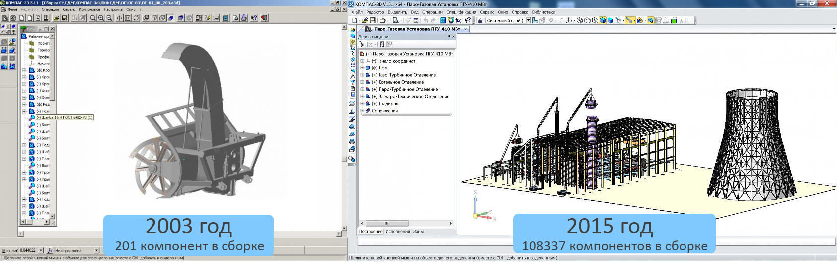
If 12 years ago there was enough work with assemblies of up to several thousand components, now KOMPAS users want to do complex projects for 300,000 components in an assembly, and some million will be few. The evolution of KOMPAS-3D user projects: on the left Snow-removing milling and rotor equipment for the K-700A, K-703MBA tractors , on the right the Steam-Gas Installation PGU-410 MW . If it is hard to see, click on the picture. In ServiceDesk - technical support - we received requests in the style of “I can’t open my factory in the morning” and “the model has opened, but it doesn’t rotate”. There is only one conclusion - COMPAS required serious revision.
The primary task is to increase system performance when working with large assemblies. And to increase not by conditional 10-30%, but several times.
To solve these problems, in 2015 we formed a working group to accelerate KOMPAS-3D. A kind of quick response squad of programmers, testers and analysts.

Our speed team
We have chosen 5 directions for acceleration:
When choosing these areas, we relied on several sources:

Here we are discussing something.
Together with the formation of the working group, we created our own information space - a knowledge base - we wrote down all the tasks there, collected and systematized ideas on possible areas of acceleration. As a result, requirements began to form with scenarios for further work, thanks to which it was possible to control performance.
Another axiom that we adopted while working on the version: productivity cannot be simply taken and improved, and then forgot about it. It was required to measure and record the current state, from which we could then repel. At that time, the starting point was version V16 (our story is still in 2015), which needed to be controlled by scripts from our TK. The performance of several key points was controlled manually, but now this process is automated thanks to the POI.
We decided to concentrate on real user models that fit the criteria of "large assemblies."
The database of models of the Computer 3D-modeling Aces Competition was of great benefit .
Below are screenshots of our favorite models. Of course, this is not all, and, moreover, we are confident that the top models of recent years will soon become familiar and KOMPAS will work with them not at the limit, but in its regular, high-speed mode.
When it was necessary to load the system even more, in addition to these models, peculiar “prefabricated hodgepodge” was also used, for example:
We also used synthetic models: in some cases, certain problems are more pronounced on them and they are more convenient to use for debugging and testing.
First of all, they tried to speed up the rendering (this was also requested by the majority of users who participated in the survey).
The rendering speed is critical in all processes where the model is positioned or its display changes. And this is not only the rotation, movement or zooming of the model. Rendering speed also matters in those processes where the model image is updated:
And these are far from all cases where the visualization subsystem is used. Therefore, it is clear why rendering acceleration has become a priority for us.
At the same time, it was important not only to use the capabilities of productive modern video cards, but also not to forget about those who use not so strong and modern hardware.
The result of the work was the implementation of two rendering options:
In the next part, we continue our story about rendering, and also show the results of measuring the rendering speed during assembly rotation, MTC calculations, adding components to the assembly, and tell about the appearance of a partial load type.
And for dessert, they left a video for you to compare the rendering speed during rotation, scaling and shift of the Reducer of a marine power plant.
The end of the first part. To be continued .
Patience cannot be accelerated
How did we understand that it was time to “speed up”?
If 12 years ago there was enough work with assemblies of up to several thousand components, now KOMPAS users want to do complex projects for 300,000 components in an assembly, and some million will be few. The evolution of KOMPAS-3D user projects: on the left Snow-removing milling and rotor equipment for the K-700A, K-703MBA tractors , on the right the Steam-Gas Installation PGU-410 MW . If it is hard to see, click on the picture. In ServiceDesk - technical support - we received requests in the style of “I can’t open my factory in the morning” and “the model has opened, but it doesn’t rotate”. There is only one conclusion - COMPAS required serious revision.
First changes
The primary task is to increase system performance when working with large assemblies. And to increase not by conditional 10-30%, but several times.
To solve these problems, in 2015 we formed a working group to accelerate KOMPAS-3D. A kind of quick response squad of programmers, testers and analysts.
Our speed team
HELP: we have been working on acceleration before - these are both optimizations and new functions that allow us to solve some of the problems when working with large assemblies. However, the tasks were not as ambitious as they are now, and the work was not so voluminous.
How did you choose the criteria for acceleration?
We have chosen 5 directions for acceleration:
- rendering (rotation, movement and zooming of the model image),
- adding components to a large assembly
- assembly opening
- editing in assemblies,
- projection.
When choosing these areas, we relied on several sources:
- own experience and research,
- analysis of requests for technical support and analysis of the error base (in our tools there is a special label “performance”, where problems critical for performance are noted),
- user survey results (users usually fill out such questionnaires at ASCON events),
higher powers.
Here we are discussing something.
Together with the formation of the working group, we created our own information space - a knowledge base - we wrote down all the tasks there, collected and systematized ideas on possible areas of acceleration. As a result, requirements began to form with scenarios for further work, thanks to which it was possible to control performance.
Another axiom that we adopted while working on the version: productivity cannot be simply taken and improved, and then forgot about it. It was required to measure and record the current state, from which we could then repel. At that time, the starting point was version V16 (our story is still in 2015), which needed to be controlled by scripts from our TK. The performance of several key points was controlled manually, but now this process is automated thanks to the POI.
Anton Sidyakin, programmer, teamlead:
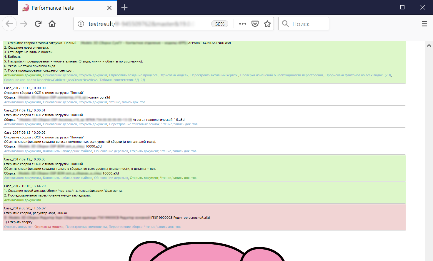
“We automated the processes thanks to the implemented system - POI (Points of Interests). These are special tags located in the source code. According to them, executing scripts in KOMPAS-3D described by the user language, you can get a report that is understandable not only to the programmer, but also to analysts with testers and helps to find out what KOMPAS-3D does at a certain moment and how much time is spent on it. Then this information can be processed automatically and compared with the source data. "
Results of automatic performance testing. By the way, who has read to this place now knows that the KDPV slab is a symbol of our accelerator team. They consider slow code as slow code)

What models were used for comparison?
We decided to concentrate on real user models that fit the criteria of "large assemblies."
The database of models of the Computer 3D-modeling Aces Competition was of great benefit .
Below are screenshots of our favorite models. Of course, this is not all, and, moreover, we are confident that the top models of recent years will soon become familiar and KOMPAS will work with them not at the limit, but in its regular, high-speed mode.
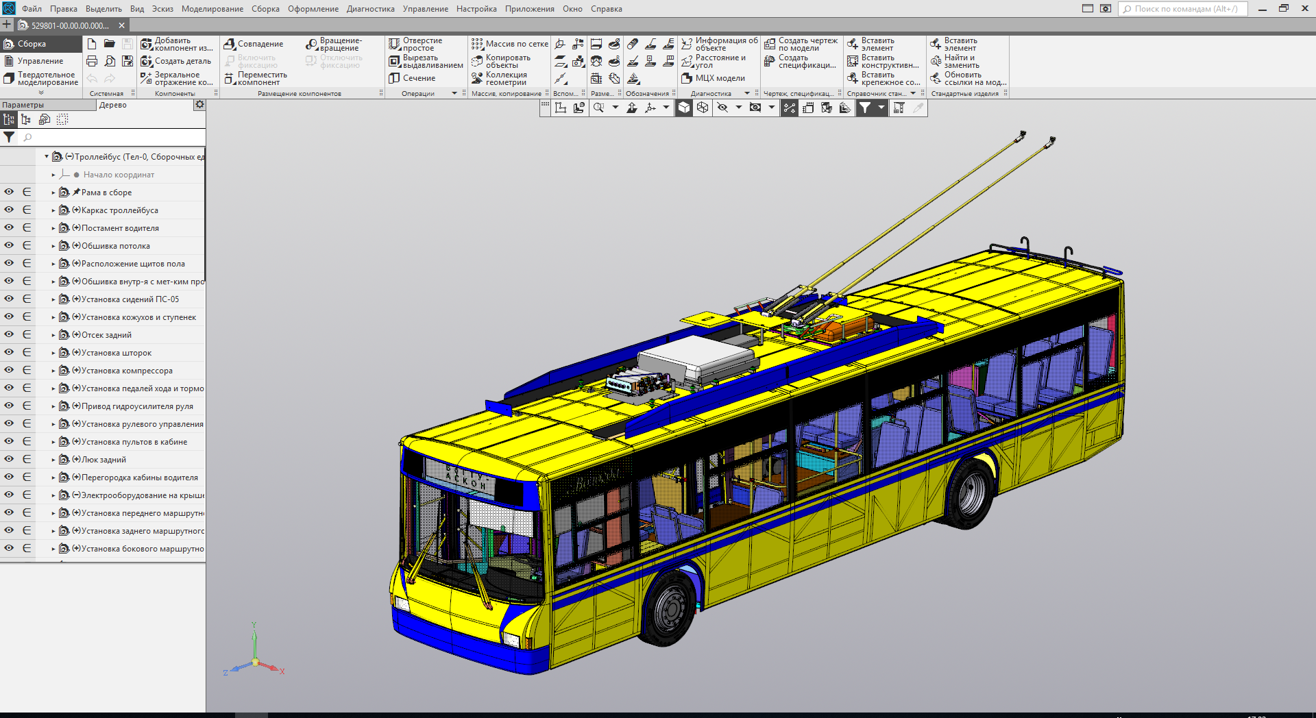 | 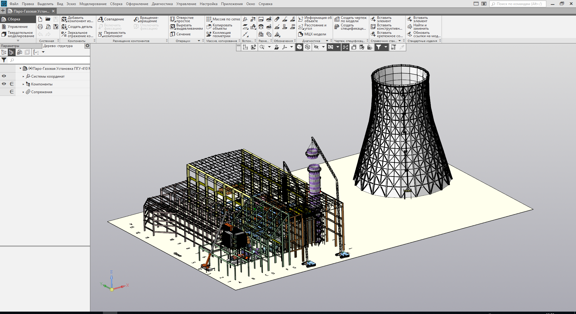 |
| Trolley bus | Steam-Gas Unit CCP-410 MW |
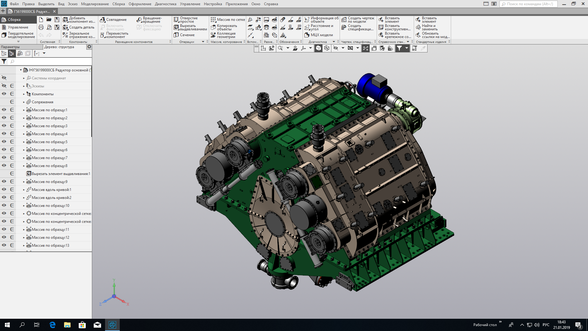 |  |
| Marine power plant gearbox | Vacuum technological installation |
When it was necessary to load the system even more, in addition to these models, peculiar “prefabricated hodgepodge” was also used, for example:
We also used synthetic models: in some cases, certain problems are more pronounced on them and they are more convenient to use for debugging and testing.
About development and results achieved
Drawing
First of all, they tried to speed up the rendering (this was also requested by the majority of users who participated in the survey).
The rendering speed is critical in all processes where the model is positioned or its display changes. And this is not only the rotation, movement or zooming of the model. Rendering speed also matters in those processes where the model image is updated:
- Adding a component to an assembly
- selection of basic objects for mates (faces, edges, etc.),
- highlighting of selected parts of the model (components, faces),
- change the visibility of objects (hide / show the component).
And these are far from all cases where the visualization subsystem is used. Therefore, it is clear why rendering acceleration has become a priority for us.
At the same time, it was important not only to use the capabilities of productive modern video cards, but also not to forget about those who use not so strong and modern hardware.
The result of the work was the implementation of two rendering options:
- Basic - Enables Open GL 2.0 extensions. Less demanding on video card performance. Gives good rendering acceleration,
- “Improved” - uses the modern extensions of OpenGL 4.5. Demanding on the characteristics of the video card. Gives maximum rendering acceleration on modern maps
Hint:
Render settings for v18.
By default, "Auto Detect" works - the desired option is selected based on the supported OpenGL extensions.
Render settings for v18.
By default, "Auto Detect" works - the desired option is selected based on the supported OpenGL extensions.
Yuri Korchagin, programmer:
“In the problem of the performance of displaying large scenes, it is clear that a lot of resources are spent on going around the scene and calculating the parameters with which the primitive should be displayed.
Another problem is associated with a large number of draw calls (calls to the OpenGL API, which lead to the output of geometry to the frame buffer).
The initial state also assumed the transfer of all data to the video card from RAM. And these are millions of triangles in the case of a large assembly.
Cosmetic corrections could not be dispensed with here, since a multiple increase in productivity was required. Therefore, it was decided to largely rewrite the visualization module.
The first step was to use video memory to cache drawing data (triangulation, wireframe, faces). By moving this data to the GPU, we managed to get a 2-3-fold increase in FPS.
This was followed by the creation of a data model adapted for visualization. That is, we got rid of requests for a 3D model, which can be quite resource intensive, which also gave its positive effect.
The next step was to study the quality and volume of triangulation. Often small details were displayed with excessive accuracy, and vice versa - in certain situations, instead of smooth surfaces, the user saw a “chopped” model on the screen.
We decided to use several levels of detail and apply the approximation of primitives taking into account the angular deviation. In this way, two birds with one stone were killed: they improved the quality and eliminated the excessive load on the GPU. "
Spoiler: About triangulation
Clarifies Nikita Batyanov, an analytical engineer:
“For a more correct and generally pleasant display of the models, we decided to supplement the triangulation parameters with the maximum angular deviation. Previously, we used only the maximum linear deviation parameter.
Let me remind you: in order for the video card to draw our theoretical representations of objects, it is necessary to break them into triangles. The more such triangles there are, the more the image will look like “ideal”, but the stronger the load on the video card will be.
The algorithm for breaking into triangles using the maximum angular deviation allows you to more accurately display some models, while not increasing the number of triangles as much as if only the maximum linear deviation were used.
"We can draw objects that are smaller relative to the dimensions of the entire model, while slightly overstating the number of triangles."
“Well, displaying the model has become faster, but not as much as we would like. At this stage, we realized that we couldn’t get more out of this approach.
On the other hand, the use of the latest approaches will require the most up-to-date video cards, which contradicts the compatibility requirements and some users will clearly not like it. Therefore, the improvements described above have become available as a “Basic” rendering option.
And then the fun began ... "
In the next part, we continue our story about rendering, and also show the results of measuring the rendering speed during assembly rotation, MTC calculations, adding components to the assembly, and tell about the appearance of a partial load type.
And for dessert, they left a video for you to compare the rendering speed during rotation, scaling and shift of the Reducer of a marine power plant.
The end of the first part. To be continued .