UDB. What is it? Part 4. Datapath ALU
- Transfer
As promised last time, we begin a detailed analysis of the Arithmetic Logical Unit (ALU).
Previous articles in the cycle:
UDB. What is it? Part 1. Introduction. Pld.
UDB. What is it? Part 2. Datapath
UDB. What is it? Part 3. Datapath FIFO.
21.3.2.4 Datapath ALU
The ALU core consists of three independent 8-bit programmable functions: an arithmetic / logic block, a shift register block, and a mask overlay block.
Arithmetic and logical operations
The ALU functions that are dynamically selected using the configuration RAM are shown in the table below.
Table 21-8. ALU functions.
| Func [2: 0] | Function | Operation |
|---|---|---|
| 000 | Pass | srca |
| 001 | INC | ++ srca |
| 010 | DEC | --srca |
| 011 | ADD | srca + srcb |
| 100 | SUB | srca - srcb |
| 101 | XOR | srca ^ srcb |
| 110 | AND | srca & srcb |
| 111 | OR | srca | srcb |
Carry in (Carry in)
Carry in is used in arithmetic operations. As shown in Table 21-9, for some functions, there are default carry in values.
Table 21-9. Functions Carry In.
| Functions | Operation | The default implementation of Carry In |
|---|---|---|
| INC | ++ srca | srca + 00h + ci, where ci is 1 |
| DEC | --srca | srca + ffh + ci, where ci is 0 |
| ADD | srca + srcb | srca + srcb + ci, where ci is 0 |
| SUB | srca - srcb | srca + ~ srcb + ci, where ci is 1 |
In addition to these standard arithmetic applications, there are three more options for using the transfer. The CI SELA and CI SELB bits define the use of the carry in input for each clock cycle. Dynamic configuration RAM selects configuration A or B per clock cycle. The parameters are given in table 21-10.
Table 21-10. Additional features Carry In.
| CI SEL A CI SEL B | Transfer mode | Description |
|---|---|---|
| 00 | Default (Default) | The default arithmetic mode is described in Table 21-9. |
| 01 | Snap (Registered) | A carry flag that is the result of a carry from the previous cycle. This mode is used for the implementation of operations of addition with transfer and subtraction with occupation. |
| ten | Forwarding (Routed) | The transfer is generated elsewhere and forwarded to this input. This mode can be used to implement managed counters. |
| eleven | Binding in the chain (Chained) | The transfer is placed in the chain after the previous Datapath. This mode can be used to implement single - cycle operations of higher bit depth, in which two or more Datapaths are used. |
If forwarding is used, it is used in a number of functions, as shown in Table 21-11. Note that for the decrement and subtraction functions of the unit, the active level of transfer is low (inverse).
Table 21-11. Functions traced Carry In.
| Function | Polarity Carry In | Carry In is active | Carry In is inactive |
|---|---|---|---|
| INC | Straight | ++ srca | srca |
| DEC | Inverse | --srca | srca |
| ADD | Straight | (srca + srcb) +1 | srca + srcb |
| SUB | Inverse | (srca - srcb) -1 | (srca - srcb) |
Carry Out
Carry out is an optional Datapath output based on a statically defined high bit. The value can be transferred along the chain to the transfer input to a higher block. Note that in the case of the decrement and subtraction functions, carry out is inverted.
Table 21-12. Functions Carry Out.
| Function | Polarity Carry Out | Carry Out is active | Carry Out is inactive |
|---|---|---|---|
| INC | Straight | ++ srca == 0 | srca |
| DEC | Inverse | --srca == -1 | srca |
| ADD | Straight | srca + srcb> 255 | srca + srcb |
| SUB | Inverse | srca - srcb <0 | (srca - srcb) |
Transfer structure
The carry in parameters and to select the high-order bit, to generate carry out, are shown in Figure 21-15. The snap-in carry out values can be used as carry in for subsequent arithmetic operations. This feature can be used to implement functions of higher bit depth using cycles.
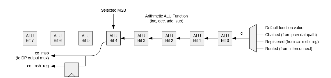
Figure 21-15. Transfer operation
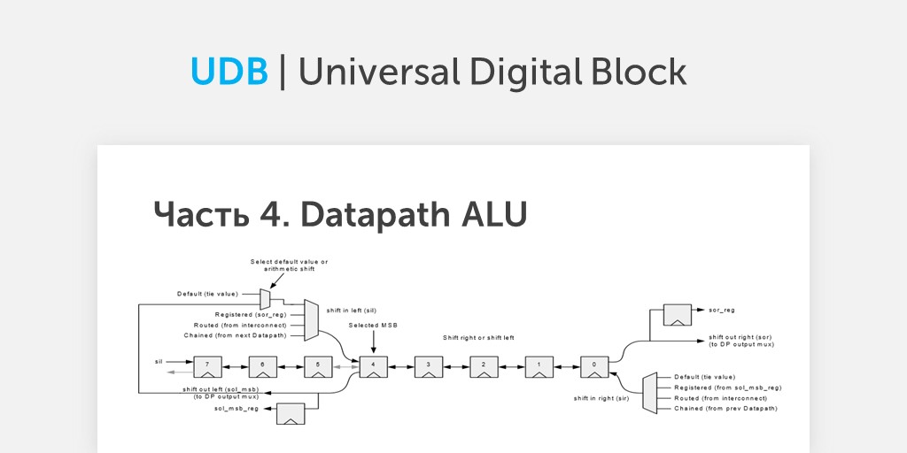
Shift operation
The shift operation occurs independently of the work of the ALU, according to Table 21-13.
Table 21-13. The functions of the shift operation.
| Shift [1: 0] | Function |
|---|---|
| 00 | Pass (Pass) |
| 01 | Shift Left (Shift Left) |
| ten | Shift Right (Shift Right) |
| eleven | Nibble Swap (Nibble Swap) |
The output value of the shift operation is issued from the Datapath. Setting the outputs for the shift to the right ( sor ) and to the left ( sol_msb ) is performed by the same bits. The static configuration bit (SHIFT SEL in the CFG15 register) determines which shift output is used as the Datapath output. In the absence of a shift, the signals sor and sol_msb are defined as LSB and MSB ALU functions, respectively.
The SI SELA and SI SELB configuration bits define the data shift for the specified operation. Dynamic configuration RAM selects configuration A or B for each clock cycle. The moved data is used only when shifting left and right, this input is not used when skipping and rearranging nibbls. Selected values and use cases refer to both the right shift and the left shift and are shown in Table 21-14.
Table 21-14. Shift in functions
| SI SEL A SI SEL B | Source pushed data | Description |
|---|---|---|
| 00 | Default / Arithmetic (Default / Arithmetic) | By default, the value of the DEFSI bit (constant 1 or 0). However, if MSB SI is set, then the source is the value of the selected high bit of the ALU (only for shifts to the right). |
| 01 | Snap (Registered) | The input value for the shift is given by the currently latched output value of the shift (from the previous cycle). The left shift operation uses the last left shift value . The right shift operation uses the last output right shift value. |
| ten | Forwarding (Routed) | The input to the shift comes from the outside, through the trace resources (input SI). |
| eleven | Binding in the chain (Chained) | For the input shift to the left, it is forwarded from the output of the right Datapath block in the chain, for the input shift to the right - from the left. |
The output for the left shift is taken from the bit specified as the highest. When shifted to the right, the input data pushes, starting at the selected highest (MSB) position. The output data, even when shifting to the left, even if shifting to the right, snaps into place and can be used on the next clock cycle. This feature can be used to implement a higher-resolution shift in multiple cycles.

Figure 21-16. Shift operation
It is worth noting that the isolated bits of the MSB are still shifted. In the example shown, bit 7 is still shifted by the value of sil when shifted to the right, and bit 5 is shifted to bit 4 when shifted to the left. The output (right or left) bit of the isolated group will be lost.
ALU mask overlay operation
The 8-bit masking register in the static space of the UDB configuration registers defines the mask mapping operation. In this operation, a mask (AND operation) is applied to the ALU output with the value of this register. A typical use of the ALU mask overlay operation is the implementation of autonomous timers and counters with a resolution that is a multiple of a power of two.
21.3.2.5. Datapath Inputs and Multiplexing (Datapath Inputs and Multiplexing)
As shown in Table 21-15, each Datapath has 9 inputs, including 6 inputs from channel tracing. These include addresses of the configuration of RAM, FIFO, data load control signals for the data registers, as well as the shift and transfer of data inputs.
Table 24-15. Inputs Datapath.
| entrance | Description |
|---|---|
| RAD2 RAD1 RAD0 | Asynchronous address in dynamic configuration RAM. It addresses eight user-programmable 16-bit words. Each word contains the Datapath control bits for the current cycle. The sequence of instructions can be determined by these address inputs. |
| F0LD F1LD | If it is cocked in this cycle, the data from the A0 or A1 battery or the output data from the ALU are loaded into the selected FIFO . The source is selected using the Fx INSEL [1: 0] configuration bits. This input is sensitive to overshoot. It is sampled at the Datapath clock; when a transition from “0” to “1” is detected , loading occurs on the next clock edge. |
| D0LD D1LD | If cocked in this loop, the Dx register is loaded from its associated FIFO Fx. This input is sensitive to overshoot. It is sampled at the Datapath clock; when a transition from “0” to “1” is detected, loading occurs on the next clock edge. |
| SI | This is a data entry value that can be used to shift to the right or left. |
| CI | This transfer value is used if the transfer control signal is “routed carry”. |
As shown in Figure 21-17, each input has a 6-in-1 multiplexer, therefore all inputs are interchangeable. Inputs are processed in two ways: either by level or by differential. The address in the dynamic configuration memory, as well as the offset and data values are level sensitive. FIFO and data register load signals are sensitive to ramps.

Figure 21-17. Datapath input signals.
In the next article we will move on to a review of useful things.