Features of the formation of clock frequencies in PSoC 5LP
When developing the hardware of the REDD complex described in this article , we considered various implementation options. PSoC was considered, because for it there is a ready-made relatively standardized, albeit de facto, version of the USB-I2C adapter. Unfortunately, for the reasons described in the article about DMA , it was not possible to do something difficult for this particular complex on the PSoC, and simple is not economically feasible. It turned out to be cheaper to take chips from FTDI. But while experiments were being conducted with PSOC, interesting details were revealed that it makes sense to publish.
Core experience
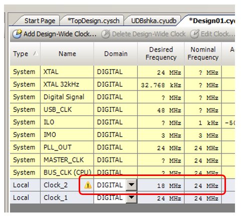
Let's make a simple project. Let us configure the timing of its blocks as follows:
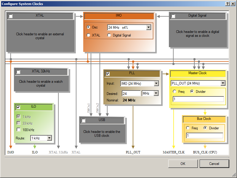
The PLL has the lowest possible frequency selected (the development environment will not give less). The bus is clocked by it. This is done intentionally. The results of the work will be controlled by the oscilloscope, and in the comments to this article I showed that it is better not to get closer to the upper limit of the passband, especially if the oscilloscope is Chinese: the fronts will be so blocked that you can make a mistake in the measurements. So it’s better to take a lower frequency. The minimum is 24 MHz, and we take it.
The design scheme is trivial. Two sources of clock pulses connected to the legs of the chip.
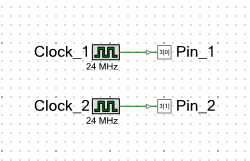
Document AN60631 says that the system will make the frequencies of Clock_1 and Clock_2 sources from the base, passing through the dividers:
In our project, we will always send a signal with a frequency of 24 MHz to the Pin_1 leg, and try to send a signal of a lower frequency to Pin_2. At first everything goes predictably. With the desired frequency from 23 to 18 MHz, we get an achievable equal to 24.
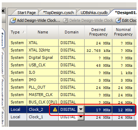
By lowering the desired frequency to 17 MHz, we get an achievable 12. Everything is logical. The divider is not PLL. The division constant must be integer. Just made sure that there are no surprises.
Set the desired frequency to 12 MHz. We are assembling a project (no code is required to write) and look at the result.
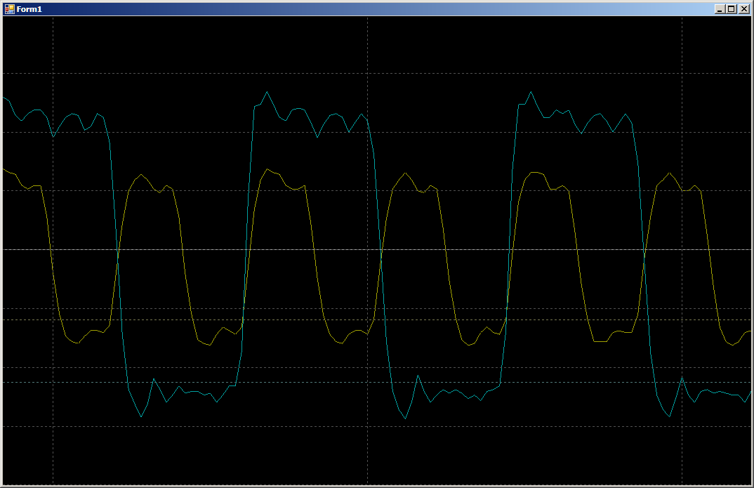
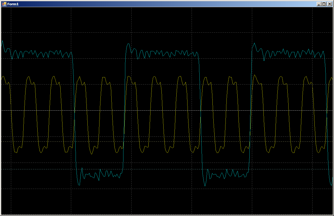
The yellow beam is the base frequency, the blue is divided. Again no catch. So what is the purpose of the article? We are just getting to the most interesting. What is the next division factor? Troika. The next achievable frequency is 24/3 = 8 MHz. We change the settings of the project, “flash” it, look ...
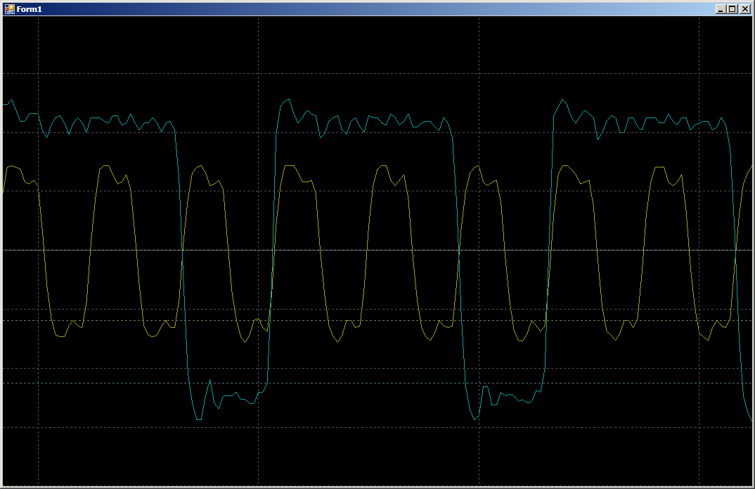
Please love and favor, on a blue ray a clock signal with a duty cycle other than 50% is visible. Does a simple programmer expect a clock source to give him this? Unlikely. But he issued it.
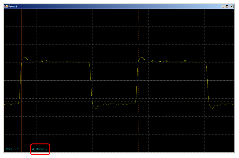
Division by 4 is predictably beautiful. We check the division by 5 (the desired frequency is 4.8 MHz):
The trend is clear. The PWM is clearly playing the role of a divider. The higher the odd division ratio, the closer the duty cycle will be to 50%, but in general, there will still be some discrepancies between the positive and negative half-periods. If the circuit is clocked only by positive fronts, then this is not scary. But if the developer made some component of his own, in which both positive and negative edges of the clock signal are used, nuances are possible, and sometimes there are floating failures.
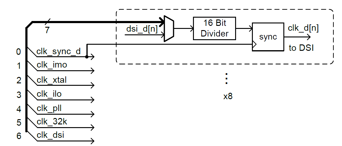
In general, this case is more or less described in TRM in Figure 14-12, so again, no one hides anything:
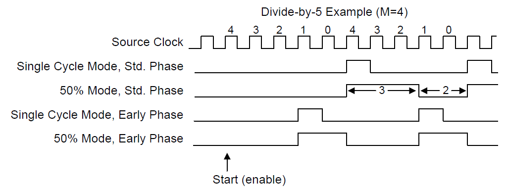
But something tells me that few people will study this pattern before they catch the corresponding picture on the oscilloscope. And he will catch her only after lengthy attempts to find out why the system crashes. Therefore, I consider it necessary to warn about this feature of the Clock component of PSoC.
Additional PSoC Clock Information
The temperature dependence of the frequency of the internal generator
It turned out somehow very briefly. Let's explore one more issue related to clock speed. Once upon a time, I was doing one project on AtMega8. To reduce the cost of the system, the clock was taken from an internal generator. The project was debugged at the stand, but after that it turned out that when the board gets into the target environment, it only works correctly after turning on the power. After a couple of minutes, everything heats up, the frequency floats away and the received serial data starts to decode incorrectly. And if you adjust the shelters under this mode - everything lies before warming up. In that project, everything was decided safely: the data was in the Manchester code, and it was self-synchronizing. I just did the synchronization not from the start of the package, but from each bit. But for the future I learned that when using internal generators in controllers, it is necessary to check their thermal stability. We’ll check it with PSoC, since there is no quartz resonator on the existing breadboard, so the system is clocked from the internal oscillator located in the controller. The controller itself, for my tasks, has not yet heated up for me, but it can be heated by components located on the same board.
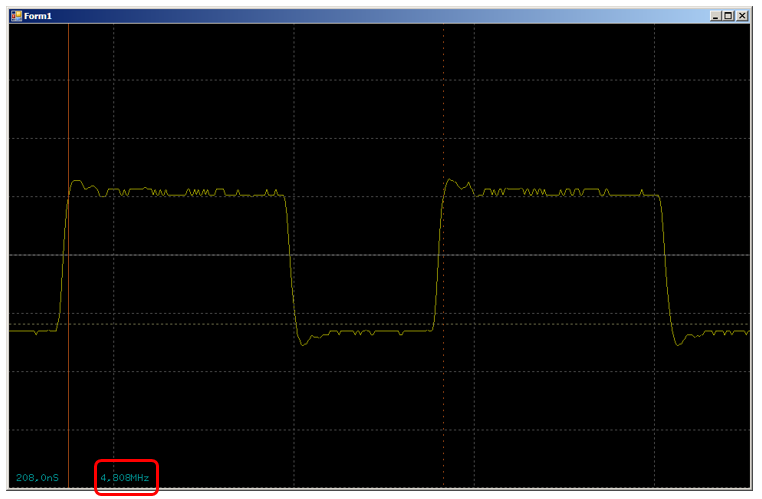
At a frequency of 24 MHz, the fronts are quite rounded, you can make a mistake. Let us take for experiments the obtained frequency f / 5.
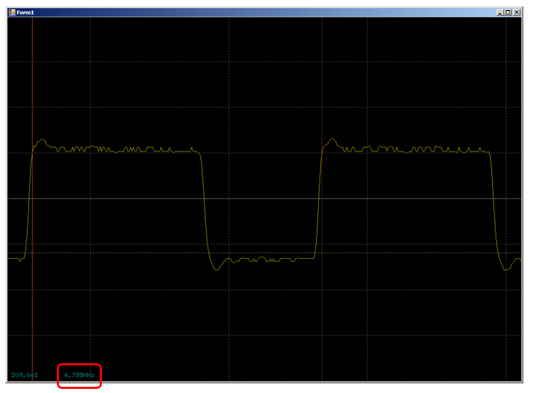
By the way, this is not quite 4.8, but rather 4.78 MHz. No problem! The generator can be calibrated! AN60631 says that in general, an 11-bit register located in the ports IMO_TR0 and IMO_TR1 is responsible for this. How to automatically calculate its optimal value using an external reference generator is described in document CE219322. An example is even attached to that document. But on my breadboard there is no separate generator, so for one instance it was easier for me to select the value empirically, focusing on the readings of the oscilloscope. Adding the following code to the main () function (increment step is 0x20, since the lower 5 bits are not used):
    volatile uint16_t* ptr = (uint16_t*) CYREG_IMO_TR0;
    ptr[0] += 20 * 0x20;
I achieved quite a decent result:
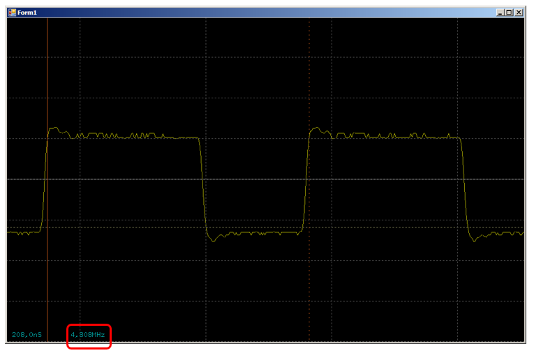
We will hold the board on the balcony, where today it is about zero. The frequency swam off a little, but on an existing oscilloscope it is even difficult to measure. Rather visible by eye (at the intersection of the left cursor with the yellow beam).
Now we heat the board on the battery. Also on the device differences are not visible.
So in PSoC the generator is quite thermostable. Raging departures of the frequency at which the working system begins to give big errors should not be expected from him.
The dependence of the frequency of the internal generator on the supply voltage
I already wrote this article and gave it for a rough reading, as another interesting factor surfaced related to the clock frequencies. On one project, the frequency measurement went with an error of about 2%, which is essential for that task. Moreover, the logic implemented in UDB was implemented correctly. There were no errors in the logic. Controlling everything with an oscilloscope, I noticed that the reference frequency is lying at just those 2%.
But why? Still it was wonderful! It was then that I recalled the draft article. The dependence is not only on temperature, but also on the supply voltage. And at some point I lowered it from 5 to 3.3 volts. Calibrated the frequency of the generator, the error is gone.
But after that there was a desire to find dependencies in the documentation. It turns out that they are all listed in the DataSheet for a specific chip. Here is the temperature dependence of the generator error.
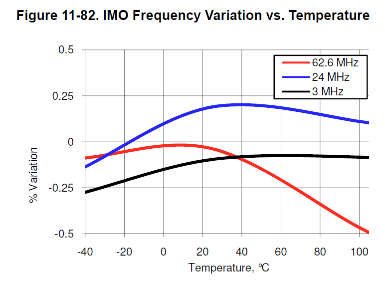
My graph is blue. In general, everything is consistent with practical results. And here is the voltage dependence:
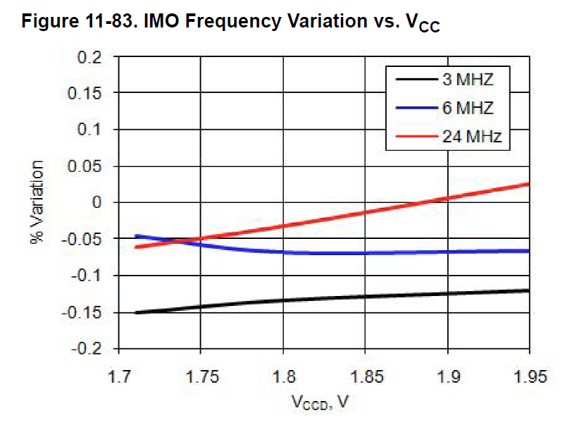
Here, the required graph for some reason is red. At two percent, he clearly does not pull, but a linear increase in the error is evident.
Conclusion
When using the standard Clock component in PSoC Creator, you should be prepared for the fact that the duty cycle of the pulses there will not be 50%. This is important if the project uses not only fronts, but also signal slices. To combat this effect, you should divide the base frequency by even coefficients.
For applications that are sensitive to frequency errors, the internal clock (IMO) is recommended to be used only with a stabilized supply voltage, and for each specific product after assembly, it is recommended to calibrate the frequency. If battery unstabilized power is expected, it is best to use an external quartz resonator.