Visual Programming for Sonoff Basic
- Tutorial
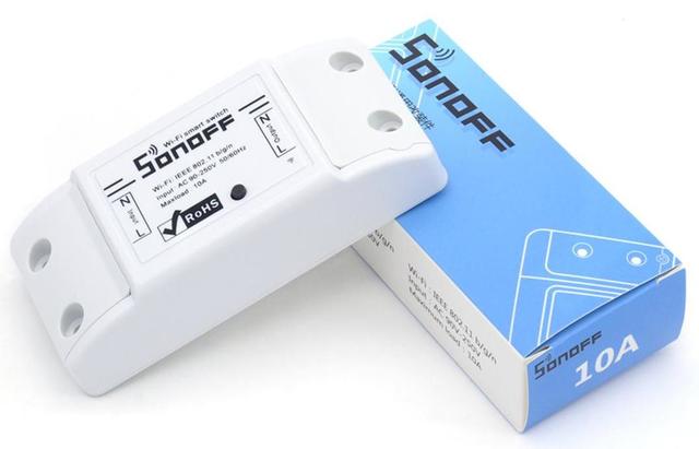
An article on how to create a programmable logic controller from a cheap Chinese device. Such a device will find its application both in home automation and as a practical lesson in school computer science.
For reference, by default, the Sonoff Basic program works with a mobile application through the Chinese cloud service, after the proposed alteration, all further interaction with this device will become possible in the browser.
Section I. Connecting Sonoff to MGT24
Step 1. Create a control panel
Register on the mgt24 website (if you have not registered yet) and log in under your account.
Login
To create a control panel for a new device, click on the "+" button.
Panel Creation Example
After the panel is created, it will appear in the list of your panels.
In the “Installation” tab of the created panel, find the “Device ID” and “Authorization Key” fields, in the future, this information will be required when setting up the Sonoff device.
Tab Example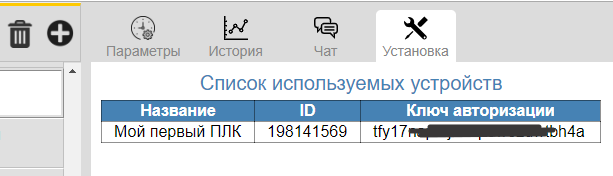
Step 2. Flashing the device
Using the XTCOM_UTIL utility , download the Sonoff Basic PLC firmware to the device, for this you need a USB-TTL converter. Here is the instruction and video instruction .
Step 3. Configure the device
Apply power to the device, after the LED lights up, press the button and hold it down until the LED starts to periodically flash evenly.
At this point, a new wi-fi network called “PLC Sonoff Basic” will appear, connect your computer to this network.
Decoding LED indication
| LED indication | Device status |
|---|---|
| periodic double flashing | no connection with the router |
| shines continuously | established connection with the router |
| periodic uniform flashing | wifi access point mode |
| put out | no power |
Open an Internet browser and enter the text “192.168.4.1” in the address bar, go to the device’s network settings page.
Fill in the fields as follows:
- “Network Name” and “Password” (to bind the device to your home wi-fi router).
- “Device ID” and “Authorization Key” (to authorize the device on the MGT24 service).
Example of setting device network parameters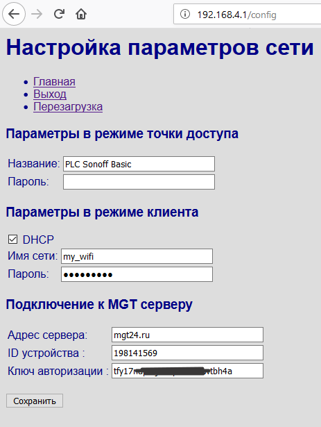
Save the settings and reboot the device.
Here is a video tutorial .
Step 4. Connecting sensors (optional)
Current firmware supports up to four ds18b20 temperature sensors. Here is a video tutorial on mounting sensors. Apparently, this step will be the most difficult, as it will require direct hands and a soldering iron.
Section II. Visual programming
Step 1. Scripting
Blockly is used as the programming environment, the environment is easy to learn, so you do not need to be a programmer to create simple scripts.
I added specialized blocks for writing and reading device parameters. Access to any parameter is carried out by name. Compound names are used for remote device parameters: “parameter @ device”.
Drop-down list of options
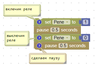
An example of a scenario of cyclic switching on and off a load (1Hz):
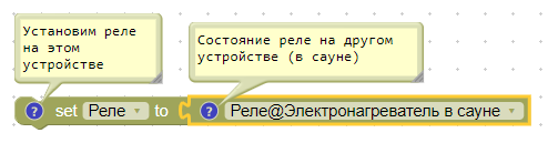
An example of a scenario synchronizing the operation of two separate devices. Namely, the relay of the target device repeats the operation of the relay of the remote device.
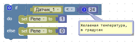
Script for the thermostat (without hysteresis):
To create more complex scenarios, you can use variables, loops, functions (with arguments) and other constructions. I will not describe all this in detail here, the network already has quite a lot of training material about Blockly .
Step 2. Scripting Order
The script runs continuously, and as soon as it reaches its end it starts again. There are two blocks that can temporarily suspend the script, “delay” and “pause”.
The delay block is used for millisecond or microsecond delays. This unit strictly maintains the time interval, blocking the operation of the entire device.
The pause block is used for second (maybe less) delays, and it does not block the execution of other processes in the device.
If the script within itself contains an infinite loop, in the body of which there is no “pause”, the interpreter independently initiates a small pause.
If the allocated memory stack is exhausted, the interpreter will stop the execution of such a voracious script (be careful with recursive functions).
Step 3. Debugging Scripts
To debug a script already loaded into the device, you can run the program trace in steps. This can be extremely useful when the behavior of the script is not what the author intended. In this case, tracing allows the author to quickly find the source of the problem and fix the error in the script.
Scenario for calculating factorial in debug mode:
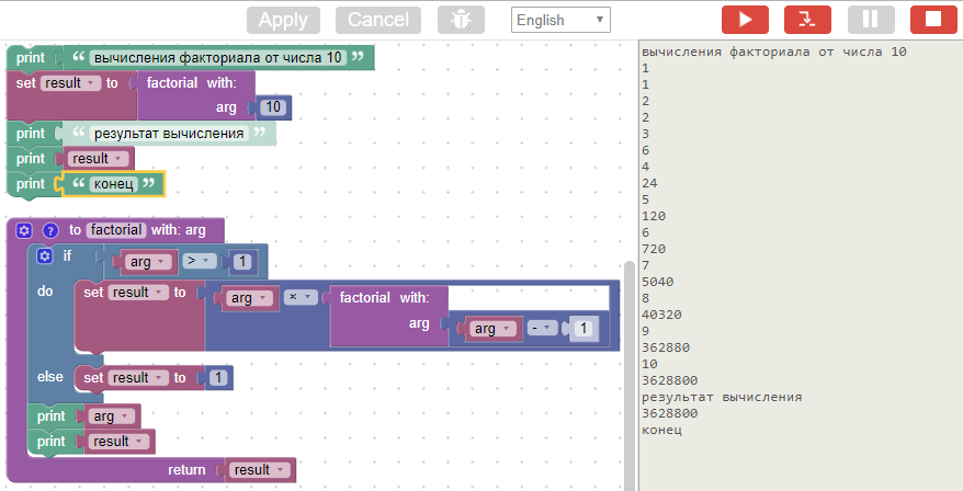
The debug tool is very simple and consists of three main buttons: “start”, “one step forward” and “stop” (we also will not forget about “entering” and “exiting” from debug mode). In addition to step-by-step tracing, you can set a breakpoint on any block (by clicking on the block).
To display the current values of parameters (sensors, relays) in the monitor, use the print block.
Here's an overview video on using the debugger.
Section for the curious. But what's under the hood?
In order for the scripts to work on the target device, a bytecode interpreter and an assembler for 38 instructions were developed. A specialized code generator was built into the blockly source code that converts visual blocks into assembler instructions. In the future, this assembler program is converted to bytecode and transferred to the device for execution.
The architecture of this virtual machine is quite simple and there is no sense in describing it; on the net you will find many articles on the design of simple virtual machines.
For the stack of my virtual machine, I usually allocate 1000 bytes, this is enough with a margin. Of course, deep recursions can exhaust any stack, but they are unlikely to find practical application.
The resulting bytecode is pretty compact. As an example, the bytecode for calculating the same factorial is only 49 bytes. This is his visual representation:

And this is his assembler program:
shift -1
ldi 10
call factorial, 1
print
exit
:factorial
ld_arg 0
ldi 1
gt
je 8
ld_arg 0
ld_arg 0
ldi 1
sub
call factorial, 1
mul
ret
ldi 1
ret
If the assembler representation form does not have any practical value, then the javascrit tab, on the contrary, gives a more familiar look than visual blocks:
function factorial(num) {
  if (num > 1) {
    return num * factorial(num - 1);
  }
  return 1;
}
window.alert(factorial(10));
As for performance. When I started the simplest flasher scenario, on the oscilloscope screen I got a 47kHz meander (at a processor clock speed of 80MHz).

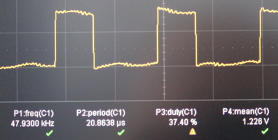
I think this is a good result, at least this speed is almost ten times faster than that of Lua and Espruino .
Final part
To summarize, I’ll say that the use of scripts allows us not only to program the logic of an individual device, but also makes it possible to link several devices into a single mechanism, where some devices influence the behavior of others.
I also note that the chosen method of storing scripts (directly in the devices themselves, and not on the server), simplifies switching existing devices to another server, for example, to the home Raspberry, here is the instruction .
That's all, I will be glad to hear advice and constructive criticism.