PCB Factory. Garage development and production of electronics. Ch2
- Tutorial
Real projects are born in the garage!
In the first part , the process of designing a board in CAD EAGLE was described in detail, with all the details, in the pictures. At the garage factory worked "design department." Now we transfer the documentation to the “manufacturers"
3D milling machine is ready! We look at the comics about the work of the “production department”)
To create g-code in the main Eagle window with the brd file open, right-click on pcb-gcode-setup.ulp and select Run in Board.

The settings window opens.
Parameter description:

Generation Options tab
Generate bottom outlines - the “Milling” board contour processing code is generated;
Generate bottom drills - the hole drilling code is created
Generate Milling - milling depth from 0 position according to Z
Spot drill holes - depth of drilling holes with a mill, which is used to process tracks. Since a V-shaped engraver is used for this, it is impossible to drill to a greater depth. Therefore, the depth is the same as for milling. In this case there will be a “punching” of the holes.
“Isolation” “Single pass” - a single processing of the contour of the track at a distance of 0.1 from it
“Etching Tool Size” - the diameter of the lower part of the engraver. If there is a beating of the engraver, then you need to take it with a margin, but with large values, the program will not be able to separate close tracks.
“Machine” tab “
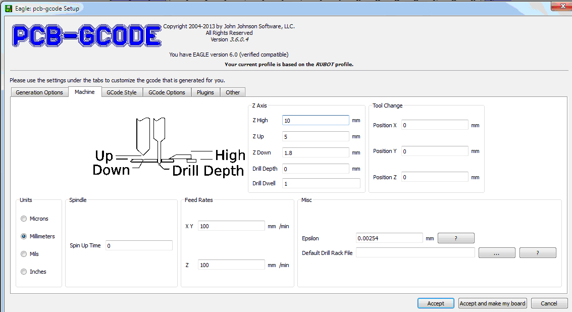
Units” - units of measure
“Feed rate” - speed of movement along XY and Z
“Z axis” - settings of milling and drilling
“Z high” - the height of the fasteners on the desktop
“Z up” - the height to which the engraver (drill) will rise when moving from one milling element to another
“Z down” - the milling depth from 0 position along the Z
“Drill depth” - drilling depth. Through and through, respectively. This parameter will be used to create a separate drilling file, which is launched after changing the engraver to a drill.
Gcode style tab.
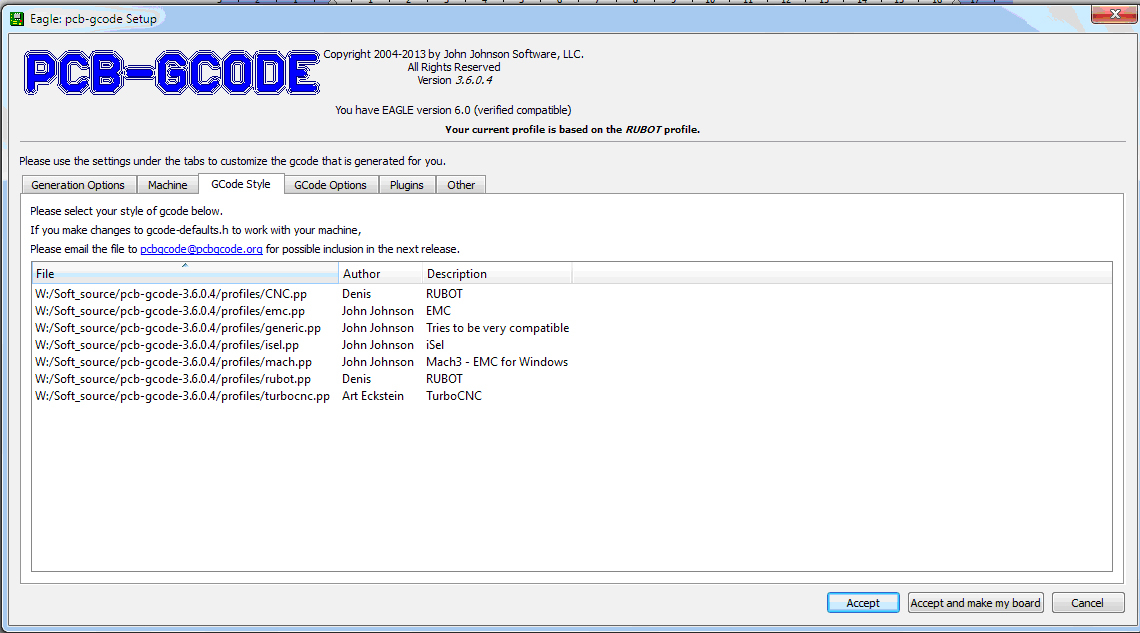
Here you select a profile for a specific machine.

The g-code view is configured in this file.
Gcode options tab

Advanced settings for g-code.
The “Use user gcode (from user-gcode.h)” flag is of interest here.
In this file, additional settings for creating g-code
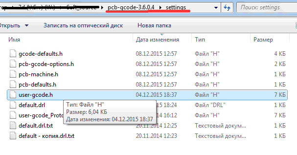
You can configure additional commands in this file.

In this case, commands are written that will be added to the beginning of each generated code.
G92 Z2 - Forces the coordinate in Z = 2 mm. Used during height calibration at the beginning of milling and drilling. When the engraver (drill) is brought in tight to the board and the code is run, the Z coordinate becomes equal to 2. Accordingly, when milling tracks, 0.2 mm (2.0-1.8) will be cut, when milling the contour and “punch” holes 0.5 mm (2.0-1.5 ) Drilling will be carried out to the entire depth of the board 2 mm.
G1 Z5 F100 - lifting the tool to a height of 5 mm to determine the coordinates in Y and X.
G28 Y - search 0 in the Y coordinate
G28 Y - then in the X coordinate
To save changes and create files, click “Accept and make my board”.
In the folder where the board file (brd) is saved, the files will be created:
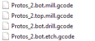
* .bot.mill.gcode - milling the circuit outline
* .top.mill.gcode - that- the same thing, but for the top of the board (this file is not needed)
* .bot.drill.gcode - drilling holes (the parameters are verified in the default.drl file)
* .bot.etch.gcode - milling the board tracks

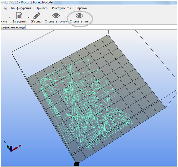
When opening (etch) file in the Repetier-Host (path visualization must be enabled), the milling path is displayed.
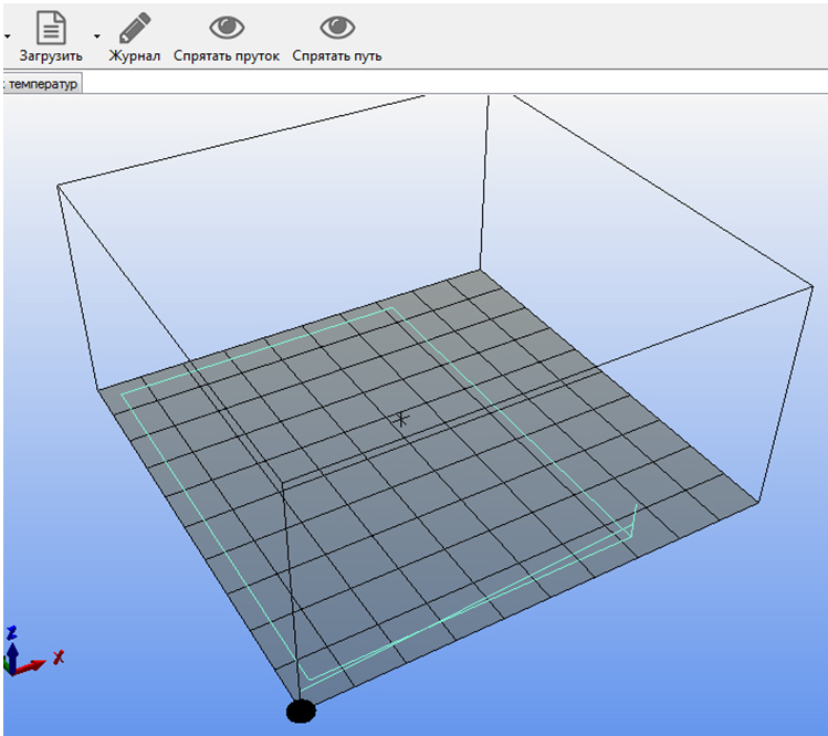
When you open the file (bot.mill), the milling of the circuit of the board is displayed.
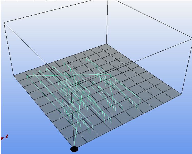
When you open the file (drill), it displays Drilling holes
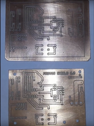
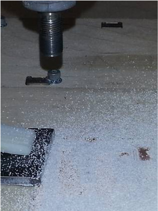
Milling a board
A V-shaped engraver is used for milling.
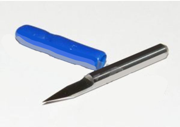
For example, a conic carbide engraver J32002: angle 20 degrees, shelf 0.2 mm, shank 3.175 mm, length 30 mm.
Important! When installing an engraver, it is necessary to achieve a lack of runout. It is checked when the spindle is on.
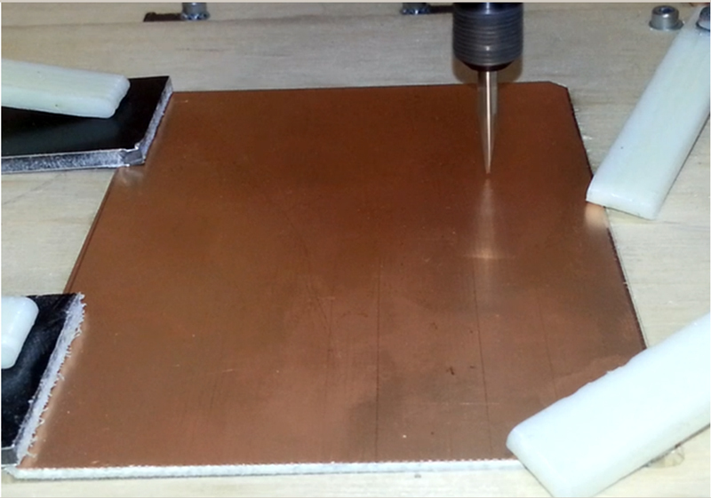
The board blank is installed.
The router is connected to the Repetier-Host.
We park along the Y axis, then along the X axis We
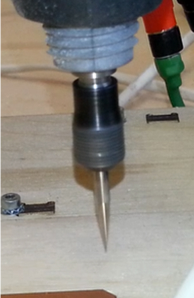
clamp the engraver until it falls out, but can move in the collet.
The blank of the board should not prevent the engraver from dropping to the 0 position (touching the table).
Then we park along the Z axis.
When the engraver rests on the table, he will shift in the collet and take the 0 position.
Raise Z 20 mm and tighten the collet.
We move the engraver to the center of the board.
We lower it until the foil touches (we use paper when it pierces, it will touch the foil)

Download the * .bot.etch.gcode file
In the code, the first lines:
G92 Z2 - force coordinate assignment to Z = 2
G1 Z5 F100 - rise Z to 5 mm, so that the engraver would not catch the board
G28 Y - parking on Y
G28 X - parking on X
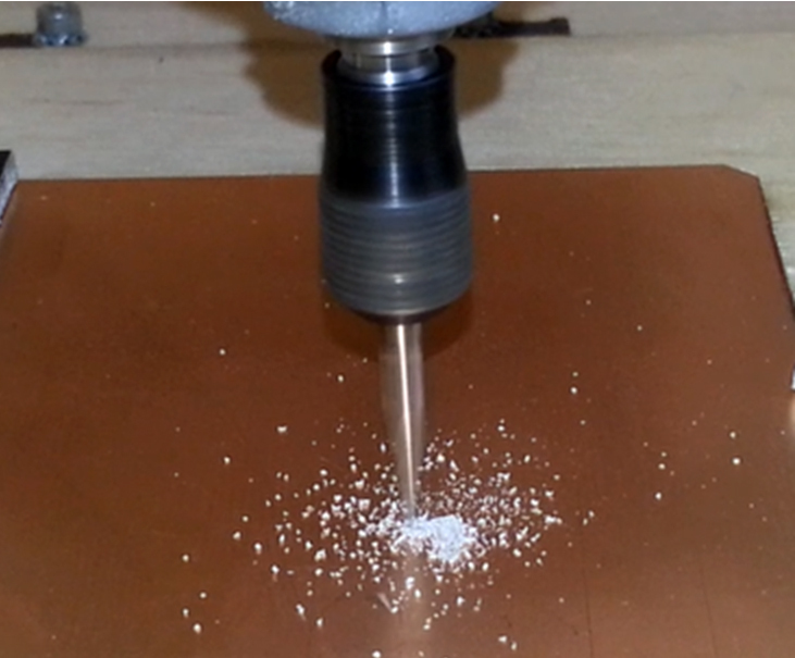
Run the code, remove the paper, turn on the spindle.
Board processing will begin.
After processing, the machine does not turn off.
Download the * .bot.mill.gcode file
Delete the lines:
G92 Z2
G1 Z5 F100
G28 Y
G28 X
G90; set positioning to absolute
G21; set units to millimeters
; (Beginning of every bottom file)
; (Outline Begin)
; (Bottom outline Begin)
; (Metric Mode)
G21
; (Absolute Coordinates)
G90
G0 X0.0000 Y0.0000
We start milling. The circuit milling will be carried out.
After the end of the milling, the machine does not turn off.
Turn off the spindle.
Remove the engraver.
!!! It is necessary to carry out the operations of replacing the engraver with a drill so as not to displace the spindle, as this will leave the drilling coordinates.
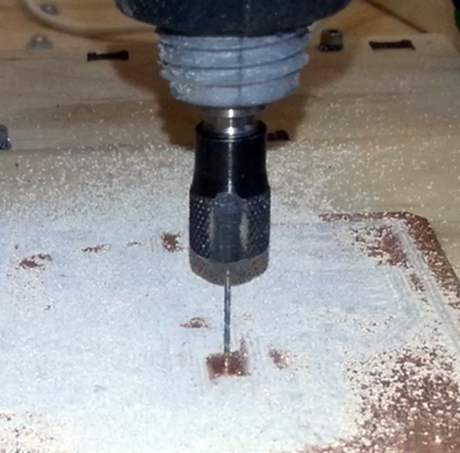
We put a drill of 0.8 mm.
Clamp the drill until it falls out, but can move in the collet.
Using the buttons in the program, we bring the drill to the center of the board and lower it along Z to the coordinate 2 mm. The drill bit will shift in the collet and will take a height of 2 mm from the table (0 position).
Clamp the collet.
Download the * .bot.drill.gcode file;
Delete lines:
G92 Z2
G1 Z5 F100
G28 Y
G28 X
G90; set positioning to absolute
G21; set units to millimeters
; (Beginning of every bottom file)
; (Beginning of All Drill files)
; (Bottom Drill Begin)
; (Tool | Size | Min Sub | Max Sub | Count)
; (; T01 | 1.000mm 0.0394in | 0.0236in | 0.1437in | 91)
; (Metric Mode)
G21
; (Absolute Coordinates)
G90
; (Tool Change Begin)
; (Bottom Tool Change Begin)
; M05
; G0 Z0.0000
G0 X0.0000 Y0.0000
Turn on the spindle and start drilling.
After drilling, turn off the spindle, remove the board.
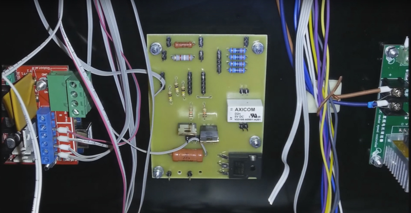
Sand, tin, install and solder the elements. Turn on. Rejoice!
ps
3D milling machine from Master Kit.
3D printers from Master Kit.
In the first part , the process of designing a board in CAD EAGLE was described in detail, with all the details, in the pictures. At the garage factory worked "design department." Now we transfer the documentation to the “manufacturers"
3D milling machine is ready! We look at the comics about the work of the “production department”)
To create g-code in the main Eagle window with the brd file open, right-click on pcb-gcode-setup.ulp and select Run in Board.
The settings window opens.
Parameter description:
Generation Options tab
Generate bottom outlines - the “Milling” board contour processing code is generated;
Generate bottom drills - the hole drilling code is created
Generate Milling - milling depth from 0 position according to Z
Spot drill holes - depth of drilling holes with a mill, which is used to process tracks. Since a V-shaped engraver is used for this, it is impossible to drill to a greater depth. Therefore, the depth is the same as for milling. In this case there will be a “punching” of the holes.
“Isolation” “Single pass” - a single processing of the contour of the track at a distance of 0.1 from it
“Etching Tool Size” - the diameter of the lower part of the engraver. If there is a beating of the engraver, then you need to take it with a margin, but with large values, the program will not be able to separate close tracks.
“Machine” tab “
Units” - units of measure
“Feed rate” - speed of movement along XY and Z
“Z axis” - settings of milling and drilling
“Z high” - the height of the fasteners on the desktop
“Z up” - the height to which the engraver (drill) will rise when moving from one milling element to another
“Z down” - the milling depth from 0 position along the Z
“Drill depth” - drilling depth. Through and through, respectively. This parameter will be used to create a separate drilling file, which is launched after changing the engraver to a drill.
Gcode style tab.
Here you select a profile for a specific machine.
The g-code view is configured in this file.
Gcode options tab
Advanced settings for g-code.
The “Use user gcode (from user-gcode.h)” flag is of interest here.
In this file, additional settings for creating g-code
You can configure additional commands in this file.
In this case, commands are written that will be added to the beginning of each generated code.
G92 Z2 - Forces the coordinate in Z = 2 mm. Used during height calibration at the beginning of milling and drilling. When the engraver (drill) is brought in tight to the board and the code is run, the Z coordinate becomes equal to 2. Accordingly, when milling tracks, 0.2 mm (2.0-1.8) will be cut, when milling the contour and “punch” holes 0.5 mm (2.0-1.5 ) Drilling will be carried out to the entire depth of the board 2 mm.
G1 Z5 F100 - lifting the tool to a height of 5 mm to determine the coordinates in Y and X.
G28 Y - search 0 in the Y coordinate
G28 Y - then in the X coordinate
To save changes and create files, click “Accept and make my board”.
In the folder where the board file (brd) is saved, the files will be created:
* .bot.mill.gcode - milling the circuit outline
* .top.mill.gcode - that- the same thing, but for the top of the board (this file is not needed)
* .bot.drill.gcode - drilling holes (the parameters are verified in the default.drl file)
* .bot.etch.gcode - milling the board tracks
When opening (etch) file in the Repetier-Host (path visualization must be enabled), the milling path is displayed.
When you open the file (bot.mill), the milling of the circuit of the board is displayed.
When you open the file (drill), it displays Drilling holes
Milling a board
A V-shaped engraver is used for milling.
For example, a conic carbide engraver J32002: angle 20 degrees, shelf 0.2 mm, shank 3.175 mm, length 30 mm.
Important! When installing an engraver, it is necessary to achieve a lack of runout. It is checked when the spindle is on.
The board blank is installed.
The router is connected to the Repetier-Host.
We park along the Y axis, then along the X axis We
clamp the engraver until it falls out, but can move in the collet.
The blank of the board should not prevent the engraver from dropping to the 0 position (touching the table).
Then we park along the Z axis.
When the engraver rests on the table, he will shift in the collet and take the 0 position.
Raise Z 20 mm and tighten the collet.
We move the engraver to the center of the board.
We lower it until the foil touches (we use paper when it pierces, it will touch the foil)
Download the * .bot.etch.gcode file
In the code, the first lines:
G92 Z2 - force coordinate assignment to Z = 2
G1 Z5 F100 - rise Z to 5 mm, so that the engraver would not catch the board
G28 Y - parking on Y
G28 X - parking on X
Run the code, remove the paper, turn on the spindle.
Board processing will begin.
After processing, the machine does not turn off.
Download the * .bot.mill.gcode file
Delete the lines:
G92 Z2
G1 Z5 F100
G28 Y
G28 X
G90; set positioning to absolute
G21; set units to millimeters
; (Beginning of every bottom file)
; (Outline Begin)
; (Bottom outline Begin)
; (Metric Mode)
G21
; (Absolute Coordinates)
G90
G0 X0.0000 Y0.0000
We start milling. The circuit milling will be carried out.
After the end of the milling, the machine does not turn off.
Turn off the spindle.
Remove the engraver.
!!! It is necessary to carry out the operations of replacing the engraver with a drill so as not to displace the spindle, as this will leave the drilling coordinates.
We put a drill of 0.8 mm.
Clamp the drill until it falls out, but can move in the collet.
Using the buttons in the program, we bring the drill to the center of the board and lower it along Z to the coordinate 2 mm. The drill bit will shift in the collet and will take a height of 2 mm from the table (0 position).
Clamp the collet.
Download the * .bot.drill.gcode file;
Delete lines:
G92 Z2
G1 Z5 F100
G28 Y
G28 X
G90; set positioning to absolute
G21; set units to millimeters
; (Beginning of every bottom file)
; (Beginning of All Drill files)
; (Bottom Drill Begin)
; (Tool | Size | Min Sub | Max Sub | Count)
; (; T01 | 1.000mm 0.0394in | 0.0236in | 0.1437in | 91)
; (Metric Mode)
G21
; (Absolute Coordinates)
G90
; (Tool Change Begin)
; (Bottom Tool Change Begin)
; M05
; G0 Z0.0000
G0 X0.0000 Y0.0000
Turn on the spindle and start drilling.
After drilling, turn off the spindle, remove the board.
Sand, tin, install and solder the elements. Turn on. Rejoice!
ps
3D milling machine from Master Kit.
3D printers from Master Kit.