NooLite Wireless Equipment and Smart Home (Part 1). Arduino

Hello dear readers of Geektimes! This time I want to bring to your attention a series of articles on integrating nooLite wireless equipment into home automation systems. This cycle will be similar to the already published series of articles ( one , two , three ) on the integration of Laurent modules into Smart Home systems, only it will talk about the nooLite system and after reading this cycle you will have no questions about managing nooLite devices from your Smart at home.
About the series of articles
The cycle is divided into three parts. In the first part, you will learn about how nooLite wireless equipment works and how to manage it from your Arduino projects. The second part will detail the integration of the MT1132 control module into the Arduino Mega Server and about the possibilities for managing a Smart Home that are opening up in this connection. And the third article in the series will be devoted to a very interesting topic - the concept of creating “100 in 1” devices based on the Arduino Mega Server. An example of creating a wireless soldering station on AMS will be examined in detail, literally from nothing - based on just one nooLite wireless dimer. There will also be a fourth part from which you will learn how to create a magic crystal.
By the way, the soldering station, which will be discussed in the third article, is already present in the latest Arduino Mega Server assembly at 0.14. And the most curious readers can not wait for the third article, but immediately download the distribution kit and figure out how it all works on their own.

And the great thing is that there can be hundreds of such devices in AMS, and at the same time. For example, a soldering station, a weather station, a security unit, a greenhouse controller, etc. And all this can work simultaneously or “start” by loading a web page or even a whole site dedicated to a specific device.
But let's not get ahead of ourselves, let’s leave the most interesting in the end, but for now we’ll do the necessary theoretical preparation. I promise that everything will be stated in the simplest and most intelligible way. So, let's begin.
NooLite equipment
NooLite equipment is already a well-known and popular system and there is a lot of information about it on the Internet. I will try to summarize the main points here.
The concept is very simple - there are power units for controlling light and various loads, and control panels that send commands to these power units. And all this works, naturally, without the participation of wired connections. Actually everything. The beauty of the system is that all components are thought out, well-made and do exactly what it says - they reliably control the connected equipment.
There are also wireless sensors, device control from a smartphone and much more, but in one article it is impossible to cover everything, here we will focus only on the integration of nooLite with the popular DIY platform - Arduino.
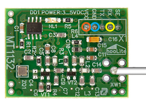
Of the entire wide spectrum of nooLite equipment, we will be interested in the MT1132 control module because it is designed to connect to Arduino and single-board computers such as the Raspberry Pi. And it works on a simple serial interface. Looking ahead a bit, I will say that I liked the module because of its simplicity, predictability and reliable operation. And I was able to appreciate these qualities after a month of fruitless struggle with the network module on the W5500 chip, which did not want to work normally.

And I especially liked the fact that (apart from power supply) the module is connected to the Arduino with just one (!) Wire (RX). The second (TX) can be omitted altogether. The module is “one-way”, that is, it is designed only for sending control signals. The plans of the Nootehnika company include the development and release of a “two-way” version of the module.

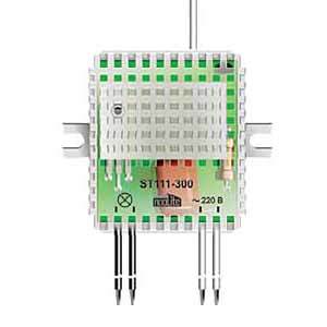
The second element we need from nooLite equipment is a power control unit, for example, SU111-300. The connection of the unit is elementary and can be seen in the illustration. Two wires are connected to a 220 volt network, and the other two to the load. The only thing I would like to pay attention to is that the modules are supplied with a jumper that blocks the dimming mode and, if you want to adjust the power, you need to cut this jumper (and remember to insulate the resulting bare wires).

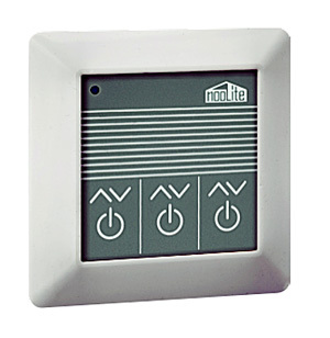
I won’t dwell on the remotes because this is a “manual” control, and we, in connection with automation, are more interested in the automatic. I can only say that the experiments were carried out with the PU311-2 remote control, made in the form of a wall switch and it showed itself in the best way, that is, it turned on and off the light clearly and without failures. What, in fact, is good equipment and different from bad - you just don’t notice good.
Work concept. Binding and Unlinking
Before you can turn electrical appliances on and off using the nooLite system, you need to “link” the control modules to the corresponding power units. This is done using the so-called procedure. “Bindings” and “untying”, described in detail in the nooLite documentation. In short, it all comes down to pressing a pair of buttons on the linked blocks and does not present any difficulties.
In the case when the MT1132 control module is used instead of the remote control, the procedure occurs in a slightly different way. Namely: since the module has no buttons, you need to programmatically generate and send a control command on the desired channel, and then press the button on the power unit, confirming the “binding” or “untying”.
Channels are “control lines” and there are 32 of them in the MT1132 module, as evidenced by the last two digits in the name. This means that with this module you can manage 32 separate groups of equipment, which is more than enough for an apartment or a small house. If you have a large house, then the modules can work in conjunction and scale to any number of channels.
Protocol Description
There is a wonderful document on the Nootehnika website that fully and fully describes the module connection and its control protocol. I will not clutter up the article with excessive technical details, anyone can read this document, I will describe only the main points.
To control the module, we need to form a control command consisting of 12 bytes. The principles for the formation of this team are described in the above document. And as you will see below, all these rules are already programmed in the control functions and we only need to use them to issue commands to the module.
Test teams
nooLite has a fairly developed command system, from which we will choose the simplest and most common ones and illustrate the system using their example.
- Snap
- Untie
- Turning on
- Off
- Power setting (dimming)
Understanding how the basic teams work, you can easily use any other.
Connecting the MT1132 module
As I already said, the MT1132 module is connected literally with one wire (except for power). The module can be powered by both a voltage of 5 volts and a voltage of 3.3 volts. Therefore, there were no problems connecting to either the 5-volt Arduino Mega or the 3.3-volt Arduino Due. The only point is that with reduced power, the range of reliable operation of the system decreases. And this must be taken into account if you want to power the module from a voltage of 3.3 volts.

The module has RX and TX pins for receiving and sending signals via the serial interface. Critical for the operation of the module is the connection of RX, for receiving control commands from the controller. Accordingly, the RX pin on the module side is connected to the TX pin (18) on the Arduino side. This pinout is valid for both Arduino Mega and Arduino Due.
Software part
Now let's figure out how to manage all this economy from sketches on Arduino. First, initialize Serial1, to which we connected the MT1132 module (this is done at the standard frequency 9600):
Serial1.begin(9600);
Now the code of the main control function:
void nooSendCommand(byte channel, byte command, byte data, byte format) {
  byte buf[12];
  for (byte i = 0; i < 12; i++) {
    buf[i] = 0;
  }
  buf[0] = 85;
  buf[1] = B01010000;
  buf[2] = command;
  buf[3] = format;
  buf[5] = channel;
  buf[6] = data;
  int checkSum = 0;
  for (byte i = 0; i < 10; i++) {
    checkSum += buf[i];
  }
  buf[10] = lowByte(checkSum);
  buf[11] = 170;
  for (byte i = 0; i < (12); i++) {
    Serial1.write(buf[i]);
  }
}
In principle, we don’t even need to know how it works, we can use it in the “black box” mode or a kind of API, with a certain interface sticking out. We just need to know how to use this interface.
As you can see, there are only four parameters - channel, command, data and format. You can read the principle by which requests to this API can be generated in the aforementioned document, but we will simplify our task even further and wrap this interface in simple nooLite device control commands.
void nooBind  (byte ch)         {nooSendCommand(ch, 15, 0, 0);}
void nooUnbind(byte ch)         {nooSendCommand(ch,  9, 0, 0);}
void nooOn    (byte ch)         {nooSendCommand(ch,  2, 0, 0);}
void nooOff   (byte ch)         {nooSendCommand(ch,  0, 0, 0);}
void nooValue (byte ch, byte v) {nooSendCommand(ch,  6, v, 1);}
Relatively complex team is only the last one, there, in addition to the channel, the power level is also set. There are also teams in the sketch that we won’t stop at now, but they are formed just as easily.
Actually ... that's it! Nowhere is easier. In the code, the control commands look like this:
nooBind(ch);
nooUnbind(ch);
nooOn(ch);
nooOff(ch);
nooValue(ch, v);
Now let's practice practicing the nooLite power module management. So, we tie the power block on the zero channel:
nooBind(0);
The LED on the power unit flashes. Press the button on the block - the LED stops flashing - the power block is attached. Instead of the zero channel, you can use any other. And you can easily generate the channel number in the sketch code according to your needs.
Turn on the lamp (if we tied the lamp on the zero channel, then the commands for it must be sent on this channel):
nooOn(0);
Set the power (brightness of the lamp):
nooValue(0, 100);
Here you need to say a little about the rules of forming a team that sets the power level. The power value does not change from 0 to 255, as one might think, but from 35 to 155. If the value is greater than 155, then the power will be maximum, if it is 0, then this will be equivalent to a shutdown command.
Here (just in case) a formula that translates “standard” values from 0 to 100 into a format understood by the nooLite module:
v = x * 1.2 + 34;
Using this formula, you can set the brightness of the lamp in the usual percentage of power. And, of course, if you need to adjust the power nonlinearly, then you can create a variable v according to any law or even just choosing fixed values. This will be discussed in the third part of the cycle, when we will adjust the heating temperature of the soldering station.
Turn off the device:
nooOff(0);
Untie:
nooUnbind(0);
The LED on the power unit flashes. We confirm the decoupling by pressing the button on the power unit. That's it, now the power unit has stopped responding to our commands and we can “snap” it again on any of the 32 channels of the nooLite MT1132 module.
Here is the full sketch.
Full sketch code
byte const PIN_TX = 18; // TX PIN (to RX noolite)
byte const PIN_RX = 19; // RX PIN (to TX noolite)
void nooSendCommand (byte channel, byte command, byte data, byte format) {
byte buf [12];
for (byte i = 0; i <12; i ++) {
buf [i] = 0;
}
buf [0] = 85;
buf [1] = B01010000;
buf [2] = command;
buf [3] = format;
buf [5] = channel;
buf [6] = data;
int checkSum = 0;
for (byte i = 0; i <10; i ++) {
checkSum + = buf [i];
}
buf [10] = lowByte (checkSum);
buf [11] = 170;
for (byte i = 0; i <(12); i ++) {
Serial1.write (buf [i]);
}
}
void nooBind (byte ch) {nooSendCommand (ch, 15, 0, 0);}
void nooUnbind (byte ch) {nooSendCommand (ch, 9, 0, 0);}
void nooOn (byte ch) {nooSendCommand (ch, 2 , 0, 0);}
void nooOff (byte ch) {nooSendCommand (ch, 0, 0, 0);}
void nooTrigger (byte ch) {nooSendCommand (ch, 4, 0, 0);}
void nooCancel (byte ch ) {nooSendCommand (ch, 10, 0, 0);}
void nooUp (byte ch) {nooSendCommand (ch, 3, 0, 0);}
void nooDown (byte ch) {nooSendCommand (ch, 1, 0, 0) ;}
void nooRevers (byte ch) {nooSendCommand (ch, 5, 0, 0);}
void nooValue (byte ch, byte v) {nooSendCommand (ch, 6, v, 1);}
void setup () {
Serial1. begin (9600);
/ * Use any desired command at a time
or write your code in loop () using these commands * /
// nooBind (0);
// nooOn (0);
// nooOff (0);
// nooValue (0, 100);
// nooUnbind (0);
}
void loop () {
}
Subtotal
As you can see, there is nothing complicated in controlling nooLite power modules using Arduino, on the contrary, the control is phenomenally simple: the module is connected with one wire, and the commands are almost a natural human language - “turn on channel 0”, “turn off channel 1”, “To set the power of 50% on channel 3” is really nowhere simpler.
Bonus for those who have read to the end
Just the other day, a new version of Arduino Mega Server was released under the number 0.14, in which all childhood diseases of the technology are overcome and which works quickly and stably. And the same version contains the integrated nooLite instrument control core and how it all works, you will learn from the next article in the series “nooLite Wireless Equipment and Smart Home (Part 2). Arduino Mega Server. "
The second , third and fourth parts of the cycle.
