The way from the layout to the serial product
Greetings to the reader!
It so happened that recently my company has been side by side with a business incubator, in which there is an abundance of young and ambitious comrades who believe that crafts made fromshit and sticks of arduino and wiring during the evening are the final product that they will sell to millions tomorrow. It is useless to argue with them, and the story of the magnitude of the gap between the layout and the serial product cannot be put in 2 sentences, so I am writing this post.
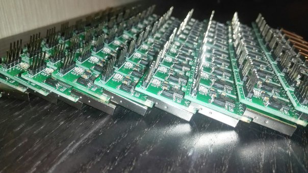
I want to tell you my experience in creating a serial device (so far <1000 pcs).
What was in the beginning
At the time of development, we can say that I did not understand anything in the manufacture of electronics, although I had experience in developing (and large) quite complex products. But all this experience ended with the development of a circuit, a board, and writing a program / guide for setting up and transferring CD to the production department. Now I had to find out all the pain and the price of mistakes.
Device
The idea of the device was simple and good. When I was mining, my farms (PC-based) often hung up, it pushed me to look for a hardware watchdog. I was surprised at the high cost of such products (at the beginning of 2014 the cheapest solution cost 800r), as well as outdated circuitry (soft usb, atmel / pic, a million components). I decided to make my bike ... Having thrown the breadboard, I did and ordered the boards.
The first version of V1.0 USBWatchDog looked like a
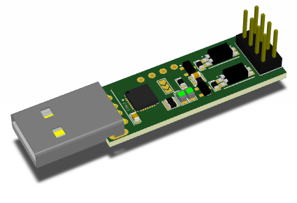
bunch of CP2102 + junior STM32F0 (at the time of development, a total of 70p retail), optocouplers, transistors, connectors, and loose powder. The fees were ordered on a common procurement (20 pieces each) undivided on seeedstudio.com. Then, for the sake of a couple of thousand savings, I was ready to split the boards with a dremel (now for no reason !!!).
Looking back at the first version, I can say that it was made extremely poorly - a bunch of CP2102 + MK, many components for reinsurance, many soldering points, errors in circuitry. The first version contained 32 components (from 2 sides) and 140 soldering points.
The main conclusions that I made after manually manufacturing 150 boards of the first version:
- boards should be either separately or in the panel (separated by jumpers). You can separate it manually 2-10, but not 150.
- select the components so that it can be soldered either with a soldering iron or with a hairdryer only. For manual soldering, QFN is evil. Again, you can put 10-20 microcircuits, but not 150.
- You cannot make circuit errors (you need to prototype and re-check everything 100 times). Soldering 150 jumpers is a pain, and the type of product is no longer a cake, you can make a mistake so that the boards are in the trash.
- 10-fold supply of components is redundant. Pick up items wisely. An extra transistor with a batch of 150 pieces is 150 transistors. And the cost of the capacitor includes 2 soldering points, which are an order of magnitude more expensive than himself.
- you definitely need a stand + software for firmware / verification. A lot of time is wasted on unprepared testing.
- connecting wires are a separate pain. You need to look for either ready-made or offices that make them.
Version V1.1 circulation of 100 boards.
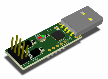
Some problems were solved:
- boards became separate.
- Corrected circuitry - assembly became easier.
- removed some "extra" components.
As a result, 21 components (from 2 sides) and 110 soldering points.
At this party, I got an installer - a wonderful girl, soldering without jambs, quickly and beautifully (Katyukha hello !!!). And I relaxed a bit, because replication is now her problem, but then she left and had to optimize and turn on her head again ... so v2.0 appeared.
Version V2.0 circulation of 150 boards.
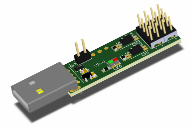
The main changes:
- he left the bundle CP2102 + MK in favor of STM32F042 in the LQFP32 copus with integrated usb. This MK is put with a soldering iron, which speeds up the installation and reduces the marriage to zero.
- Added a power system 5-> 3.3V.
- added duplication of output channels for connecting external buttons.
- reduced the range of devices - the warehouse has become more optimal.
- Found a manufacturer of wires to connect. Like a mountain from the shoulders.
A total of 22 components (from 2 sides) and 105 solder points.
The complicated connection of the device to implement the main “chip” of our device, the OFF / ON function for motherboards, which, when frozen, do not restart with the RESET button, continued to worry. It was necessary to connect an external source (for example, duty + 5V).
At this time, the dollar started to go uphill, and with it the cost of components and boards ... we had to do something and we did.
Lite and Pro circulation of 500 boards.
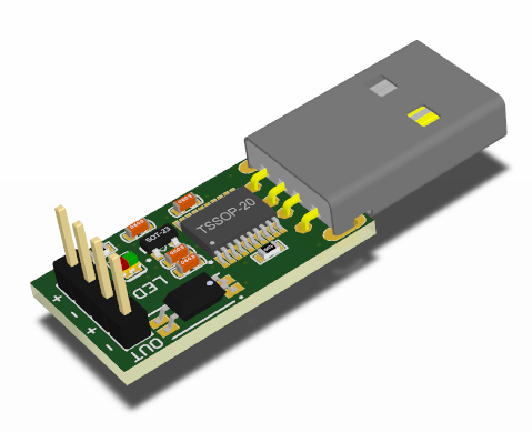
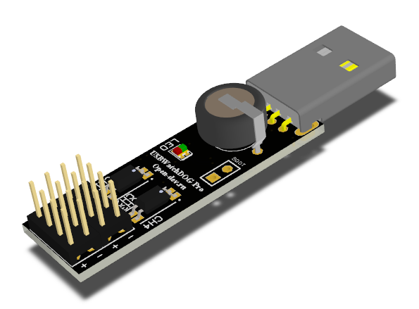
The idea was to divide devices into minimally functional and full-fledged.
Major changes:
- paneling of 10 pieces - facilitated installation.
- transition to 20 legs STM32F042 + change in circuitry.
- Lite has one-way installation.
- Pro has a backup source on board. Now there is no connection problem.
Total Lite 12 components (on the one hand) and 50 points of soldering.
Pro 23 components (from 2 sides) and 90 solder points.
If we generalize the problems that arise during large replication, we get the following list:
Here is such a big way for a small device! I would like to note that an example is described from personal experience, a fairly simple single-board and unpacked device — an ideal option for training.
It so happened that recently my company has been side by side with a business incubator, in which there is an abundance of young and ambitious comrades who believe that crafts made from

I want to tell you my experience in creating a serial device (so far <1000 pcs).
What was in the beginning
At the time of development, we can say that I did not understand anything in the manufacture of electronics, although I had experience in developing (and large) quite complex products. But all this experience ended with the development of a circuit, a board, and writing a program / guide for setting up and transferring CD to the production department. Now I had to find out all the pain and the price of mistakes.
Device
The idea of the device was simple and good. When I was mining, my farms (PC-based) often hung up, it pushed me to look for a hardware watchdog. I was surprised at the high cost of such products (at the beginning of 2014 the cheapest solution cost 800r), as well as outdated circuitry (soft usb, atmel / pic, a million components). I decided to make my bike ... Having thrown the breadboard, I did and ordered the boards.
The first version of V1.0 USBWatchDog looked like a

bunch of CP2102 + junior STM32F0 (at the time of development, a total of 70p retail), optocouplers, transistors, connectors, and loose powder. The fees were ordered on a common procurement (20 pieces each) undivided on seeedstudio.com. Then, for the sake of a couple of thousand savings, I was ready to split the boards with a dremel (now for no reason !!!).
Looking back at the first version, I can say that it was made extremely poorly - a bunch of CP2102 + MK, many components for reinsurance, many soldering points, errors in circuitry. The first version contained 32 components (from 2 sides) and 140 soldering points.
The main conclusions that I made after manually manufacturing 150 boards of the first version:
- boards should be either separately or in the panel (separated by jumpers). You can separate it manually 2-10, but not 150.
- select the components so that it can be soldered either with a soldering iron or with a hairdryer only. For manual soldering, QFN is evil. Again, you can put 10-20 microcircuits, but not 150.
- You cannot make circuit errors (you need to prototype and re-check everything 100 times). Soldering 150 jumpers is a pain, and the type of product is no longer a cake, you can make a mistake so that the boards are in the trash.
- 10-fold supply of components is redundant. Pick up items wisely. An extra transistor with a batch of 150 pieces is 150 transistors. And the cost of the capacitor includes 2 soldering points, which are an order of magnitude more expensive than himself.
- you definitely need a stand + software for firmware / verification. A lot of time is wasted on unprepared testing.
- connecting wires are a separate pain. You need to look for either ready-made or offices that make them.
Version V1.1 circulation of 100 boards.

Some problems were solved:
- boards became separate.
- Corrected circuitry - assembly became easier.
- removed some "extra" components.
As a result, 21 components (from 2 sides) and 110 soldering points.
At this party, I got an installer - a wonderful girl, soldering without jambs, quickly and beautifully (Katyukha hello !!!). And I relaxed a bit, because replication is now her problem, but then she left and had to optimize and turn on her head again ... so v2.0 appeared.
Version V2.0 circulation of 150 boards.

The main changes:
- he left the bundle CP2102 + MK in favor of STM32F042 in the LQFP32 copus with integrated usb. This MK is put with a soldering iron, which speeds up the installation and reduces the marriage to zero.
- Added a power system 5-> 3.3V.
- added duplication of output channels for connecting external buttons.
- reduced the range of devices - the warehouse has become more optimal.
- Found a manufacturer of wires to connect. Like a mountain from the shoulders.
A total of 22 components (from 2 sides) and 105 solder points.
The complicated connection of the device to implement the main “chip” of our device, the OFF / ON function for motherboards, which, when frozen, do not restart with the RESET button, continued to worry. It was necessary to connect an external source (for example, duty + 5V).
At this time, the dollar started to go uphill, and with it the cost of components and boards ... we had to do something and we did.
Lite and Pro circulation of 500 boards.


The idea was to divide devices into minimally functional and full-fledged.
Major changes:
- paneling of 10 pieces - facilitated installation.
- transition to 20 legs STM32F042 + change in circuitry.
- Lite has one-way installation.
- Pro has a backup source on board. Now there is no connection problem.
Total Lite 12 components (on the one hand) and 50 points of soldering.
Pro 23 components (from 2 sides) and 90 solder points.
If we generalize the problems that arise during large replication, we get the following list:
- Accessories Quickly get a large batch of chips for sane money is not so easy (especially for private traders). Now we use the services of Elitan, ChipDip (who would have thought), Platan (passivation) and China (if time permits, and the supplier is verified).
- Board production First ordered in China (seeedstudio.com), but at the current ruble exchange rate, Rezonit is more profitable. The easiest item.
- Installation The best way, in my opinion, is to first solder yourself (understand all the jambs and fix them), then give it to a third-party installer (now prices are around 0.7-2p per point). Then you can give it to automatic installation (for example, in the same Resonite). A rather expensive preparation (at the time of publication of Article 11000r) and a soldering point of up to 0.5r. When mounting on a machine (and for some installers) 2-sided installation costs money (for Rezonit 2000r), so installing a board with all of the elements on one side is cheaper.
- Customization / verification / packaging At the initial stage, it’s good when the developer does this - he begins to understand all the problems of his product and can fix them. According to the written instructions and on the tuning stand, this work can be done by a specially trained person.
Here is such a big way for a small device! I would like to note that an example is described from personal experience, a fairly simple single-board and unpacked device — an ideal option for training.
