Another watch or when offended by the microcontroller
At school he was fond of microelectronics, went to the radio club, assembled several simple devices. Then the university, work, marriage and very rarely remembered about his hobby.
With the advent of the Internet in my home, I found out the details about microcontrollers, looked at prices, and was eager to collect something on the AVR or STM. I re-read many forums and selections of projects on microcontrollers, but everything was something wrong, and I could not understand what was wrong. It seems like an interesting thing: a music player playing files from a memory card, or an alarm clock with a thermometer, but there’s a lot more, but the feeling that I want this didn’t arise ...
I came across several articles about watches on gas-discharge indicators of the IN series and the like, a memory came back from my childhood as in a store I looked at the numbers on the scales, and they are separate there in the form of thin wires and one of them glows.
It is decided - I will do the clock. Gas-discharge indicators work at a voltage of about 180 volts, so for coordination with the controller, the k155id1 chip is most often used - the only high-voltage chip, a binary-decimal decoder. To obtain high voltage, most projects also use a separate specialized PWM chip. And in many projects, there is also a real-time clock in the form of a separate chip or a finished assembly.
Reading the description on the store’s website for a simple Atmega8, I imagined that there was an analog-to-digital converter and pulse-width modulation, serial interfaces, etc., and they are used most often only to run the clock program, even an decoder for the indicator is set up externally. It was a shame for the microcontroller, it is so "powerful" and they do not allow it to turn around.
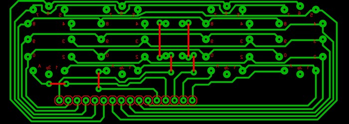
As a result, bypassing the circuit, I immediately began to draw a printed circuit board in SprintLayout and this couple was born in a couple of weeks:
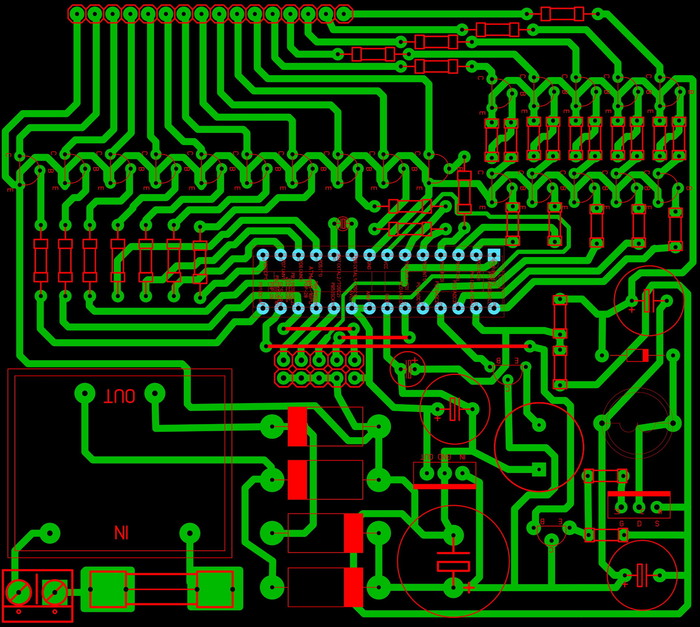
On one board everything is with power, on the other only indicators:
The atmega8 microcontroller in this project uses all three timers, one of which works asynchronously from an external clock quartz. The controller itself operates at a frequency of 8 megahertz from the internal RC chain. PWM is used to generate high voltage in a booster converter, and the voltage is controlled by an analog input, and the duty cycle is adjusted if necessary. Well, 28 legs were enough to illuminate the four IN 12 indicators, and a couple more bulbs remained.
Here's how it looks when assembled:

And it lights up:

Some of the controller functions certainly remained unused, but it’s not so annoying when there is no separate PWM and RTC nearby.
BB added part of the scheme, painted in a proteus, the couple went hard: I
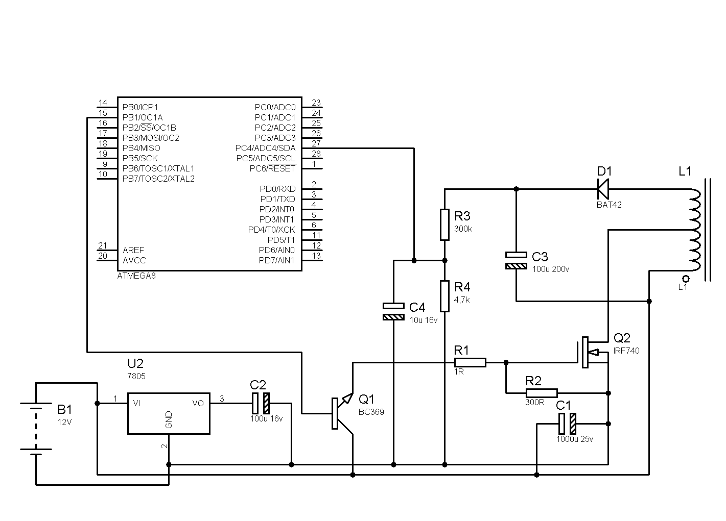
took the key scheme from here
With the advent of the Internet in my home, I found out the details about microcontrollers, looked at prices, and was eager to collect something on the AVR or STM. I re-read many forums and selections of projects on microcontrollers, but everything was something wrong, and I could not understand what was wrong. It seems like an interesting thing: a music player playing files from a memory card, or an alarm clock with a thermometer, but there’s a lot more, but the feeling that I want this didn’t arise ...
I came across several articles about watches on gas-discharge indicators of the IN series and the like, a memory came back from my childhood as in a store I looked at the numbers on the scales, and they are separate there in the form of thin wires and one of them glows.
It is decided - I will do the clock. Gas-discharge indicators work at a voltage of about 180 volts, so for coordination with the controller, the k155id1 chip is most often used - the only high-voltage chip, a binary-decimal decoder. To obtain high voltage, most projects also use a separate specialized PWM chip. And in many projects, there is also a real-time clock in the form of a separate chip or a finished assembly.
Reading the description on the store’s website for a simple Atmega8, I imagined that there was an analog-to-digital converter and pulse-width modulation, serial interfaces, etc., and they are used most often only to run the clock program, even an decoder for the indicator is set up externally. It was a shame for the microcontroller, it is so "powerful" and they do not allow it to turn around.
As a result, bypassing the circuit, I immediately began to draw a printed circuit board in SprintLayout and this couple was born in a couple of weeks:
On one board everything is with power, on the other only indicators:
The atmega8 microcontroller in this project uses all three timers, one of which works asynchronously from an external clock quartz. The controller itself operates at a frequency of 8 megahertz from the internal RC chain. PWM is used to generate high voltage in a booster converter, and the voltage is controlled by an analog input, and the duty cycle is adjusted if necessary. Well, 28 legs were enough to illuminate the four IN 12 indicators, and a couple more bulbs remained.
Here's how it looks when assembled:
And it lights up:
Some of the controller functions certainly remained unused, but it’s not so annoying when there is no separate PWM and RTC nearby.
BB added part of the scheme, painted in a proteus, the couple went hard: I
took the key scheme from here
SI project code
#define F_CPU 8000000UL
#include
#include
#include
// PWM initialization program
void init_pwm (void)
{
// Initialize the port
DDRB = 0xFF; // OC1A, OC1B, OC2 - outputs
TCCR1A = (1 <
TCCR1B = (1 <
// Setting the initial values of the counters
OCR1A = 250;
OCR1B = 215; // Disabled 0 from 200/170 to 250/215
}
volatile unsigned char second, minute, hour, h, m;
int voltage_ADC, dimm;
// Interrupt on overflow T2
ISR (TIMER2_OVF_vect)
{
if (second ++> = 59)
{
second = 0;
minute ++;
}
if (minute> 59)
{
minute = 0;
hour ++;
}
if (hour> 23)
hour = 0;
// set_time (hour, minute, second); // Display the data
}
ISR (TIMER0_OVF_vect)
{
PORTC | = (1 << PC2);
}
ISR (ADC_vect) // interrupt on completion of the ADC conversion
{
voltage_ADC = ADCW; // read the value of the AD conversion
if (voltage_ADC <260 && OCR1A <300) {OCR1A ++; OCR1B = OCR1A-dimm;}
if (voltage_ADC> 260 && OCR1A> 170) {OCR1A -; OCR1B = OCR1A-dimm;}
ADCSR | = (1 <
}
// The main program
int main (void)
{
unsigned char r;
unsigned char mode;
init_pwm (); // Initialize PWM channels
PORTD = 0x00; // Set all outputs of port D to 0, that is, turn off the entire port D
DDRD = 0xFF; // We make port D as an output, so that the output of the port has a voltage of 5V
PORTC = 0b00000000; DDRC = 0b11101111;
TIMSK & = ~ (1 << OCIE2) | (1 << TOIE2); // Disable T2 interrupts
ASSR | = (1 << AS2); // Turn on the asynchronous mode T2
TCNT2 = 0; // Reset the account register
TCCR2 | = (1 << CS22) | (0 << CS21) | (1 << CS20); // 128- (3268/128 = 256 ticks / s)
divider TIMSK | = (1 << TOIE2); // Enable T2 Overflow Interrupt
TCCR0 | = (0 <
// TIMSK | = (1 << TOIE0); //
Enable T2 overflow interrupt
// ads
ADMUX | = (1 <
// ADCSRA | = (1 <
ADCSRA | = (1 <
sei (); // Globally enable interrupts
hour = 23; // Initial time setting
minute = 13;
second = 23;
mode = 1;
while (1) // Perpetual loop
{
/ *
PORTD | = (1 << PD1); // setting bit 1
PORTD & = ~ (1 << PD1); // reset bit 1
* /
dimm = 35;
PORTC & = ~ (1 << PC2);
if (mode == 1) {m = minute; h = hour;}
if (mode == 2) {m = second; h = minute;}
if (mode == 3) {m = voltage_ADC% 100; h = voltage_ADC / 100;};
for (r = 0; r <4; r ++)
{
if (r == 1)
{
PORTC | = (1 << PC3); // tens of minutes
if (m / 10 == 0) PORTD | = (1 < <PD3); // 0
if (m / 10 == 1) PORTD | = (1 << PD2); // 1
if (m / 10 == 2) PORTB | = (1 << PB1); // 2
if (m / 10 == 3) PORTB | = (1 << PB3); // 3
if (m / 10 = = 4) PORTB | = (1 << PB4); // 4
if (m / 10 == 5) PORTD | = (1 << PD5); // 5
if (m / 10 == 6) PORTD | = (1 << PD6); // 6
if (m / 10 == 7) PORTD | = (1 << PD7); // 7
if (m / 10 == 8) PORTB | = (1 << PB0) ; // 8
if (m / 10 == 9) PORTD | = (1 << PD4); // 9
}
if (r == 0)
{
PORTC | = (1 << PC5); // minutes
if (m% 10 == 0) PORTD | = (1 << PD3); // 0
if (m% 10 == 1) PORTD | = (1 << PD2); // 1
if (m% 10 == 2) PORTB | = (1 << PB1); // 2
if (m% 10 == 3) PORTB | = (1 << PB3); // 3
if (m% 10 == 4) PORTB | = ( 1 << PB4);// 4
if (m% 10 == 5) PORTD | = (1 << PD5); // 5
if (m% 10 == 6) PORTD | = (1 << PD6); // 6
if (m% 10 == 7) PORTD | = (1 << PD7); // 7
if (m% 10 = = 8) PORTB | = (1 << PB0); // 8
if (m% 10 == 9) PORTD | = (1 << PD4); // 9
}
if (r == 2)
{
PORTD | = (1 << PD1); // tens of hours
if (h / 10 == 0) PORTD | = (1 << PD3); // 0
if (h / 10 == 1) PORTD | = (1 << PD2 ); // 1
if (h / 10 == 2) PORTB | = (1 << PB1); // 2
if (h / 10 == 3) PORTB | = (1 << PB3); // 3
if (h / 10 == 4) PORTB | = (1 << PB4); // 4
if (h / 10 == 5) PORTD | = (1 << PD5); // 5
if (h / 10 == 6) PORTD | = (1 << PD6); // 6
if (h / 10 == 7) PORTD | = (1 << PD7); // 7
if (h / 10 == 8) PORTB | = ( 1 << PB0);// 8
if (h / 10 == 9) PORTD | = (1 << PD4); // 9
}
if (r == 3)
{
PORTD | = (1 << PD0); // hours of the unit
if (h% 10 == 0) PORTD | = (1 << PD3); // 0
if (h% 10 == 1) PORTD | = ( 1 << PD2); // 1
if (h% 10 == 2) PORTB | = (1 << PB1); // 2
if (h% 10 == 3) PORTB | = (1 << PB3); // 3
if (h% 10 == 4) PORTB | = (1 << PB4); // 4
if (h% 10 == 5) PORTD | = (1 << PD5); // 5
if (h % 10 == 6) PORTD | = (1 << PD6); // 6
if (h% 10 == 7) PORTD | = (1 << PD7); // 7
if (h% 10 == 8) PORTB | = (1 << PB0); // 8
if (h% 10 == 9) PORTD | = (1 << PD4); // 9
}
_delay_ms (3);
PORTC & = ~ (1 << PC3);
PORTC & = ~ (1 << PC1);
PORTC & = ~ (1 << PC5);
PORTD & = ~ (1 << PD1);
PORTB = 0x00; PORTC = 0x00; PORTD = 0x00;
_delay_ms (1);
}
}
}
#include
#include
#include
// PWM initialization program
void init_pwm (void)
{
// Initialize the port
DDRB = 0xFF; // OC1A, OC1B, OC2 - outputs
TCCR1A = (1 <
// Setting the initial values of the counters
OCR1A = 250;
OCR1B = 215; // Disabled 0 from 200/170 to 250/215
}
volatile unsigned char second, minute, hour, h, m;
int voltage_ADC, dimm;
// Interrupt on overflow T2
ISR (TIMER2_OVF_vect)
{
if (second ++> = 59)
{
second = 0;
minute ++;
}
if (minute> 59)
{
minute = 0;
hour ++;
}
if (hour> 23)
hour = 0;
// set_time (hour, minute, second); // Display the data
}
ISR (TIMER0_OVF_vect)
{
PORTC | = (1 << PC2);
}
ISR (ADC_vect) // interrupt on completion of the ADC conversion
{
voltage_ADC = ADCW; // read the value of the AD conversion
if (voltage_ADC <260 && OCR1A <300) {OCR1A ++; OCR1B = OCR1A-dimm;}
if (voltage_ADC> 260 && OCR1A> 170) {OCR1A -; OCR1B = OCR1A-dimm;}
ADCSR | = (1 <
// The main program
int main (void)
{
unsigned char r;
unsigned char mode;
init_pwm (); // Initialize PWM channels
PORTD = 0x00; // Set all outputs of port D to 0, that is, turn off the entire port D
DDRD = 0xFF; // We make port D as an output, so that the output of the port has a voltage of 5V
PORTC = 0b00000000; DDRC = 0b11101111;
TIMSK & = ~ (1 << OCIE2) | (1 << TOIE2); // Disable T2 interrupts
ASSR | = (1 << AS2); // Turn on the asynchronous mode T2
TCNT2 = 0; // Reset the account register
TCCR2 | = (1 << CS22) | (0 << CS21) | (1 << CS20); // 128- (3268/128 = 256 ticks / s)
divider TIMSK | = (1 << TOIE2); // Enable T2 Overflow Interrupt
TCCR0 | = (0 <
// ads
ADMUX | = (1 <
hour = 23; // Initial time setting
minute = 13;
second = 23;
mode = 1;
while (1) // Perpetual loop
{
/ *
PORTD | = (1 << PD1); // setting bit 1
PORTD & = ~ (1 << PD1); // reset bit 1
* /
dimm = 35;
PORTC & = ~ (1 << PC2);
if (mode == 1) {m = minute; h = hour;}
if (mode == 2) {m = second; h = minute;}
if (mode == 3) {m = voltage_ADC% 100; h = voltage_ADC / 100;};
for (r = 0; r <4; r ++)
{
if (r == 1)
{
PORTC | = (1 << PC3); // tens of minutes
if (m / 10 == 0) PORTD | = (1 < <PD3); // 0
if (m / 10 == 1) PORTD | = (1 << PD2); // 1
if (m / 10 == 2) PORTB | = (1 << PB1); // 2
if (m / 10 == 3) PORTB | = (1 << PB3); // 3
if (m / 10 = = 4) PORTB | = (1 << PB4); // 4
if (m / 10 == 5) PORTD | = (1 << PD5); // 5
if (m / 10 == 6) PORTD | = (1 << PD6); // 6
if (m / 10 == 7) PORTD | = (1 << PD7); // 7
if (m / 10 == 8) PORTB | = (1 << PB0) ; // 8
if (m / 10 == 9) PORTD | = (1 << PD4); // 9
}
if (r == 0)
{
PORTC | = (1 << PC5); // minutes
if (m% 10 == 0) PORTD | = (1 << PD3); // 0
if (m% 10 == 1) PORTD | = (1 << PD2); // 1
if (m% 10 == 2) PORTB | = (1 << PB1); // 2
if (m% 10 == 3) PORTB | = (1 << PB3); // 3
if (m% 10 == 4) PORTB | = ( 1 << PB4);// 4
if (m% 10 == 5) PORTD | = (1 << PD5); // 5
if (m% 10 == 6) PORTD | = (1 << PD6); // 6
if (m% 10 == 7) PORTD | = (1 << PD7); // 7
if (m% 10 = = 8) PORTB | = (1 << PB0); // 8
if (m% 10 == 9) PORTD | = (1 << PD4); // 9
}
if (r == 2)
{
PORTD | = (1 << PD1); // tens of hours
if (h / 10 == 0) PORTD | = (1 << PD3); // 0
if (h / 10 == 1) PORTD | = (1 << PD2 ); // 1
if (h / 10 == 2) PORTB | = (1 << PB1); // 2
if (h / 10 == 3) PORTB | = (1 << PB3); // 3
if (h / 10 == 4) PORTB | = (1 << PB4); // 4
if (h / 10 == 5) PORTD | = (1 << PD5); // 5
if (h / 10 == 6) PORTD | = (1 << PD6); // 6
if (h / 10 == 7) PORTD | = (1 << PD7); // 7
if (h / 10 == 8) PORTB | = ( 1 << PB0);// 8
if (h / 10 == 9) PORTD | = (1 << PD4); // 9
}
if (r == 3)
{
PORTD | = (1 << PD0); // hours of the unit
if (h% 10 == 0) PORTD | = (1 << PD3); // 0
if (h% 10 == 1) PORTD | = ( 1 << PD2); // 1
if (h% 10 == 2) PORTB | = (1 << PB1); // 2
if (h% 10 == 3) PORTB | = (1 << PB3); // 3
if (h% 10 == 4) PORTB | = (1 << PB4); // 4
if (h% 10 == 5) PORTD | = (1 << PD5); // 5
if (h % 10 == 6) PORTD | = (1 << PD6); // 6
if (h% 10 == 7) PORTD | = (1 << PD7); // 7
if (h% 10 == 8) PORTB | = (1 << PB0); // 8
if (h% 10 == 9) PORTD | = (1 << PD4); // 9
}
_delay_ms (3);
PORTC & = ~ (1 << PC3);
PORTC & = ~ (1 << PC1);
PORTC & = ~ (1 << PC5);
PORTD & = ~ (1 << PD1);
PORTB = 0x00; PORTC = 0x00; PORTD = 0x00;
_delay_ms (1);
}
}
}