LED Strip Control Controller LED-C-01
Currently, multi-color LED strip has become widespread and is widely popular in many areas of human activity. So, in particular, RGB- tapes can be found in ordinary apartments and country houses. Often they are used as decoration for shops or shopping centers. In recent years, LED multi-color tapes have become a decoration for cars and are used in tuning.
In order to control such a tape, a special controller is needed. We have developed an electronic device designed to control a multi-color LED strip - the LED-C-01 controller.
Using our LED-C-01 controller, you can control LED strips from any device on which you can start an Internet browser, whether it is a desktop computer, laptop, tablet or smartphone. The controller allows you to quickly and easily change the color of the tape, turn the device on and off, and also view the current status of the tape (on / off). All this makes it possible to control the tape at a remote distance.
The entire elemental base is built on time-tested components and does not contain expensive parts, which allowed to reduce the cost of the controller and increase its reliability.
The controller has one input for power. Supported voltage is 12 V and 24 V (depending on the supply voltage of the LED strip itself). This allows you to support a huge number of LED strips from different manufacturers.
In addition, on the front panel there are two connectors for connecting the RGB-tapes themselves. Each connector has three channels (for controlling red, green and blue colors of the tape). Each channel is able to withstand a load of up to 30 A (according to the datasheet, transistors can withstand current up to 130 A, but for this you need to change the tracks on the board and install powerful radiators and cooling).
Also on the front panel of the device there is an RJ-45 connector for connecting the controller to the smart home LAN.
Initially, we planned to use in each of our devices the Ethernet module we developed for managing devices via HTTP requests. Therefore, in this controller, we also decided to use this module.
After we developed the basic requirements for our controller under development, we made the first prototype of the device using the LUT method. We checked its work on several scraps of LED strips (there were no long strips at hand) and, making sure that everything worked as we wanted, we ordered the first batch of boards at the factory:
By the time the boards arrived from the factory, it was finally purchased whole tape 5 meters long and we started assembling devices.
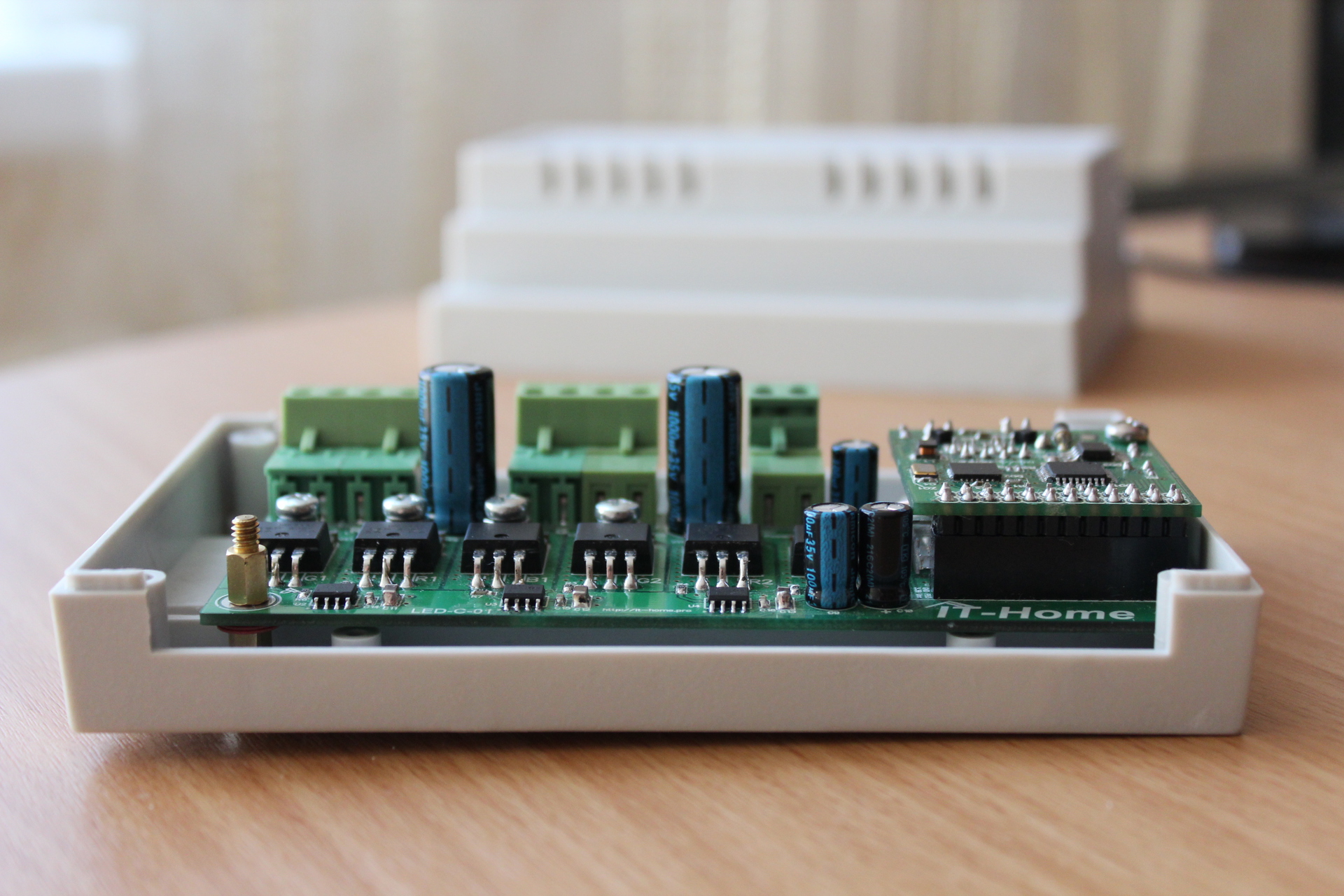
Main board, without installed Ethernet-module:
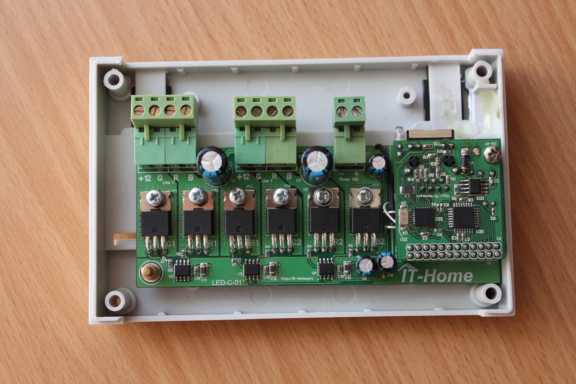
With installed Ethernet-module:
View of the board from the side of the connectors:
After assembly, we connected a 5 meter LED RGB strip to the device and started testing.
We were disappointed. No, the tape, of course, caught fire and was controlled. But the transfer of the command to turn on the tape in white led to the following (clickable): We chose a frequency too high for the PWM (25 kHz) and the tape glowed unevenly. After a series of experiments with different tapes, we stopped at a frequency of 750 Hz and everything fell intoplace :)
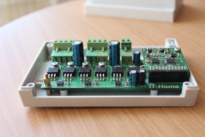
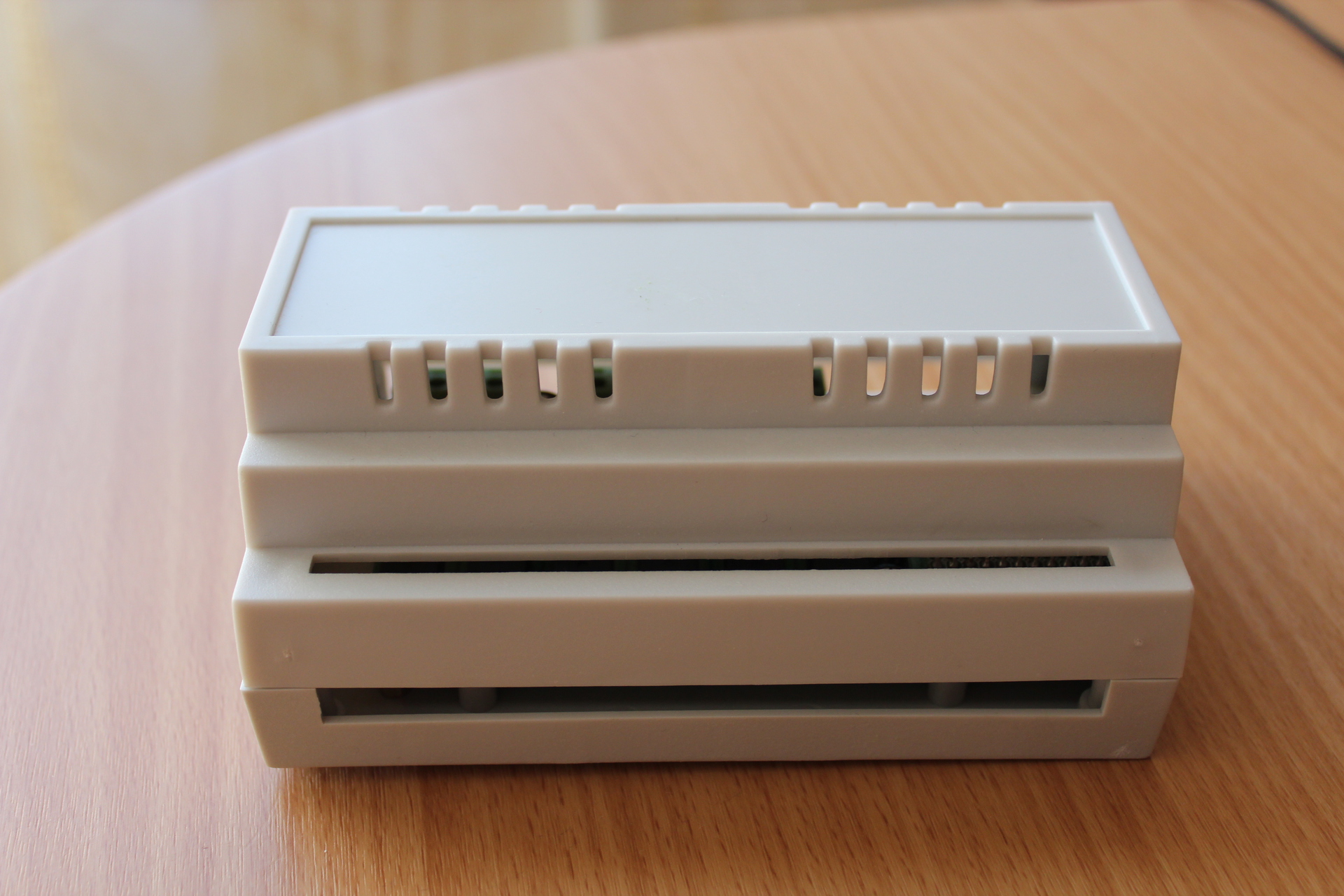
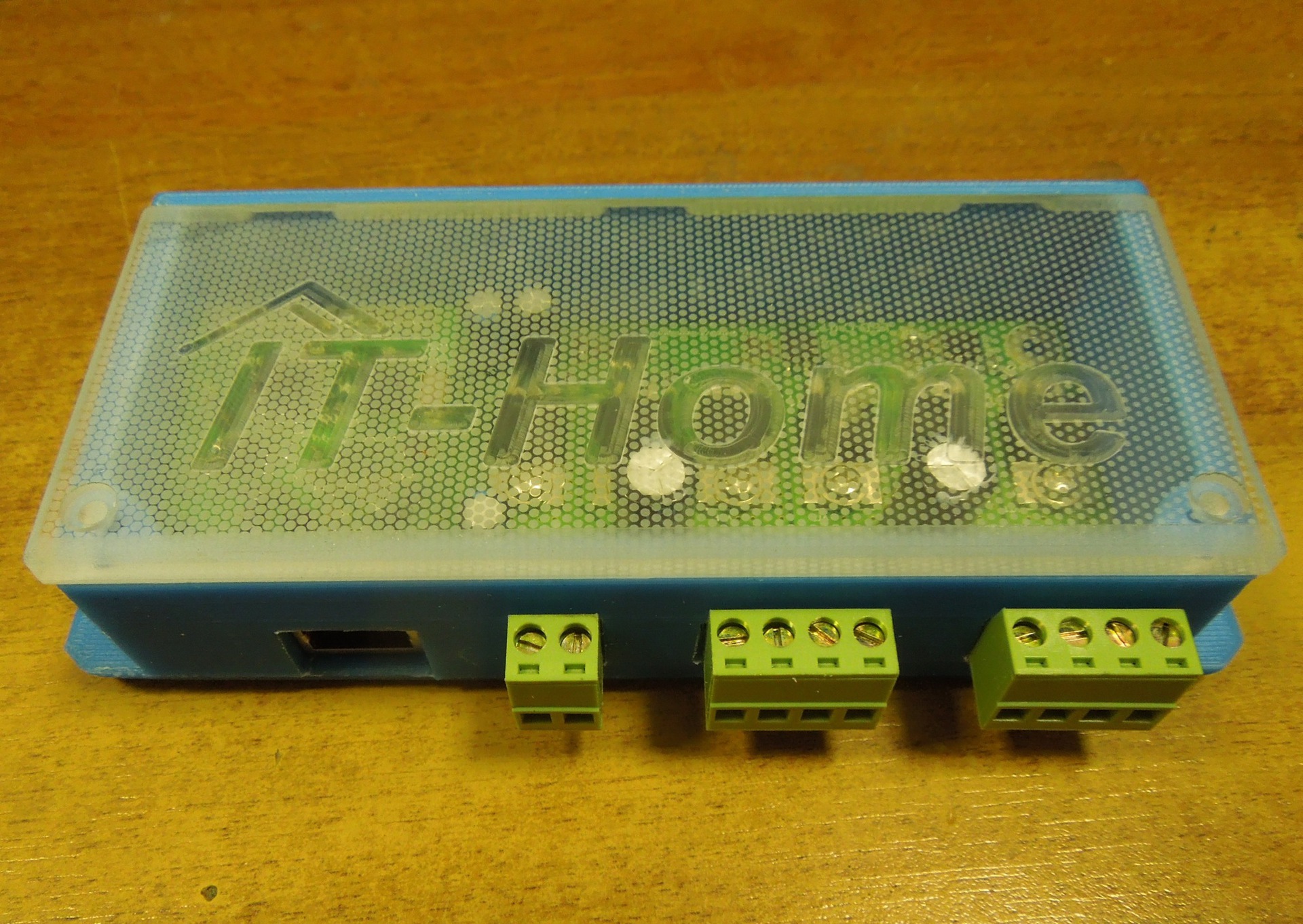
The first assembled copy of LED-C-01, before being installed in my friend’s apartment, was placed in a ready-made plastic case purchased in a nearby store (on KDPV This first instance, and below the photo is clickable):

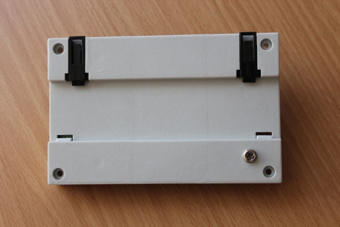
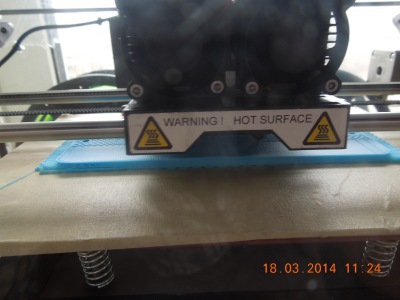
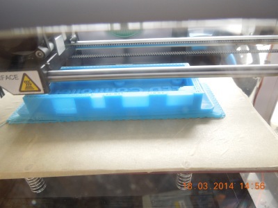
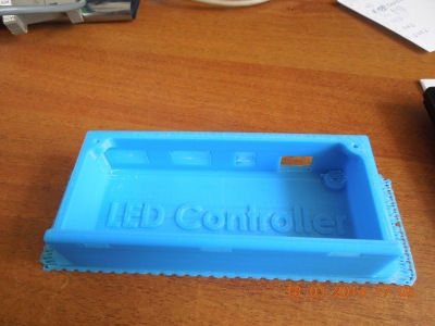
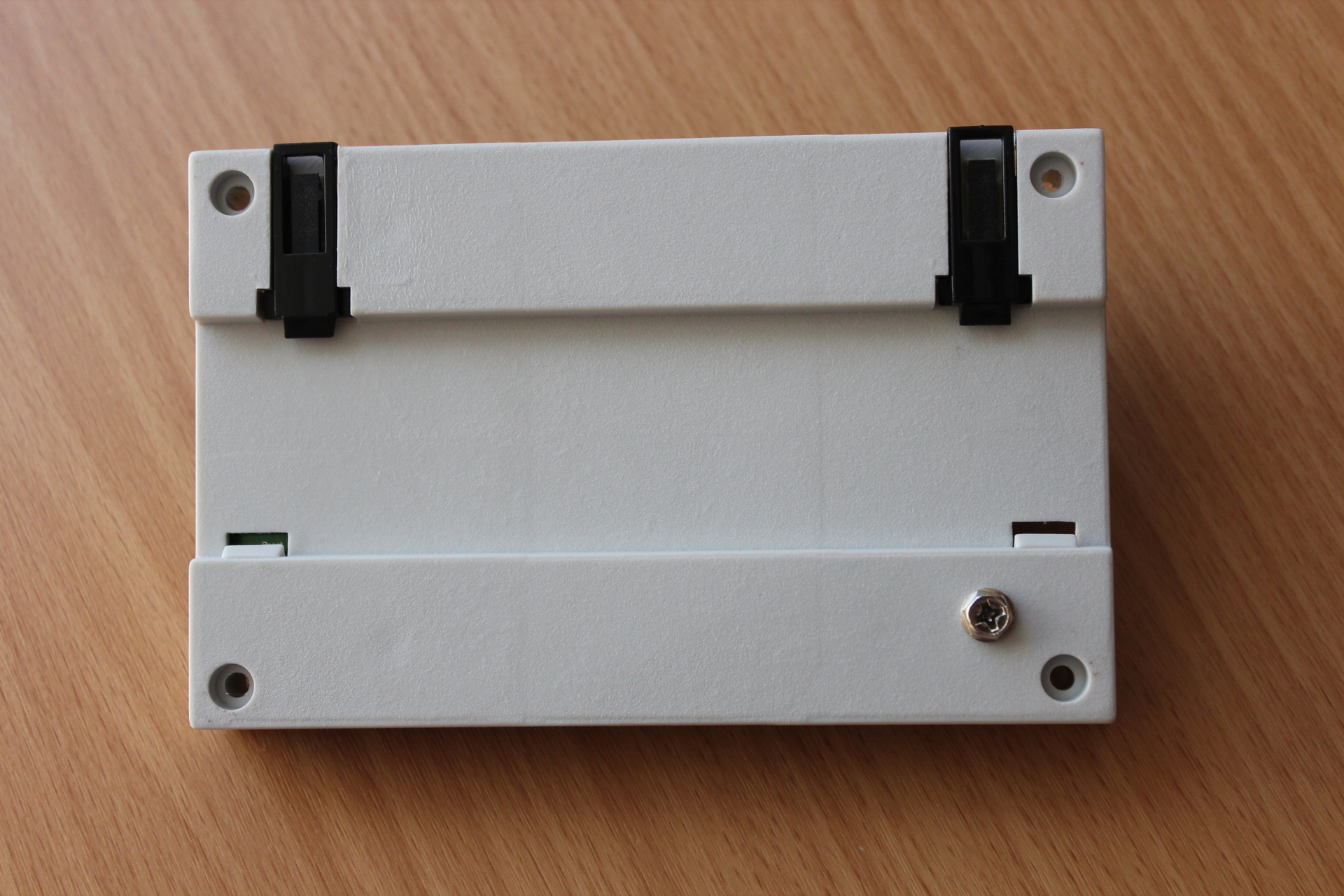
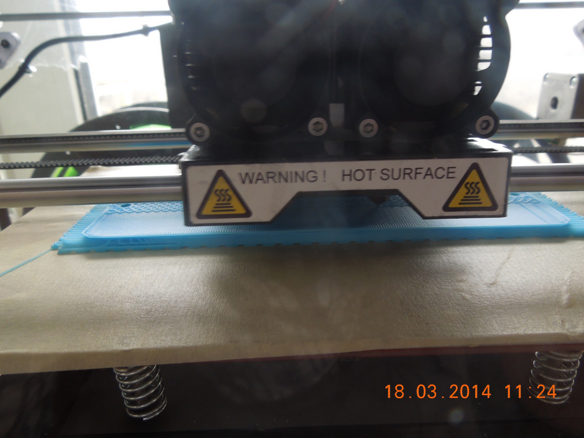
Due to the fact that the case was selected in a very short time, I had to use hot glue: Reverse side (from the side of the DIN rail mounting): Device assembly: After I was tormented with this case during its assembly, and even installation time of the device in a friend’s apartment (to connect the device, you need to completely disassemble the case, then assemble it), it was decided to make the case on a 3D printer. To do this, we developed a housing model: And printed the housing on a 3D printer (clickable): As a result, the second copy turned out like this (clickable):


The device is controlled using the HTTP protocol (Get method). The controller connects to the local network of the "smart home" (via the RJ-45 connector) and can be controlled from any computer device also connected to this network.
Currently, SSL is not supported, and therefore a special secret word is provided with which you can restrict the control of the controller.
Management is as follows. When accessing the controller from a browser from any computer device, a web page opens. On it, you can set the initial parameters: set the IP address of the device and the secret word, as well as set the color of the LED strip, and turn the tape on and off.
All necessary request arguments are passed in its parameters.
For example, turning on the white color of a tape connected to the second channel of the controller is performed by the following request:
Here the parameters red2, green2 and blue2, as you might guess, are responsible for the color.
The smo2 parameter set to “0” means that the color switch will be sharp, not smooth.
If you specify smo2 = 8, then the tape state will switch over during eight “conditional time intervals” :)
Each “conditional time interval” is 5 seconds.
To manipulate the first channel, it is necessary to transmit the same requests, only instead of “2” in all parameter names there will be “1”. For example,
As a result of this request, the tape on the first channel will switch to red during five “conditional time intervals” (that is, 25 seconds) :)
Thank you for your attention!
Other articles about our devices for:
Teacher's Day!
UPD : Corrected the current information in the article.
In order to control such a tape, a special controller is needed. We have developed an electronic device designed to control a multi-color LED strip - the LED-C-01 controller.
Using our LED-C-01 controller, you can control LED strips from any device on which you can start an Internet browser, whether it is a desktop computer, laptop, tablet or smartphone. The controller allows you to quickly and easily change the color of the tape, turn the device on and off, and also view the current status of the tape (on / off). All this makes it possible to control the tape at a remote distance.
Key device features
The entire elemental base is built on time-tested components and does not contain expensive parts, which allowed to reduce the cost of the controller and increase its reliability.
Iron
- ATmega 328 processor;
- LED control: PWM method;
- power switches based on field effect transistors IRL3716
- 2 RGB channels for connecting LED strips;
- Ethernet interface for connecting to a network;
- Ethernet controller: ENC28J60;
- supply voltage - 12 V / 24 V, constant.
Firmware
- built-in web server for management and configuration;
- http request management (GET method);
- initial configuration of the LED-C-01 controller is carried out using the web interface.
physical characteristics
- plastic case;
- overall dimensions: 153x58x37 (mm);
- weight: 0.25 kg;
- working temperature range: -25 ° C to 65 ° C.
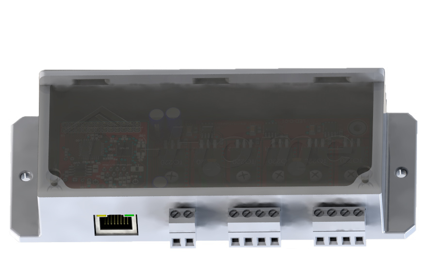
The controller has one input for power. Supported voltage is 12 V and 24 V (depending on the supply voltage of the LED strip itself). This allows you to support a huge number of LED strips from different manufacturers.
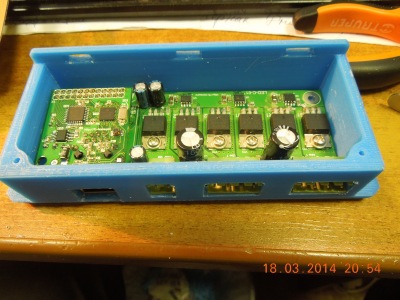
In addition, on the front panel there are two connectors for connecting the RGB-tapes themselves. Each connector has three channels (for controlling red, green and blue colors of the tape). Each channel is able to withstand a load of up to 30 A (according to the datasheet, transistors can withstand current up to 130 A, but for this you need to change the tracks on the board and install powerful radiators and cooling).
Also on the front panel of the device there is an RJ-45 connector for connecting the controller to the smart home LAN.
Initially, we planned to use in each of our devices the Ethernet module we developed for managing devices via HTTP requests. Therefore, in this controller, we also decided to use this module.
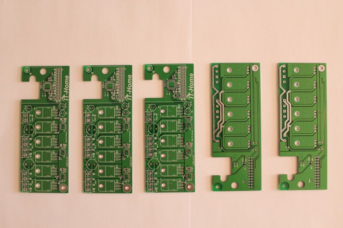
After we developed the basic requirements for our controller under development, we made the first prototype of the device using the LUT method. We checked its work on several scraps of LED strips (there were no long strips at hand) and, making sure that everything worked as we wanted, we ordered the first batch of boards at the factory:
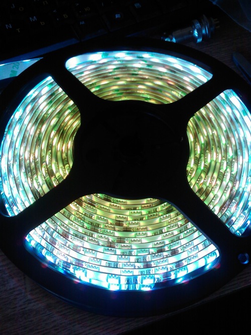
By the time the boards arrived from the factory, it was finally purchased whole tape 5 meters long and we started assembling devices.
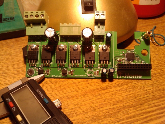
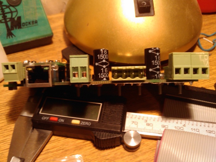
Main board, without installed Ethernet-module:
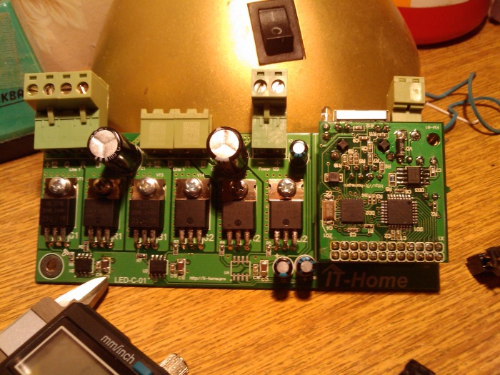
With installed Ethernet-module:
View of the board from the side of the connectors:
After assembly, we connected a 5 meter LED RGB strip to the device and started testing.
We were disappointed. No, the tape, of course, caught fire and was controlled. But the transfer of the command to turn on the tape in white led to the following (clickable): We chose a frequency too high for the PWM (25 kHz) and the tape glowed unevenly. After a series of experiments with different tapes, we stopped at a frequency of 750 Hz and everything fell into

Due to the fact that the case was selected in a very short time, I had to use hot glue: Reverse side (from the side of the DIN rail mounting): Device assembly: After I was tormented with this case during its assembly, and even installation time of the device in a friend’s apartment (to connect the device, you need to completely disassemble the case, then assemble it), it was decided to make the case on a 3D printer. To do this, we developed a housing model: And printed the housing on a 3D printer (clickable): As a result, the second copy turned out like this (clickable):


How is the controller controlled?
The device is controlled using the HTTP protocol (Get method). The controller connects to the local network of the "smart home" (via the RJ-45 connector) and can be controlled from any computer device also connected to this network.
Currently, SSL is not supported, and therefore a special secret word is provided with which you can restrict the control of the controller.
Management is as follows. When accessing the controller from a browser from any computer device, a web page opens. On it, you can set the initial parameters: set the IP address of the device and the secret word, as well as set the color of the LED strip, and turn the tape on and off.
All necessary request arguments are passed in its parameters.
For example, turning on the white color of a tape connected to the second channel of the controller is performed by the following request:
http://192.168.2.18/secretword/?frm=2&red2=255&green2=255&blue2=255&smo2=0
Here the parameters red2, green2 and blue2, as you might guess, are responsible for the color.
The smo2 parameter set to “0” means that the color switch will be sharp, not smooth.
If you specify smo2 = 8, then the tape state will switch over during eight “conditional time intervals” :)
Each “conditional time interval” is 5 seconds.
To manipulate the first channel, it is necessary to transmit the same requests, only instead of “2” in all parameter names there will be “1”. For example,
http://192.168.2.18/secretword/?frm=1&red1=255&green1=0&blue1=0&smo1=5
As a result of this request, the tape on the first channel will switch to red during five “conditional time intervals” (that is, 25 seconds) :)
Thank you for your attention!
Other articles about our devices for:
- Ethernet connections .
- Lighting control .
- Multiroom controller .
- Collection of information from motion sensors.
- Electric floor heating control.
- Lighting control stairs.
Teacher's Day!
UPD : Corrected the current information in the article.