Individual mock-ups for a radio-electronics club based on ... yes, yes, again Arduino
I am a very lazy second-year student at the Faculty of Physics, in addition, I am engaged in a circle of radio electronics. Sometimes I almost live where I learn the basics and wander in the wilds of everything interesting in the field of electronics. It was not my old idea and it was implemented in the summer. When, as you know, there are no classes in educational institutions. But this does not mean a lack of activity there. In a warm period of time, the movement takes place in a relaxed atmosphere - with a seagull, a bun and pleasant music, which even contributes ... in short, things are going on.
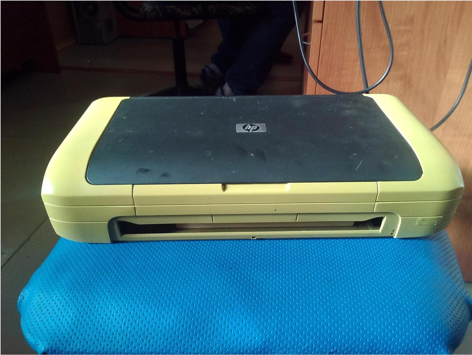
Once, the teacher shared the idea of making individual mockups for the guys, and then the opportunity turned up. Available were portable HP DeskJet 460 printers. Somewhere they wrote off a couple of dozen. Well, how not to use it?

We immediately determined with iron, because The target audience has different experience and age. From 12 to 20 years. This does not bother the guys, we all help each other. The team is responsive. In the bins, especially for these purposes, in the circle there were Arduino UNO R3 with 328 mega. You can read the characteristics on the Internet yourself.
Attention! There are a lot of images in the publication!
With introductions we round off. With shouts of "madness!" start breaking!
Pulling out the entire filling, taking what is needed (bolts or something else ...) and leaving the case with the covers, we get such a skeleton:

Red dotted line - we cut off the excess. Hacksaw, where they nibbled with wire cutters - not the point. Two yellow circles-oval-ellipse (whoever wants to) indicate rectangular holes for the power and usb connectors of the board itself.
Having scoffed at the skeleton, we get:

After - cleaning, drying and painting. Painting turned out to be a rather interesting process and took place in a nearby car workshop, where there is a rather competent cabinet with ventilation made by the hands of a car mechanist, allocated for these purposes. At first, the mentor painted, but we also really wanted to try. I held the airbrush (spray gun) for the first time, and I found the subtleties of the process with a guy of 14 years old. Everything took place in an informal setting and nobody scolded the jambs (and I don’t remember that), but only pointed to them. At the end of a new process for us, it turned out somehow like this:
Next, the “brains” were assembled and assembled. In the process, we gained skills in handling a jigsaw. Sawed board - the basis on which solderless prototyping boards and arduinka are mounted. On mock-ups (solderless) they decided how to dispose and how much. With experience, it came out that two are better than one when you need to breed different chains or something else. They glued them to double-sided tape. The "brains" were put on the cogs, mounted (super glue) in the holes of the nut board. There were several little things with a skewed board (arduino) in a fixed state. Jokes helped to fix them, the rope - oh, savvy - and patience. For a long time I customized the holes in the case for the connectors (usb and power on the board). We didn’t want to get up as it should, but we won. They did not begin to cover the piece of wood, because we do not hold any aggressive reagents nearby.


As you can see from the image above, a tray from under the cottage cheese (by the way, delicious, ah-ah) is inserted in the left case, for storing jumpers or other small gizmos. On the right we left a place for a USB cable and relatively large things such as a screen and ... well, what the soul desires.
The following image has reference materials on the inside of the lid. It contains commands for the Arduino environment, such as:
"digitalWrite ();"
"delay ();" and others.
In order not to run far and not to climb. In the end, just too lazy to go to the browser, as often happens.

Also, the guys made such shields for training beginners and more. I was not involved in shields - I closed debts at the university (I’m a lazy person, I say), I came and saw the finished ones.
Development (scheme) was carried out by one of the students as a project on the instructions of the teacher, and etching, installation, etc. - all together. By the way, the manufacture of printed circuit boards is done by the guys themselves, using photoresist. The stanochka (pressure table-lamp) for this is also manually made by the teacher.

The yellow and red LEDs are divided into groups of analog and digital pins, which allows you to teach the basics of working with the main commands and functions of the Arduino environment (cycles, conditions, digital input-output). Two buttons also contribute to this, with which you can implement, for example, enumerating the effects of "running lights", or accelerating / slowing down their movement. The RGB LED is connected to the PWM pins and is primarily used to familiarize yourself with the analog output command. The resistors on the shield are selected so that the intensity of the glow of the various LEDs is approximately the same and does not bother during prolonged use.

Right at our fingertips there is a magic piece of paper where all used pins and their purpose are registered. D and A are digital and analog I / O, respectively, although analog are used as digital.
The models are based on the Chinese counterparts of the Arduino UNO R3, which means that the virtual COM port is implemented on the CH340G microchip, which required additional driver downloads from the Chinese site. Also pleased with the presence of a standard bootloader-bootloader, which eliminated the fuss with the programmer (collected on the site the esteemed DIHALT-a), which I have not yet mastered to the end. They got used to the programming environment pretty quickly too (in the future, we might try something else). I especially liked the presence of libraries, one of which I tried by connecting, for the first time in my life, a display device. The following photo is not for you to observe the connection of the screen (this is not so difficult), but for contemplating the final state of the layout, which is in combat technical testing!

In total ten pieces turned out:

There was an interesting moment. The practicality of the layout, at first glance, is great - disconnected, closed and put on the shelf. But they discussed the option of losing the elasticity of the clamps in the breadboard (white), if you do not remove parts, displays, etc. from them, when you leave for a relatively long period. Well, here we wait - we'll see.
Adults and children use the model, and there are no complaints about the difficulty in sticking fingers! Enough space for everyone. As for my personal opinion about the comfort of using such gizmos - it's very cool. There is no mess on the table, or rather it is, but not as crazy as usual! Tips under the nose.
There is where to push the multimeter, although there is a separate box for them. Also, the whole structure does not take up much space and it’s just nice to realize that you are sitting and working on a piece of iron made by yourself.
Introduction
Once, the teacher shared the idea of making individual mockups for the guys, and then the opportunity turned up. Available were portable HP DeskJet 460 printers. Somewhere they wrote off a couple of dozen. Well, how not to use it?
We immediately determined with iron, because The target audience has different experience and age. From 12 to 20 years. This does not bother the guys, we all help each other. The team is responsive. In the bins, especially for these purposes, in the circle there were Arduino UNO R3 with 328 mega. You can read the characteristics on the Internet yourself.
Attention! There are a lot of images in the publication!
With introductions we round off. With shouts of "madness!" start breaking!
Gutting and assembly
Pulling out the entire filling, taking what is needed (bolts or something else ...) and leaving the case with the covers, we get such a skeleton:
Red dotted line - we cut off the excess. Hacksaw, where they nibbled with wire cutters - not the point. Two yellow circles-oval-ellipse (whoever wants to) indicate rectangular holes for the power and usb connectors of the board itself.
Having scoffed at the skeleton, we get:
After - cleaning, drying and painting. Painting turned out to be a rather interesting process and took place in a nearby car workshop, where there is a rather competent cabinet with ventilation made by the hands of a car mechanist, allocated for these purposes. At first, the mentor painted, but we also really wanted to try. I held the airbrush (spray gun) for the first time, and I found the subtleties of the process with a guy of 14 years old. Everything took place in an informal setting and nobody scolded the jambs (and I don’t remember that), but only pointed to them. At the end of a new process for us, it turned out somehow like this:
Next, the “brains” were assembled and assembled. In the process, we gained skills in handling a jigsaw. Sawed board - the basis on which solderless prototyping boards and arduinka are mounted. On mock-ups (solderless) they decided how to dispose and how much. With experience, it came out that two are better than one when you need to breed different chains or something else. They glued them to double-sided tape. The "brains" were put on the cogs, mounted (super glue) in the holes of the nut board. There were several little things with a skewed board (arduino) in a fixed state. Jokes helped to fix them, the rope - oh, savvy - and patience. For a long time I customized the holes in the case for the connectors (usb and power on the board). We didn’t want to get up as it should, but we won. They did not begin to cover the piece of wood, because we do not hold any aggressive reagents nearby.
Party of ready-made layouts
As you can see from the image above, a tray from under the cottage cheese (by the way, delicious, ah-ah) is inserted in the left case, for storing jumpers or other small gizmos. On the right we left a place for a USB cable and relatively large things such as a screen and ... well, what the soul desires.
The following image has reference materials on the inside of the lid. It contains commands for the Arduino environment, such as:
"digitalWrite ();"
"delay ();" and others.
In order not to run far and not to climb. In the end, just too lazy to go to the browser, as often happens.
Sample pen, or iron
Also, the guys made such shields for training beginners and more. I was not involved in shields - I closed debts at the university (I’m a lazy person, I say), I came and saw the finished ones.
Development (scheme) was carried out by one of the students as a project on the instructions of the teacher, and etching, installation, etc. - all together. By the way, the manufacture of printed circuit boards is done by the guys themselves, using photoresist. The stanochka (pressure table-lamp) for this is also manually made by the teacher.
The yellow and red LEDs are divided into groups of analog and digital pins, which allows you to teach the basics of working with the main commands and functions of the Arduino environment (cycles, conditions, digital input-output). Two buttons also contribute to this, with which you can implement, for example, enumerating the effects of "running lights", or accelerating / slowing down their movement. The RGB LED is connected to the PWM pins and is primarily used to familiarize yourself with the analog output command. The resistors on the shield are selected so that the intensity of the glow of the various LEDs is approximately the same and does not bother during prolonged use.
Right at our fingertips there is a magic piece of paper where all used pins and their purpose are registered. D and A are digital and analog I / O, respectively, although analog are used as digital.
The models are based on the Chinese counterparts of the Arduino UNO R3, which means that the virtual COM port is implemented on the CH340G microchip, which required additional driver downloads from the Chinese site. Also pleased with the presence of a standard bootloader-bootloader, which eliminated the fuss with the programmer (collected on the site the esteemed DIHALT-a), which I have not yet mastered to the end. They got used to the programming environment pretty quickly too (in the future, we might try something else). I especially liked the presence of libraries, one of which I tried by connecting, for the first time in my life, a display device. The following photo is not for you to observe the connection of the screen (this is not so difficult), but for contemplating the final state of the layout, which is in combat technical testing!
In total ten pieces turned out:
Total
There was an interesting moment. The practicality of the layout, at first glance, is great - disconnected, closed and put on the shelf. But they discussed the option of losing the elasticity of the clamps in the breadboard (white), if you do not remove parts, displays, etc. from them, when you leave for a relatively long period. Well, here we wait - we'll see.
Adults and children use the model, and there are no complaints about the difficulty in sticking fingers! Enough space for everyone. As for my personal opinion about the comfort of using such gizmos - it's very cool. There is no mess on the table, or rather it is, but not as crazy as usual! Tips under the nose.
There is where to push the multimeter, although there is a separate box for them. Also, the whole structure does not take up much space and it’s just nice to realize that you are sitting and working on a piece of iron made by yourself.