Large-scale 3D printing: FUSE Pavilion
- Transfer
Different people have a different understanding of the word "scale." For designers and entrepreneurs, scale is the number of parts in production. For architects and designers, scale is the size of development, and how it relates to the people who inhabit or use it.
Selective laser sintering (SLS) technology offers the potential for large-scale 3D printing in both senses. Designers can pack parts tightly to produce a lot of everything at the same time, and each of these parts can be unique and meet specific needs, since SLP eliminates the need for machining.
To test the capabilities of the technology, we decided to print a large pavilion, which will serve as a meeting place at the 2017 FUSE conference. We used the Fuse 1 printer to create more than a hundred structural modules, which we then assembled for four days to build a structure covering an area of 14 square meters. m
If you can create any shape, what will you do?
All three-dimensional forms can be abstractly represented as dots, edges and faces - this is how the printed object is represented in the STL file. Usually we do development with a sufficiently large resolution, so that when printing the part of the right size, the grid disappears. But what if we use mesh structure in our favor, automatically translating STL into a structured system?
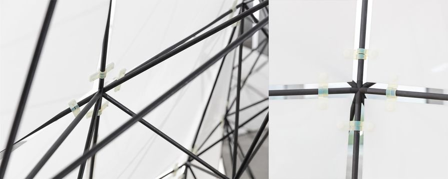
Each point of intersection of the faces turns into a connecting node, each face becomes a spacer, and each face becomes a panel. This gives us the freedom to create almost any form on a scale exceeding the human.
Creating large objects is interesting, and we started the development by simply expanding popular objects. We immediately thought about increasing the Stanford rabbitand the Formlabs logo. But then we stopped at creating something more suited to a specific purpose, so we started developing a pavilion for FUSE 2017.
Structural design of the pavilion
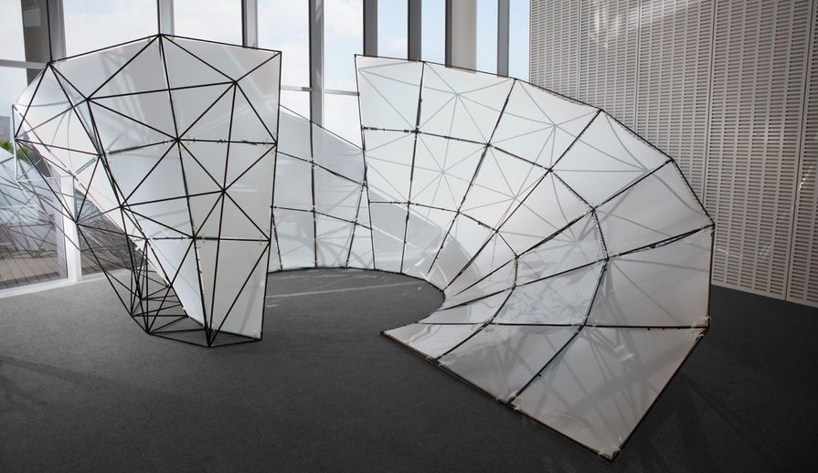
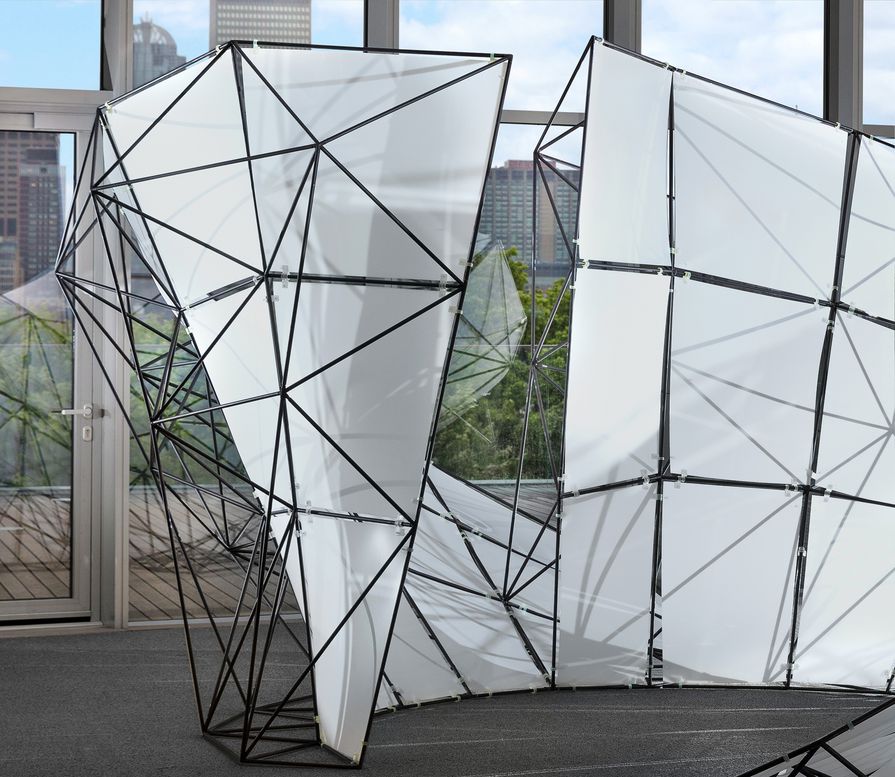
We settled on a project that developed from the equation for the Mobius strip , rotated so that a closed pavilion was formed, surrounded by three wide canvases. The canvases become stiff and provide structural support while adding a spatial frame to the back .
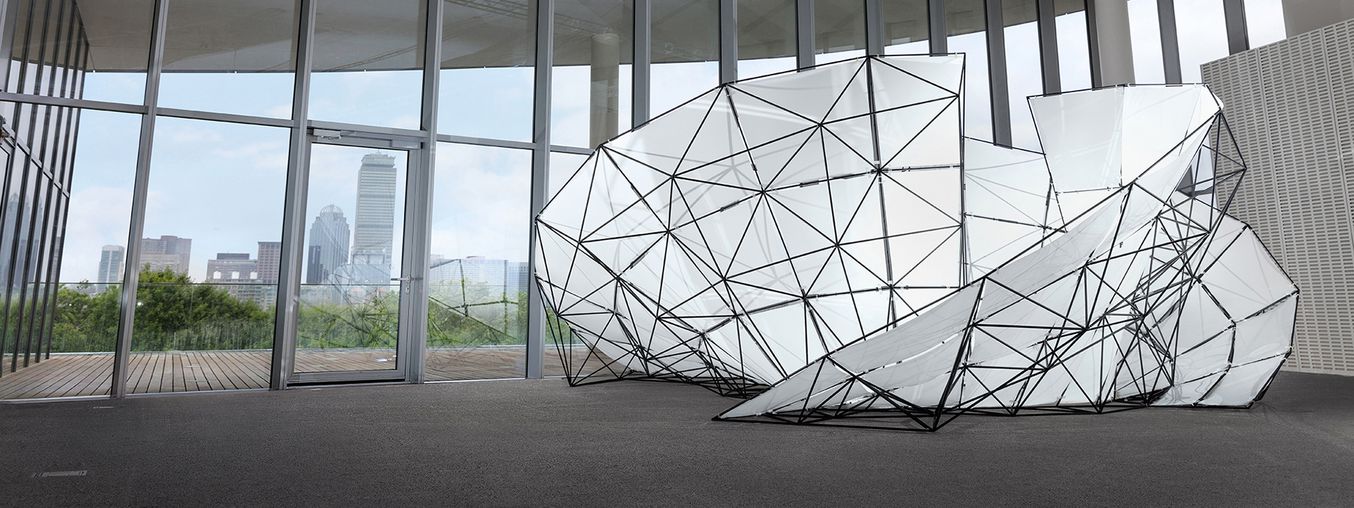
This pavilion has become the largest of the structures known to us, created from Formlabs parts - 4.5 m wide and 2.5 m high, it easily accommodates three people inside.
Depending on the size you need, structural questions can be quite important. Some forms have the property of self-support, being created of a certain size and from a certain material, others require additional support inside or outside, to ensure rigidity and stability.
We chose materials that will help us create the desired structure, which protrudes quite strongly in all directions, and does not require support with cables or columns. The connectors were printed on a Formlabs Fuse 1 printer from Nylon 12, a lightweight, rigid, and extremely durable engineering thermoplastic.
For struts, we chose hollow fiberglass tubes. The heaviest part of the structure was dense polyethylene (HDPE) panels; they weighed almost 45 kg. Before adding panels, the entire pavilion could easily be raised by one person.
How to turn STL into a structure?
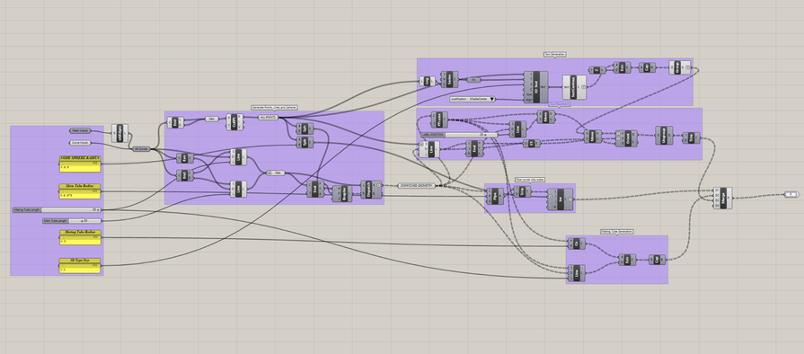
We used Rhino to turn the main surface of NURBS into a spatial framework , which gave the surface rigidity and structure. To create the shape, we used a parametric design, which allowed us to choose the “resolution” of the structure (the number of faces and edges approximating it) on the fly. This is important because resolution is closely related to the cost and complexity of the assembly.
At Rhino, we used Grasshopper's scripting system to create connector models and edge lengths. The module generation system works with a 3D grid, which can be drawn in any CAD editor. The script takes into account the corners with adjacent edges to prevent the intersection of our round edges. It also assigns a part number, which is then automatically applied to each connector.
Download Grasshopper script for Rhino
We optimized the shape of the connection nodes to reduce weight and print efficiency. A solid outer circular connector would be very durable, but it would use most of the material at the same time and take up the most space. The internal connector uses little material and prints the fastest.
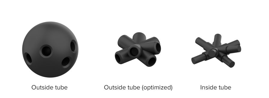
Three options for the pavilion connectors: external, optimized external, internal
It was much easier to get the desired shape from the panels - we used the Unroll function in Rhino to get a two-dimensional diagram for laser cutting from the surface. Filling the folder with connector models, a list of edge lengths and panel drawings, you can start creating the structure.
How to create hundreds of unique pieces?
All 144 connectors up to 8 cm in size made of Nylon 12 were printed in one go, lasting 36 hours. SLP technology does not require support for models, so the entire print volume can be used to print hundreds of unique parts at a time. We hope that the connectors of our pavilion symbolize the future possibilities of custom-made mass production, in which each part can meet unique requirements.
3D packaging
To fit 144 dissimilar parts into the print zone, technology is more complex than simply stacking them. Fortunately, using three-dimensional packing algorithms, we can calculate an optimized arrangement of parts in which they are all close to each other. This strategy has long been used to maximize the efficiency of SLP printers.
We tried several ready-made solutions, with varying success. Netfabb uses the Monte Carlo search for packaging, and yields the best results from all commercial solutions. We were able to fit about 50 nodes into Fuse 1. However, Netfabb had difficulty working with the non-convex geometry of our nodes, and the simulation took most of the day.
Ideally, the connectors should pack very close together so as to fill each other's concavities. To do this, we built a physical simulation on the Blender engine that packed the connectors into a virtual volume for printing. Nodes move and turn when they meet, and calm down when they do not overlap each other.
Parts randomly tremble until none of them overlap each other. The whole simulation takes about a minute.
We greatly accelerated the simulation using simplified intermediate models for counting collisions, rather than final high-resolution models. This method does not guarantee a mathematically optimal solution, but it works well. More importantly, we were able to fit almost three times as many nodes into the same working volume.
Already at the production stage, we used the advantages of parametric design to find the resolution for the parts, suitable for our time constraints and the entire project. Ideal resolution gives a good transfer of the initial curved shape, allows you to accommodate all the details in the print volume, and makes it possible to complete the project in a week. By speeding up the packaging of parts and increasing efficiency, we have achieved improved flexibility in the selection of the shape of the final structure.
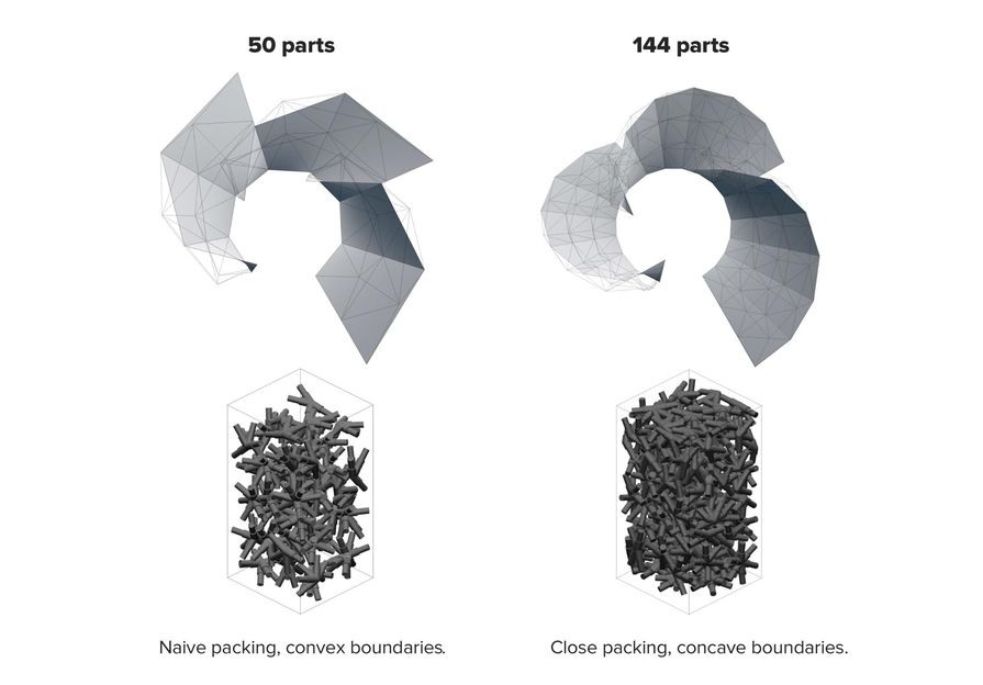
On the left is a naive package of convex parts, on the right is a dense package of non-convex parts.
After the conference, Michael Foglman, now at Formlabs, released an open source solution for three-dimensional packaging of parts. We will include automatic packaging in PreForm for Fuse 1.
High Volume Printing in SLA
To fix the panels, we could use ready-made fasteners, but the schedule and the geometric design features urged us on. We decided to make fasteners using laser stereolithography (SLA) from Durable Resin .
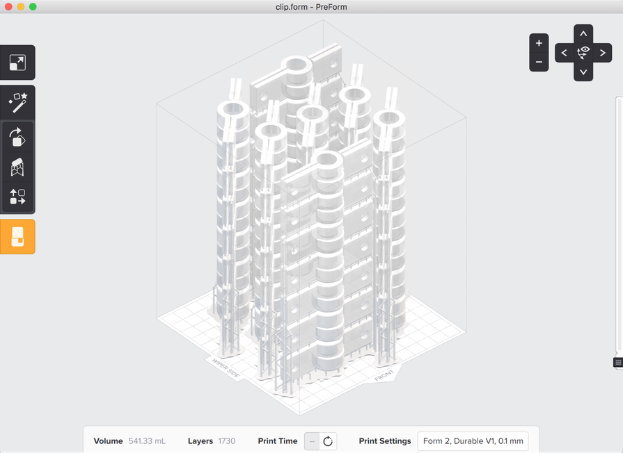
Over 500 fastener parts were printed in five sets on a Form 2 printer.
We used Form 2 to quickly create 505 brackets in a few days. We designed the parts in CAD so that they stacked, assigned the task of generating supports to PreForm, which allowed us to print 98 brackets in one pass. Tearing off part from the props was as easy as tearing perforated paper.
How to assemble a large set of parts?
The hardest part of creating a large modular structure is assembly.
Three people assembled the pavilion, working four hours a day. To facilitate the work, we sorted all the details in advance by projecting a three-dimensional diagram of the structure onto the wall. And still, the assembly has become a test for spatial thinking and patience. A simple search for the part and finding its correct orientation took a lot of time.
Working with a small budget and a rather modest structure, we decided to assemble the structure manually. But what if someone wants to build a larger structure, or increase its resolution? Robots can help them - machines are much better than people in moving parts to the exact position, and architects are already starting to create structures suitable for robotic assembly.
The future of digital manufacturing and architecture
We, designers, imagine a future in which the transformation of a digital spatial concept into a real design will be easy and automatic, like 3D printing. The system used to build the FUSE pavilion can be applied to the design of rooms, furniture, sculptures, etc. By combining advanced design methods with digital production devices such as Fuse 1, architects will not encounter any obstacles to the realization of any forms they can imagine.