Squirrel comes to people after talking with an electric meter
This summer in the country, at the end of August, having finally achieved a normal exchange of the device, which will be described below, with an electric meter, I sat on the porch and listened to the conversation of two squirrels, one sitting on a large thuja, and the second on an apple tree. Then my friend called, having just returned from a caravan to the White Sea. To his question, "how are you?" I answered, still immersed in the project: "I talked to the counter, I sit here, listening to the conversation of two squirrels." A friend was silent and said: “Well, about the squirrels after a liter of drunk, I certainly know, but after talking with the counter ???” :)
The article describes a device (hereinafter referred to as the "Talker"), designed to take readings from an electric meter and speak them with a synthesized voice into a telephone line. In addition to the actual readings of the consumed energy, Talker reads the current date, phase voltage, phase current, total and phase consumption and displays this data on the built-in TFT display. Also, temperature, humidity, atmospheric pressure and light sensors are connected to the Talker.
In fig. 1 shows a photograph of the device. The following nodes are marked with white numbers:
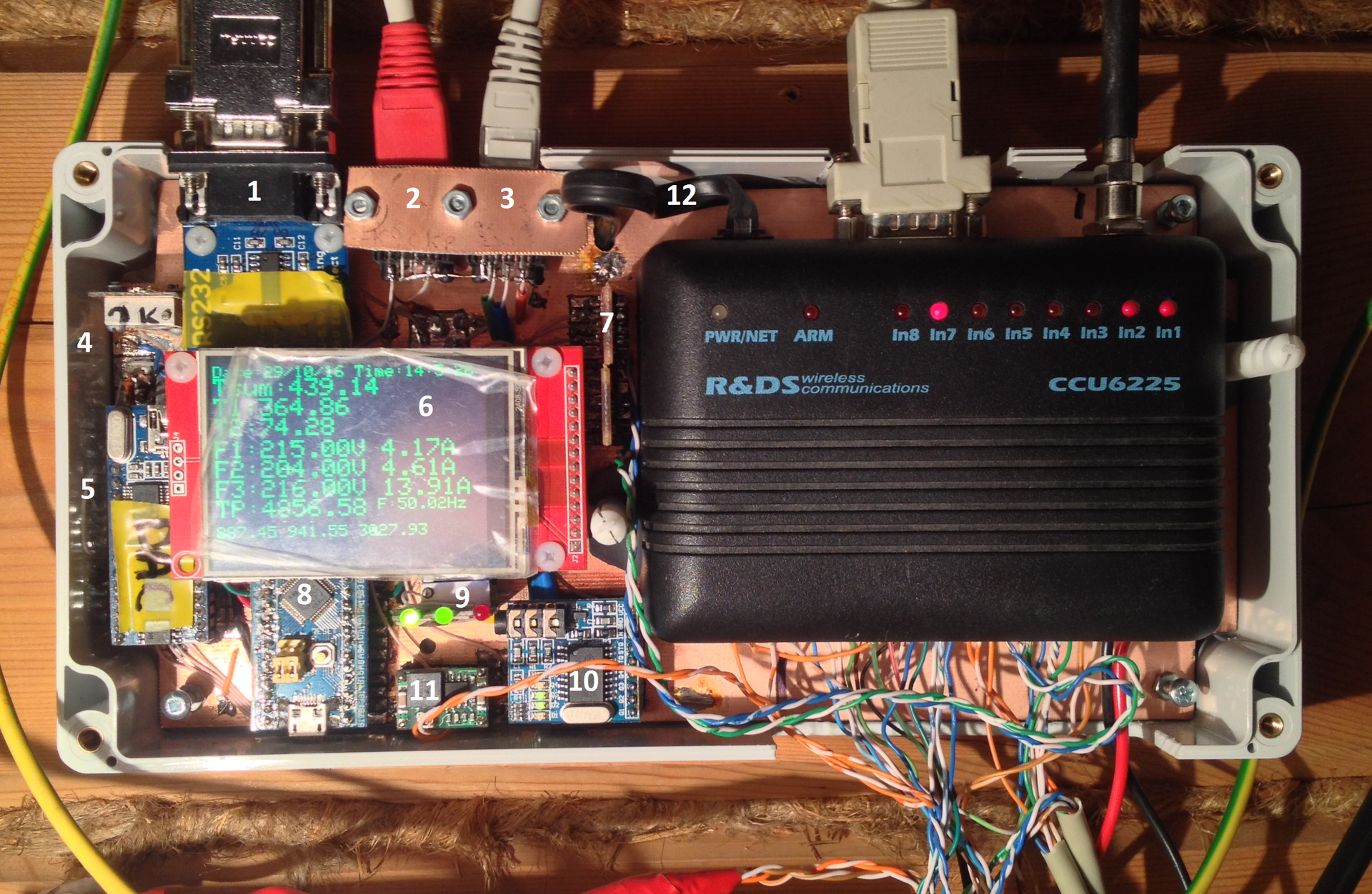
Fig. 1 Appearance of the Talker
The G2113C case was used with dimensions of 240x120x60mm, with a transparent cover. In the photo, the case is shown without a transparent cover. A photograph of the device with a cover is shown in Fig. 2.
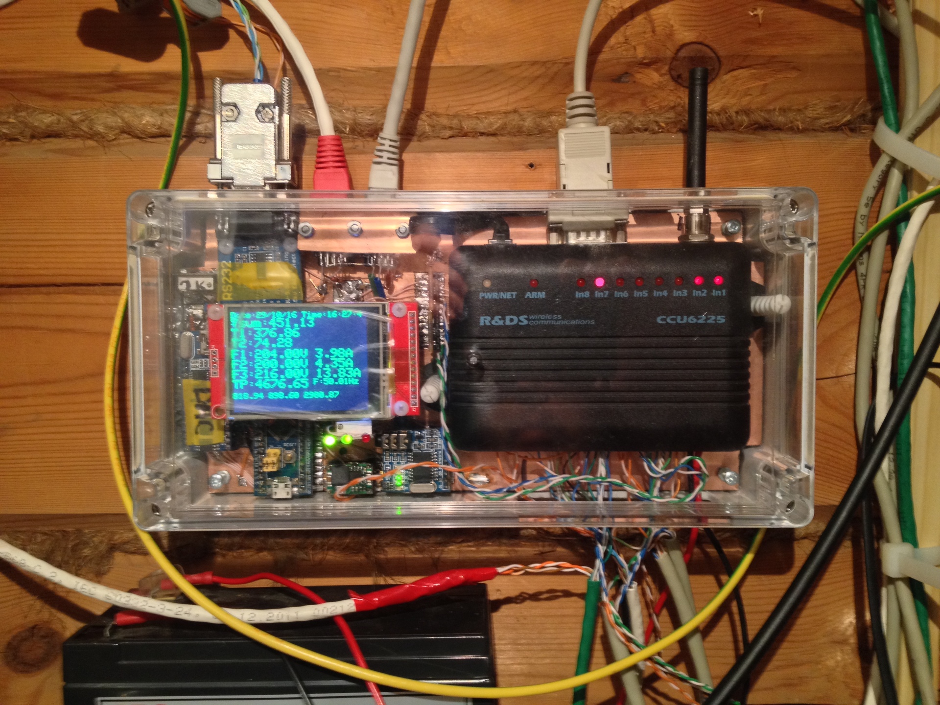
Fig. 2 A device in an assembled building
The need for this device appeared after the conclusion of an individual contract with MOESK for power supply as a result of the long work of our SNT chairman. This action entailed many consequences. To conclude an agreement with MOESK it is necessary to put a new meter in the metering board on the post. A new meter is therefore a new entrance to the house. Once a new supply - then why not take three phases and 15 kW for 500 rubles?
As a result, a new three-phase input of 15 kW appeared in the old country house, and all internal wiring in the house was replaced. A new shield appeared, in which in addition to the standard set of automatic machines and VDT (RCD), four contactors were mounted to control the supply of electricity. Three contactors control the inclusion of heating, the fourth - the supply of power to the lighting \ household sockets. When all four contactors are turned off, electricity remains only inside the steel closed panel, all external circuits are de-energized. Contactors are controlled by triac keys with optical isolation S202S02. Triacs are controlled from the CCU6225LT security controller of the Tula company RADS. The controller is probably 10 years old, it works flawlessly in 24 * 7 mode, controlling electric heating and forming SMS when door sensors are triggered. The only problem over the years has become the need to change the SIM card. At some point, the device disappeared from the network. Rearrangement of SIM cards from the phone to the device and vice versa showed that both SIM cards work in the phone, and in CCU6225 it is only fresh from the phone. Consultation with the provider and replacing the SIM card solved the problem completely. I also had to replace the lead backup battery, but 7 years is a good battery life.
CCU6225 makes it possible to control the load independently by SMS, by telephone via DTMF, or by a switch in the house. Several switches provided local control of the contactors, creating added convenience and flexibility in controlling home equipment. The switch "I am at home" made it possible to control through the CCU6225 a contactor for supplying power to the light circuit and household equipment. When leaving, it is enough to put him in the “I left” position and all the equipment in the house will be de-energized. Upon arrival - switch to the "I'm home" position and power will be supplied to all internal circuits. CCU6225 allows you to program the shutdown of circuits when leaving the house and the inclusion of only one (lighting) at the entrance. The point is that when leaving, you should turn off the heating, but not the fact that you must turn it on when you enter.
Also, four automatic devices are installed in the switchboard for emergency forced switching on of contactors by direct supply of current to the coils in parallel with triac switches. This is done in case of failure of either triacs or CCU6225.
The agreement with MOESK led to the need to testify the consumed electricity once a month. Those. once a month, take a meter reading. In summer, this is not a problem, but in the autumn, winter and spring, no one lives there and it is unreasonable to go to the cottage just for the sake of reading evidence.
The Mercury 231 counter has an infrared port for remote reading of readings; there is a program “Configurator” for communicating with such counters, i.e. the technical ability to electronically read the readings exists. The author of the "configurator" is a blog and is accessible by email.
For the transmission of testimony, there are ready-made industrial solutions (ASKUE systems) - both software and hardware. But they are expensive enough for a single non-commercial use and require the organization of a communication line. As a rule, some kind of cellular communication channel is used. Payment for such a channel for today is approximately 300 r per month. Those. for the transfer of 24 testimonies (I asked for a two-tariff mode at the conclusion of the contract), it will be necessary to pay 300 r * 12 = 3600 r for a year.
On the one hand, this is a bit. On the other hand - and this money must be earned. The technical redundancy of the Internet channel through cellular communication is also obvious. The house is insured, to consider the faces of the sorcerers, if that happens, does not make much sense, 24 * 7 control is not needed. For the transmission of testimony, the cheapest form of communication is desirable in order to pay at a minimum.
There is such an option - this is the audio channel in the existing CCU6225LT. An incoming call is free, it will take a minute or two to transmit testimony by voice, i.e. a few rubles a month will cost this mode of data transfer. Saving a couple of orders of magnitude is serious, despite the absolute values of the sums)
It turns out this scheme: you need to make a controller that will read the meter from the meter through the infrared port and speak it to the telephone line.
The Mercury 231 counter and infrared adapter are located in a shield on a column. From the shield to the Govorilka location, a twisted-pair FTP cable was laid in the house for outdoor use with a total length of about 35 m. A twisted-pair cable was laid simultaneously with the installation of a new meter and the replacement of a single-phase wiring to the house with a three-phase one. The cable consists of 4 standard twisted pairs in a common screen and a protective sheath in black. The black outer sheath is a sign of cable for outdoor use. Black plastic contains additives that increase the plastic's resistance to solar radiation. The infrared adapter is housed in a housing measuring 60 by 40 by 30 mm and looks like a standard RS232 port on the Talker side.
Magnets are glued to the body from the side opposite the hole for the infrared transceiver. This made it possible to attach the module opposite the counter on the inside of the shield door, simply by magnetizing it to the desired location.
On the reverse side of the cable in the house is mounted a protection device of five diodes of the type 1.5KE18CA (Bi-directional Protection Diode, 1500W, 18V, [DO-201]), a standard DB9 plug and a USB connector for supplying power to the infrared adapter. This is certainly not a complete lightning protection, but it can absorb some energy. In the Talker schematic diagram, the static protection device is designated as a “protection module”.
The standard RS232 connector and the standard USB connector make it possible, in addition to the Talker, to connect a regular laptop and use the “Configurator” program to, for example, adjust the clock or read meter data for monthly consumption analysis. I used this connection to watch the exchange of the program with the counter, to record the counter commands and counter responses. From the technical documentation available on the network, it is not always possible to correctly understand which command should be issued to the counter and how to correctly decrypt the answer. Comparing the memorized screenshots, for example, reading energy or current from the meter and the memorized byte exchange, it is enough to simply select a command and decrypt the answers.
Along the way, I note that with a laptop with a sniffer program it is very convenient to watch the Talker and counter exchange when debugging the sketch, it is enough to connect the Speaker RX input and the laptop RX input in parallel. I used Wago electrical quick-release terminals in three and five positions to make these connections. A photo of such a terminal is shown in Fig. 3. These terminals turned out to be extremely convenient for quick installation of twisted pair connections.

Fig. 3 Terminal Wago
At this design stage, I thought about the basis of the Talker - on what element base to make the system? There are several options:
• Use an old computer from availability, take data and speak software.
• Use something based on Arduino.
The first option is interesting because of its low laboriousness of development and huge opportunities for expanding the functionality. But since the house is not heated in winter, it is necessary to ensure the operation of the computer even at very low temperatures. And not so much work in itself, as restarting the computer after the power cut. This happens infrequently, but once a month the electricity disappears for a time sufficient for the computer to cool to ambient temperature. Starting a computer at temperatures below +5 degrees Celsius is problematic.
The first serious problem is the start of the hard drive. In the manuals indicate the permissible range of +5 degrees. Those. at lower temperatures, nothing is guaranteed. Personal experience of operating the server on the balcony also says that hard drives do not start at low temperatures. The reasons are commonplace - thickening of the grease in the bearings and insufficient torque of the spindle motor to move from the place of the pancake pack. This phenomenon is aggravated for a nenovy, working hard drive.
The second problem is a sharp change in the parameters of electro-radio elements (ERE) with a drop in temperature. So, we can expect a sharp deterioration in the capacitance of various capacitors in the power circuits, which will lead to a noticeable increase in the level of interference in the power circuits at low temperatures and possibly to other strange effects, such as instability, freezes, etc., for a stand-alone and remote computer unacceptable. Household computers are designed for use at positive temperatures and it is unnecessarily wasteful to put EREs with a large temperature range in them.
Obviously, both of these problems can be circumvented by placing the computer in a thermostabilized casing and, possibly, adding a watchdog timer to restart the frozen machine. But this is already too expensive a decision. Replacing a conventional hard drive with an SSD also does not make sense to consider - it is impractical expensive.
When using Arduino, there are no such problems - there are no disks there, the crystal itself is designed to work from -40 to + 105С °, and filtering capacitors for power are easily duplicated by elements suitable for operation in an extended temperature range. Watchdog is already integrated.
There is a third problem. Since the expansion of remote control capabilities is being done, it is reasonable to stop not only from reading the meter readings, but also to put several other sensors - temperature inside and outside the house, humidity, light, atmospheric pressure. All these sensors usually have an interface like I2C or 1Wire, i.e. one way or another, a converter of data received through these interfaces into computer-friendly ones is required. One reasonable option is Arduino.
Thus, it turns out that it is reasonable to use Arduino to read the counter and all connected sensors and transmit them by voice over the CCU6225 voice channel.
I could use the standard Arduin Nano on the ATMEL 328p processor, but I had 4 boards on the STM32F103C8T6 processor (Fig. 4) and I decided that it would be interesting to use this more advanced 32-bit processor. STM32F103C8T6 has 64 KB of flash memory for the program and 20 KB of RAM and can operate at a clock frequency of 72 MHz. In reality, flash memory is more than double. On the forum there have been reports about the success of the modules and programs when you select "128 KB of memory."
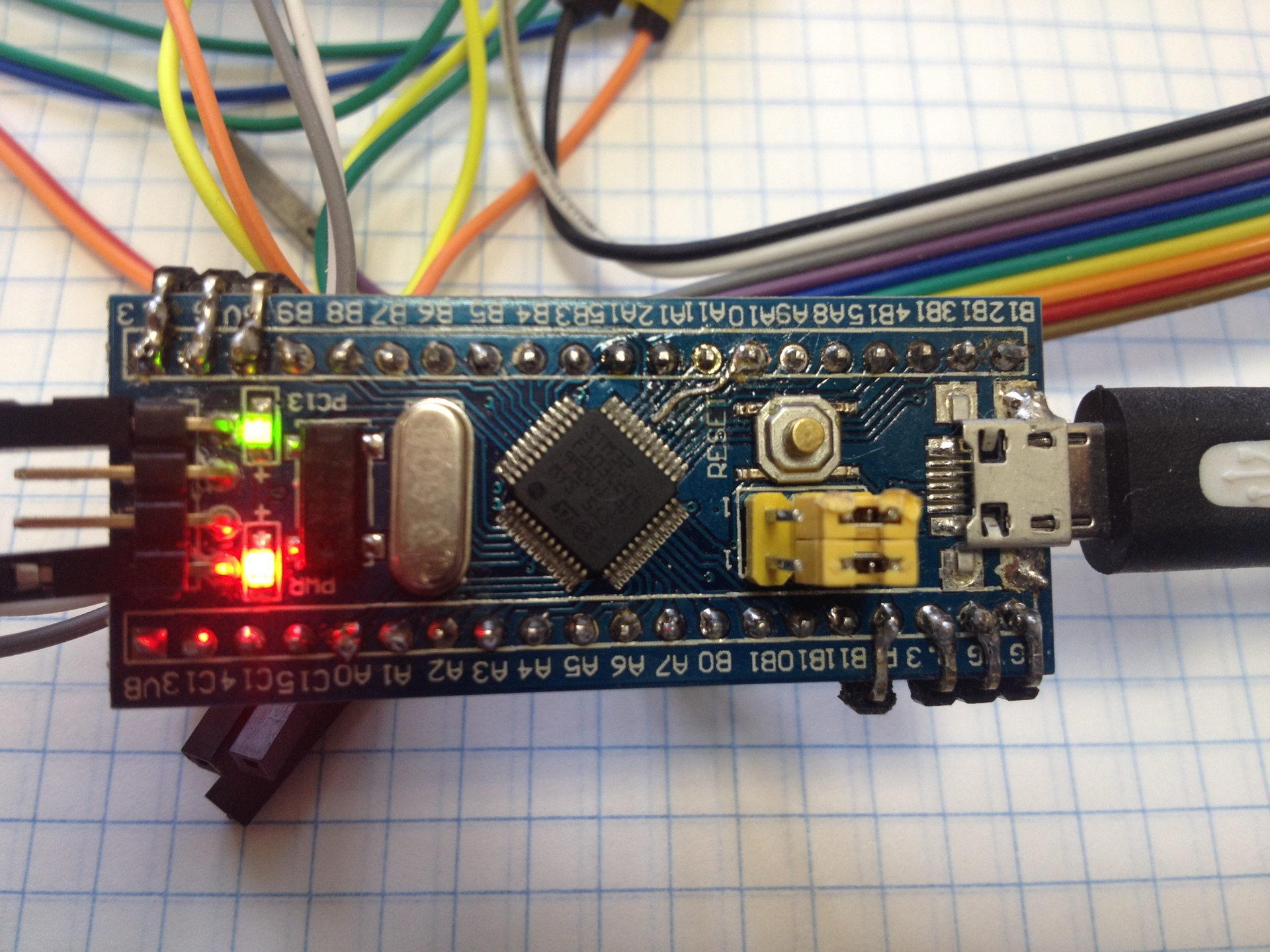
Fig. 4 Appearance of the board on the STM32F103C8T6 processor (Blue Pill)
STM32F103C8T6 boards come without a bootloader, but the bootloader firmware procedure is simple, after which the board can be programmed using the standard Arduin IDE. On the forum www.stm32duino.comThere is a detailed description of the steps you need to take to install the IDE and bootloader firmware.
The board (“Blue pill”) with STM32F103C8T6 has a quartz clock (32768 Hz) on board and can store the current time when a backup battery with a voltage of about 3V is connected to the VBATT terminal. In my project, this feature is not used, because time can be read from the counter.
At the time of making the decision on the Talking platform, I did not yet have real experience with the STM32F103C8T6 processor. Nevertheless, I decided to use this particular processor and did not regret it - it turned out to be no more difficult to work with it than with Atmel328p, and there are much more possibilities and resources, the processor is faster. Working with the display turned out to be easier - no level 5 - 3.3 volt converters are needed, all sensors are also connected directly. The image on the screen is formed much faster even in the normal exchange mode without using DMA.
In fig. 5 shows the electrical circuit diagram.
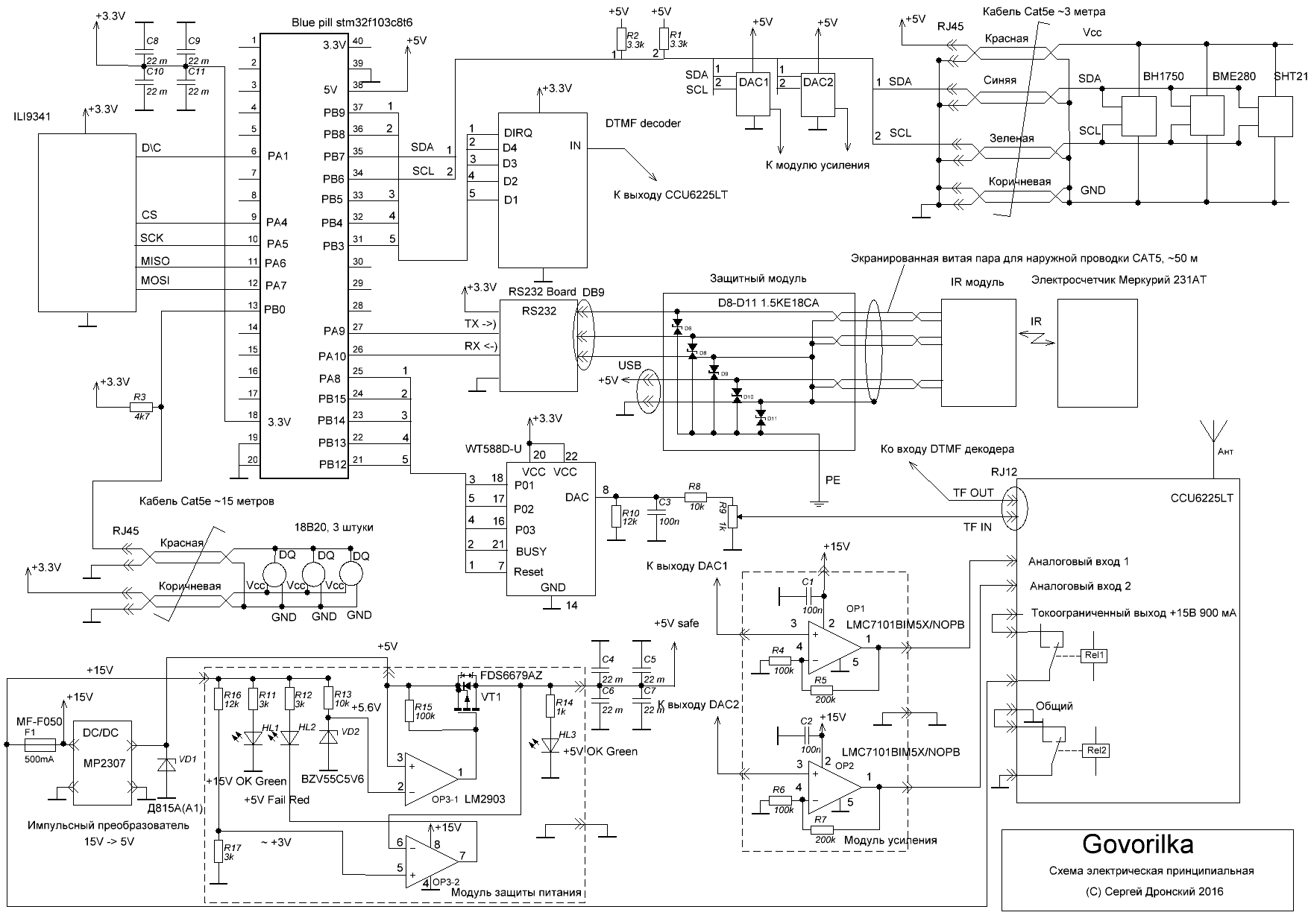
Fig. 5 Talker. Schematic diagram
The STM32F103C8T6 has two I2C hardware controllers and I wanted to distribute different groups of sensors on different channels. So, on one channel I wanted to connect the external temperature and humidity sensors, and on the second - the rest, located inside the Govorilka case. In this way, I wanted to increase the reliability and survivability of the system, so that in case of collisions with external sensors, only one channel would fail, and everything else would remain operational. The first channel started working immediately and without any problems (on the outputs of PB6, PB7), both in hardware mode with a clock frequency of 400 KHz, and using software exchange. It was not easy to start the second I2C channel (on pins PB10, PB11) using the HARDWIRE library adapted for Blue Pill. Now I believe that the HARDWIRE library has features that are manifested precisely when working with the second channel. After a long struggle, I2C managed to launch the second channel. The situation is paradoxical - when you connect a sensor to the first channel and load a test program, for example, an I2C scanner, everything works right away. Switching the sensor to the second channel and replacing the number 1 with the number 2 in the object creation command (HardWire H2Wire (2, I2C_FAST_MODE);) leads to the complete inoperability of the system. The board hangs tightly and is removed from this state only with the Reset button. Detailed studies of the problem with the use of debugging points after each operator and logic analyzer to view the signals generated on the I2C2 bus made it possible to find the point of hovering and eliminate it. For me, the solution to the problem was to set the exact size of all critical variables used in I2C2 exchange (int16_t instead of int, etc.). I’ll very carefully assume that the wrong size of the variables used for exchanging with the HARDWIRE library routines leads to writing (or reading) of incorrect memory areas, which in turn gives unpredictable results. Why this is manifested when using the second channel I2C and does not appear when using the first - I do not know. Also, this hypothesis does not explain the oddities with the SDA and SCL signals, one of which, when loading the sketch, went to zero and remained there until the reset. How this is connected with the declaration of variables and their different sizes - I can’t even imagine. Why this is manifested when using the second channel I2C and does not appear when using the first - I do not know. Also, this hypothesis does not explain the oddities with the SDA and SCL signals, one of which, when loading the sketch, went to zero and remained there until the reset. How this is connected with the declaration of variables and their different sizes - I can’t even imagine. Why this is manifested when using the second channel I2C and does not appear when using the first - I do not know. Also, this hypothesis does not explain the oddities with the SDA and SCL signals, one of which, when loading the sketch, went to zero and remained there until the reset. How this is connected with the declaration of variables and their different sizes - I can’t even imagine.
After analyzing all the desires (aka Wishlist), it became clear that there were a lot of phrases for pronunciation (up to a hundred). In the current version, 76 fragments were used. To use Arduino's small memory for this is unreasonable. A search on an Internet of ways to generate sound yielded unexpectedly remarkable results: on the Internet there are WT588D-U modules with 32 megabytes of memory that can store up to 220 fragments of sound with a total duration of several minutes at the best quality. The modules are equipped with a mini USB connector and can work in different modes: play sound on command from the MK, from the buttons. A photo of the module is shown in Fig. 10 poses 1. The module has a built-in 13-bit DAC and a PWM amplifier for a 0.5 W speaker at 8 ohms. This module only understands the WAV format with a sampling frequency of 6 to 22 kHz. Module supply voltage 2.8 - 5.5 volts, pairing with MK - 3.3 volts. If you need to use MK with logical levels of 5 volts - you need to use a converter (suitable from the simplest resistor dividers to microcircuit).
The software module can be controlled either via a single-wire interface or through a three-wire interface. More details here. An interesting feature of the module is the method of generating sound fragments: they can consist of an arbitrary number of sounds and pauses loaded into the memory. Pauses in memory do not take, i.e. many atomic sounds can be loaded into memory and various fragments can be constructed from them, variously connecting the same sounds. To play back a specific fragment (or voice, as it is called in the manual), you need to transfer the number of this fragment to the module, wait for the BUSY signal to appear and wait for the BUSY signal to disappear. It is in this sequence that the BUSY signal appears with a rather large delay after receiving the command. The specific type of BUSY signal (low, high, open collector) is determined when creating a project. You can switch these options in the finished project, but you need to recompile the project again before writing to the module. Jackdaw “Pull high resistor” (Fig. 5) controls the type of output “Busy” - a full push-pull push-pull or an open collector. The OK mode is useful when a signal LED is connected, and push-pull is useful when a signal is sent to the control MK. The project is created by a program that can be downloaded, for example,here (version 1.6 beta) or find it on the internet yourself. There is version 1.0.
I used version 1.6 beta, simply because it fell into my hands first. The speaking mode I used is simplified. So, numbers are spoken simply by one digit without dividing into hundreds, thousands, genders and declensions are not taken into account, etc. For example, the number 397.45 will be spoken as “Three nine seven point four five”, and the phrase about the number of 18b20 sensors detected will look so: "one temperature sensor was detected." This method uses the property of significant information redundancy of the Russian language, the unambiguity of perception of information by ear does not decrease, although incorrect cases and declensions certainly cut the ear. But the simplicity of programming this mode outweighed the desire to make an academically correct pronunciation. I note that there is no rocket science in programming the correct declensions and conjugations, there are lots of examples where numbers are converted into numbers in words, in all conceivable options: from expert tables and macros in Excel to stand-alone dlls in C, but the complexity of the question is great. Based on these factors, I decided to simplify as much as possible the actual pronunciation program at the first stage of work, paying maximum attention to the functioning of the program as a whole and leaving second-order modifications for classes on dark winter evenings :). There is enough free memory in WT588D-U and STM32F103C8T6 for any conceivable delights in organizing the correct pronunciation. In fig. Figure 5 in the lower right corner shows that my entire project took less than 23% of the memory of the WT588D-U module with a total duration of all fragments 78 seconds. from expert tables and macros in Excel to stand-alone dlls in C, but the complexity of the question is great. Based on these factors, I decided to simplify as much as possible the actual pronunciation program at the first stage of work, paying maximum attention to the functioning of the program as a whole and leaving second-order modifications for classes on dark winter evenings :). There is enough free memory in WT588D-U and STM32F103C8T6 for any conceivable delights in organizing the correct pronunciation. In fig. Figure 5 in the lower right corner shows that my entire project took less than 23% of the memory of the WT588D-U module with a total duration of all fragments of 78 seconds. from expert tables and macros in Excel to stand-alone dlls in C, but the complexity of the question is great. Based on these factors, I decided to simplify as much as possible the actual pronunciation program at the first stage of work, paying maximum attention to the functioning of the program as a whole and leaving second-order modifications for classes on dark winter evenings :). There is enough free memory in WT588D-U and STM32F103C8T6 for any conceivable delights in organizing the correct pronunciation. In fig. Figure 5 in the lower right corner shows that my entire project took less than 23% of the memory of the WT588D-U module with a total duration of all fragments of 78 seconds. paying maximum attention to the functioning of the program as a whole and leaving second-order modifications for practicing on dark winter evenings :). There is enough free memory in WT588D-U and STM32F103C8T6 for any conceivable delights in organizing the correct pronunciation. In fig. Figure 5 in the lower right corner shows that my entire project took less than 23% of the memory of the WT588D-U module with a total duration of all fragments of 78 seconds. paying maximum attention to the functioning of the program as a whole and leaving second-order modifications for practicing on dark winter evenings :). There is enough free memory in WT588D-U and STM32F103C8T6 for any conceivable delights in organizing the correct pronunciation. In fig. Figure 5 in the lower right corner shows that my entire project took less than 23% of the memory of the WT588D-U module with a total duration of all fragments of 78 seconds.
You can try to record sound files yourself or generate one of the speech synthesis programs. Having some experience in recording greetings for office telephone exchanges, I chose the second option without hesitation. Experience says that it’s not easy to make a high-quality sound file yourself - you need a good studio microphone, a room with good sound insulation and some pronunciation training. Among the Internet projects with the synthesis of the Russian voice, I liked Yvonne the most.
I have prepared a list of phrasesand in a short time received a set of necessary sounds. There are some drawbacks: in some phrases accents are incorrect, some words are pronounced unusually. For example, the word "ampѐr" the machine says, as "ampere". The intelligibility of phrases is very good, and I turned a blind eye to the listed shortcomings, although there are probably ways to fine-tune speech synthesizers that will achieve the perfect result. The main task of the Talker is to legibly pronounce the consumption figures and the output of the sensors.
I converted the resulting files to WAV format with a converter from the AIMP complex. By trial and error, it turned out that in the batch converter it is necessary to explicitly specify all parameters of the output file, explicitly including all options, otherwise the data logger in wt588 does not allow importing a file with the message “invalid format”. I did not understand in detail, perhaps the problem is the absence of any parameter in the file header, which the import program perceives as an incorrect format. Naturally, you can use a variety of online converters.
Along the way, it turned out that there are no problems with the Cyrillic alphabet in the file names.
Working with this program has some features. First you need to create a project (Fig. 6).
In the project on the left panel you need to type sound files. These are the original sounds from which fragments can be constructed. Sound files are required in WAV format with a sampling frequency of 6 to 22 kHz in 2 kHz steps. When importing a file, the program checks these parameters and will not allow importing a file with an invalid sampling rate.
To create a fragment in the right part, select the fragment number (Equation No) and type files from the left panel in the lines of the right panel. A fragment can include just one sound file from the right panel or consist of many sounds and pauses. In different positions on the right, you can type the same files from the left panel. Those. inside the module one copy of the file is stored and it can be used in several fragments. In my project, all fragments contain only one sound file. To start playback, for example, fragment number 0xD0, you need to transfer the 0xD0 command to the module.
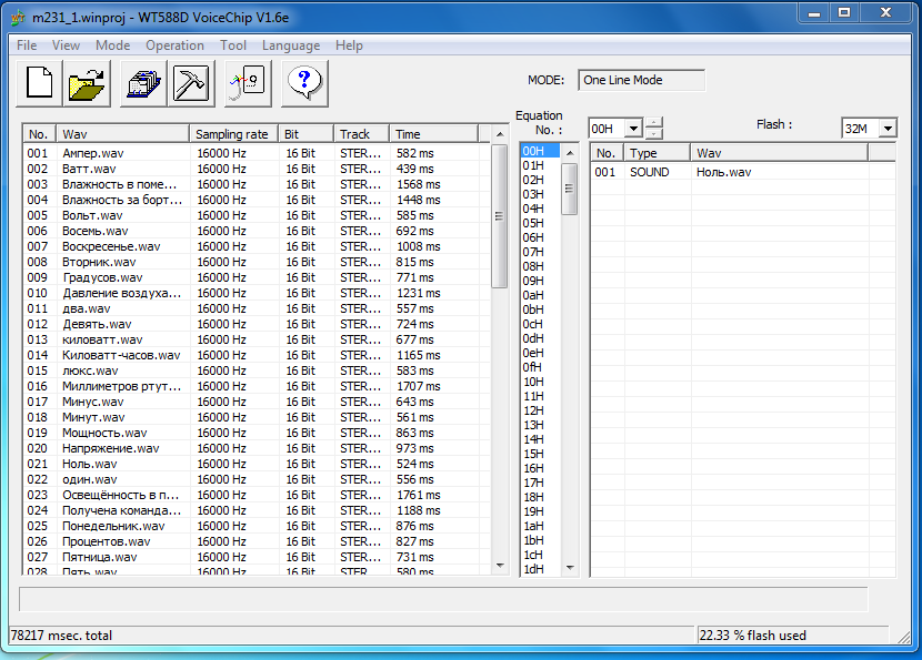
Fig. 6 Screenshot of the project
While the fragment is playing - the BUSY output is pressed to zero (or vice versa - to power, an option in the settings). In fig. 7 presents the options for creating a project.
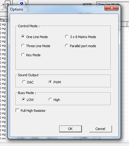
Fig. 7 Project creation
options Also in the project options you can also specify the type of output device - DAC (DAC) or PWM amplifier. The DAC output should not be fed to the speaker; an additional amplifier should be used.
I didn’t do the amplifier, but I prepared two projects - one with the DAC, the other with PWM and rearranged the modules in Talker during debugging. In the modules of the next generations, both outputs work simultaneously - i.e. You can also connect a speaker and use the DAC output. After creating the project and a set of necessary fragments, you need to compile the project. In fig. 8 shows the result of compiling the project.
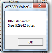
Fig. 8 The result of compiling the project
Next, you need to connect the module to the computer and open the module using the “Connect” button (the “Status” indicator will turn green), erase the module’s memory (“Erase”) and save the project (“Download”). You can do this with a single “OnekeyDownLoad” button.
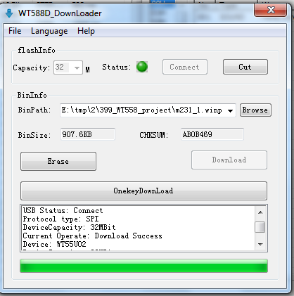
Fig. 9 Writing a project to the module The
finished project can be downloaded here .
Searching the Internet for a ready-made library for managing the WT588 yielded rather scanty results - there was one acceptable library that works with the module in the 3-wire interface mode. The module can be controlled from the processor either via a single-wire interface or via a three-wire interface. In reality, you still need to read the status of the BUSY pin and control the CS pin, i.e. In total, 5 conclusions from MK are needed. What is called a “single-wire interface” in the Chinese manual actually requires three MC outputs.
The module worked in the test circuit, but an unpleasant feature was found out - if the system was turned off and on, the module stopped responding to commands. Experimentally, I found out that it is necessary to turn off the power for more than 30 seconds, after which the module works again. Manipulations with the “reset” output did not help, the module did not react to this at all. Finding nothing on the Internet about this problem, I wrote a letter to Sound Technologies to request technical support. To my surprise, I received a perfectly sane answer. It turned out that there were several modifications of the WT588D-U modules and earlier versions were just different in the behavior I noticed when I quickly turned off the power supply. It became clear the low price of the modules I bought :)
When discussing issues, a colleague from “Sound Technologies” said that now there are more interesting models of this company, we talked and he sent me several modules for testing. Photos of the modules are shown in Fig. 10.
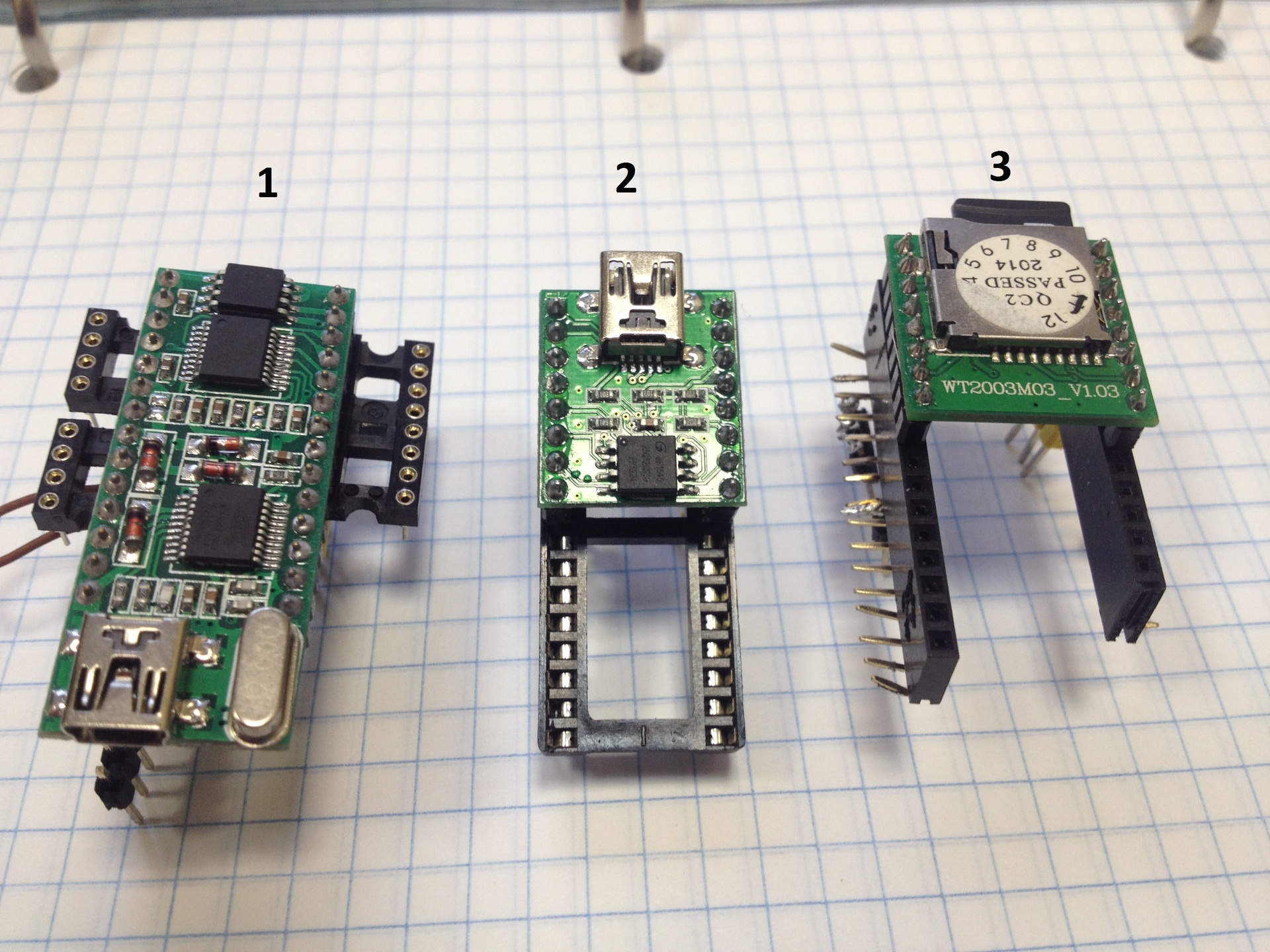
Fig. 10 Sound-reproducing modules, 1 - WT588D-U, 2 - WT200302, 3 - WT2003M03
The sent WT588D – U module did not really freeze when the power was turned off / on quickly. Outwardly, the new and the old are exactly the same, I carefully compared them under a microscope, the capacitors are apparently different in the circuits of the formation of the reset pulse when applying power.
The package also included new modules, more interesting. So, the WT200302 module with built-in flash memory (Fig. 10 pos. 2) is two times smaller, works with the MP3 format, and does not require a separate programmer. The maximum number of sound fragments has been significantly increased - 3584. It is very simple to program it - just connect the module to a computer via USB and record the desired sound files like a regular USB flash drive. The module is controlled simultaneously by buttons and commands on a single wire. Three-wire control mode is not. Just like its predecessor, the BUSY output is active while the sound file is playing. Unlike the previous module, BUSY is only low, i.e. when the sound is played, the BUSY signal drops to zero. The module has a curious feature - when connected via USB, it becomes a sound card, i.e.
Another WT2003M03 module (Fig. 10 pos. 3) can work with a standard micro-flash card ranging in size from 32 mb to 32 gb. It is controlled in the same way - on one wire. The module’s capabilities are even wider: it supports both WAV and MP3 and can use up to 65487 fragments.
The package also included modules in a minimalist design and a programmer for them, the photo is shown in Fig. 11. These modules contain the necessary hardware minimum - one flash memory chip and wt588 control controller. To program them, an external controller is required. They can be used with stringent requirements for cost and size of the device. Details, configuration details, possible supply voltages, etc. technical information is abundantly presented here .
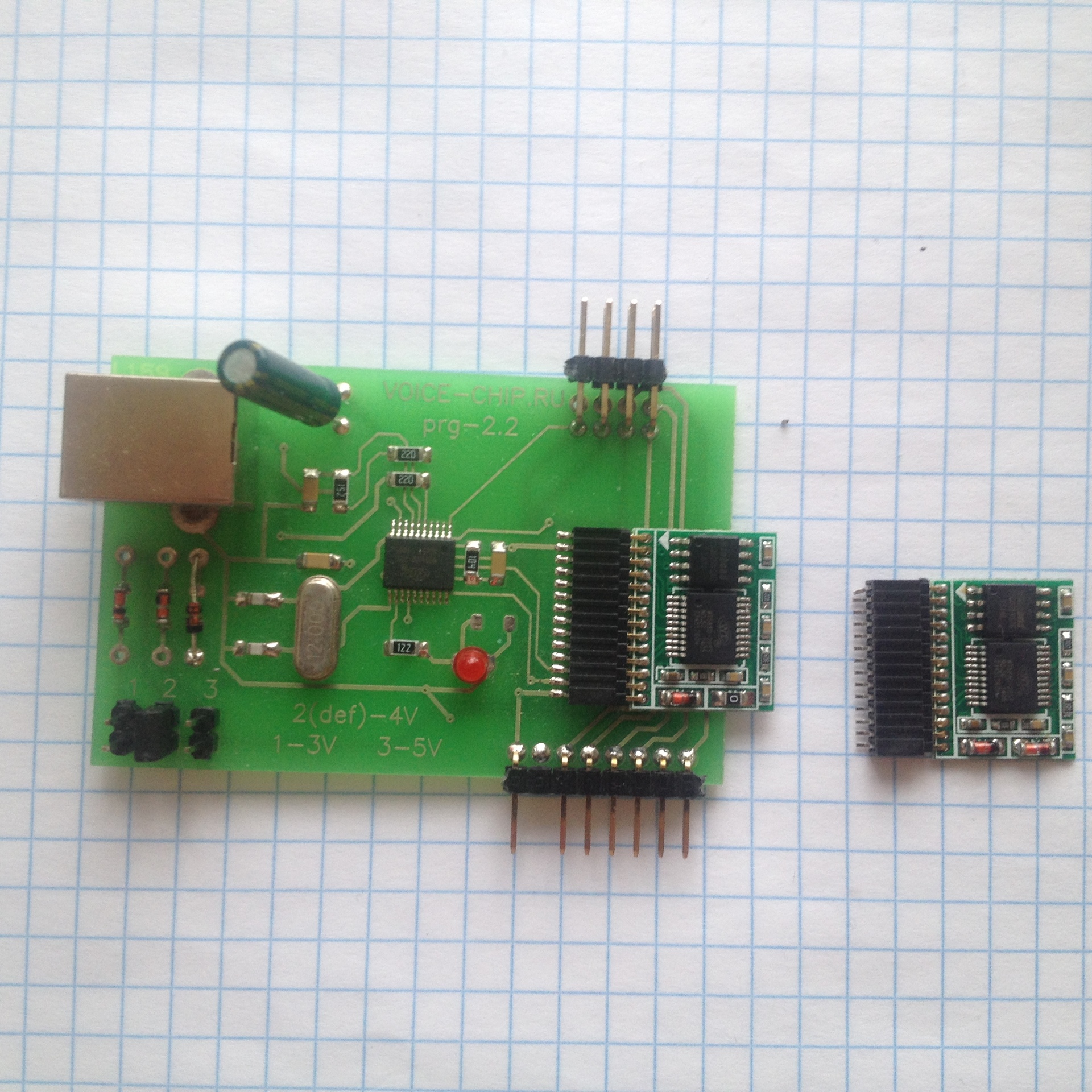
Fig. 11 Minimalist Modules
All sound modules have round-legged connectors (DIP collets) that barely stick to DIN rails. I did not find such connectors in the household, it is unreasonable to specifically buy them. Therefore, for testing purposes, the already existing small connectors were adapted.
To use the independent module in Govorilka I rewired the connector. Since I don’t have equipment for soldering such connectors, I did this: first I cut the connector on the board into small parts with side cutters, then I removed these parts, cleaned the holes with a steel needle and sealed the new DIN connector with standard square legs that fit tightly into the connector on the board.
Technological hint: cleaning the holes filled with solder with a steel needle is done like this: the hole heats up even without flux! (this is important) a steel needle is quickly inserted into the hole. The tin solidifies with a tube, the needle is removed - the hole is ready. Solder without flux sticks poorly to a steel needle, which allows you to re-form holes in the printed circuit board. If the tin begins to stick, it is enough to rotate the cooled down needle in the fingers, a thin layer of fat from the hands will worsen the wettability of the surface of the needle with solder. If there is a vacuum desoldering pump - everything is much simpler :)
After debugging Talker, I started connecting the WT588D-U module via a single-wire interface. During debugging using a logical analyzer, two inaccuracies were found in the manual. The first problem is that after the command is received, the module sets the BUSY signal after about 34 ms (and not 5, as in the manual). The second - the RESET pin cannot be left unconnected, it must be connected either to the 3.3 V power supply or to the MK output. This is, on the one hand, a general rule, on the other - it is always clearly written about in manuals.
I didn’t think of it right away and for a long time I could not understand why the system makes a strange wheezing sound instead of normal phrases.
The WT2003M2 and M3 modules differ from the WT588 in the size of the control word and the order of bit transmission in the word. For WT588, the control word is 8 bits and the low-order bit must be transmitted first, while for WT2003M2 and M3 the word is 16-bit and the highest bit must be transmitted first.
The delay times of sound output and the BUSY output response are also different - for the WT588, the delay relative to the last bit of the command is about 30 ms (the manual mistakenly indicates 5 ms), for WT2003M2 and M3 - about 200 ms. These delays must be taken into account if the program constructs composite phrases, for example, “temperature overboard” + “two” + “five” + “degrees”. To prevent phrases from running into each other, you need to start playing the first phrase, wait for it to finish analyzing the appearance and disappearance of the BUSY signal, start the next phrase, etc. In my case, the analysis of BUSY and waiting for the end of the playback are embedded in the playback routine.
It was possible to launch the WT2003M2 and M3 boards via a single-wire channel by changing the order in which the command bits are issued. According to the manual it is necessary to output the least bit forward. In fact - the eldest bit forward. Archives with test programs for modules - here . The test program provides a start pulse for the logic analyzer to see what is actually being formed on the control terminal and when the BUSY signal actually appears and disappears.
The WT2003M2 and M3 modules turned out to be rather moody to the parameters of MP3 files. Converted from wav are pronounced in slow motion. Received from text-to-speech on-line converters are pronounced with “swallowing” of the last syllable. Naturally, all files play normally on the computer. The phenomenon of "swallowing" takes place both when a command from MK and when starting playback with a button. However, these are second-order inaccuracies, and you can probably pick up mp3 parameters that will be all right, add silence before and / or after the fragment. The problem is obviously related to the low speed of the mp3 decoder and can be considered as implementation features: “this is not a bug, this is a feature”.
The last feature of these modules, which should be mentioned, is that the signal from the PWM (i.e., directly from the speaker) should not be fed to the input of the cellular module. The result will be terrible. The signal from the DAC should be fed to the input of the cellular module after the corresponding filtering circuits. In my scheme, the signal is further attenuated to a level corresponding to the level of a standard microphone, i.e. 20-30 mV. At the output of the DAC, the signal has a span close to the power level, i.e. 3 volts. I mention this for this reason: at first I wanted to make a universal option so that the sound would go both to the cellular module and to the speaker, if necessary. I made a circuit for supplying a PWM signal to a speaker or a load resistor through a switch and filtered the same signal for feeding to a cellular module. Practical testing showed that simple means to filter the PWM signal to an acceptable state does not work, the cellular module is clogged by the input and the result is terrible. The reasons are clear - the speaker, being a slow mechanical system, effectively integrates the PWM signal without reacting to higher harmonics. But the system for processing the audio signal of the cellular module turned out to be very sensitive to impulse noise. Acceptable sound quality is achieved only when using the DAC output and the manufacture of the subsequent filter circuit in accordance with the manual. The cellular module is not very sensitive to the signal level, the quality and level of the signal on the dynamics of the cell phone is practically independent of the signal level at the input of the cellular module. When adjusting the level with the R9 resistor, it is necessary to take into account the large delay of the cellular path - approximately 200-300 mS according to my estimation. In cellular communication, a very effective AGC system, a change in the signal level at the input of the cellular module at the signal volume at the output of the receiver’s cell phone is not reflected at all. However, adjusting the level with a variable resistor turned out to be useful - despite the excellent operation of the AGC system, you can find a signal level at the input of the cellular module at which the sound quality at the output (i.e., on the speaker of the telephone receiver) is the best. I want to note that the range in which the signal at the output of the entire path is the best is quite small, literally several revolutions of the tuning multi-turn resistor SP5-3. However, adjusting the level with a variable resistor turned out to be useful - despite the excellent operation of the AGC system, you can find a signal level at the input of the cellular module at which the sound quality at the output (i.e., on the speaker of the telephone receiver) is the best. I want to note that the range in which the signal at the output of the entire path is the best is quite small, literally several revolutions of the tuning multi-turn resistor SP5-3. However, adjusting the level with a variable resistor turned out to be useful - despite the excellent operation of the AGC system, you can find a signal level at the input of the cellular module at which the sound quality at the output (i.e., on the speaker of the telephone receiver) is the best. I want to note that the range in which the signal at the output of the entire path is the best is quite small, literally several revolutions of the tuning multi-turn resistor SP5-3.
Since it was not possible to make a universal option for scoring, I settled on the option with the DAC, and for debugging I put the module into the socket in PWM mode. In principle, you can send a signal to the speaker through an additional amplifier, but in practice this turned out to be unnecessary. Everything interesting is displayed on the screen, and you can check the operation of the tract simply by calling.
To pair the MK and the RS232 channel, I bought a ready-made board in Chip and Deep (position 1 in Fig. 1). Board name: "RS232 Board, RS232 communication board, based on SP3232, 3-5.5V, ESD protection, hardware flow control." The board is a complete device that has a DB9 connector on one side and a connector with leads on the other: power (from 3 to 5 volts), common, input, output, hardware flow control lines. According to the specification, the board is somewhat resistant to static discharges. The board is additionally protected from impulse noise on incoming wires from the meter by diode-absorbers located in an additional external housing.
The talker and CCU6225 are mounted in one G2113C case, the case for CEA is 240x120x60mm, plastic, with a transparent cover. The basis was a board made of double-sided foil fiberglass 0.8 mm thick. On the board by the Dremel milling method, the places for mounting the connectors of the nodes were cut out. Also on the board are rectangular contact pads for supplying +3.3 and +5 volts to all nodes of the system. Filtering SMD capacitors with a nominal value of 22 microfarads per 16 volts are soldered around the perimeter of the power supply sites. The nodes are interconnected by wires of MGTF 0.12. It is not possible to place all the nodes in one plane in the selected case, therefore, some of the nodes are placed vertically (power control unit and DAC), part above the others (display).
The cable connecting the CCU6225LT audio connector and the signal conversion unit with the WT588D-U output DAC is passed under the board through two holes. This solution allowed to some extent protect the audio signal from pulse pickups.
The CCU6225LT module provides power to the Talker. The CCU6225LT has a current-limited output of +15 volt 900 mA and there are still a couple of idle relays with changeover contacts. Power can be supplied to the Talker through normally closed relay contacts. The relay is remotely controlled, which can be used to restart the Talker in case of emergency. It is also possible to turn on the Talker for reading only. In this case, the communication session will look like this: a call to the CCU6225LT, turning off the relay (the Talker is fed through normally closed contacts), switching to the microphone, listening to data, disconnecting from the microphone and turning on the Talker's power relay until the next communication session. I see no practical sense in using such a scenario and I mention it only for generality.
According to calculations, the talker was supposed to consume about 100-150 mA. On the finished device, the measured current was 110 mA. To reduce the voltage from 15 to 5 volts, it is reasonable to use a pulse converter. I did not really want to convert a volt * 0.2 A = 2 watts to a heat with a linear stabilizer (15-5). I chose an inexpensive module (Super mini 3A DC-DC 3V 5V 16V Converter Step Down buck Power Supply Module) based on a step-down converter with a synchronous rectifier (similar to MP2307), capable of (according to the seller) outputting current up to 3 ampere. Reviews of this module on MYSKY show that 3 amperes is just a dream, you can really count on 1A without overheating, plus there is no protection against short-circuit at the output and overheating. Apparently, the Chinese clone of the microcircuit is used in the module and the excess is thrown in it, i.e. protection.
However, in the absence of protection against overheating and short circuit, the module in case of failure, i.e. burn-out of the feed-through transistor, it will give all 15 volts to the output. This is dangerous, too much for MK and sensors. Therefore, I decided to apply overvoltage protection when the step-down converter fails. The protection consists of two independent mechanisms, each prevents a voltage of more than 5.6 volts from entering the power supply of the MK.
The first mechanism is made on half of the comparator LM2903 (OP3-1) and a powerful field key VT1. It turns on the power to the MK if the supply voltage at the converter output is not more than 5.6 volts and turns it off if the voltage is more than 5.6V.
The second mechanism consists of a powerful Soviet-made Zener diode D815A, connected in parallel at the output of the converter and a reusable thermal fuse (MF-F050), connected in series at the input of the converter. In the event of a converter failure and an increase in the output voltage of more than 5.6 V, the zener diode will open, a current will flow through it, which will lead to heating of the thermal fuse and power off to the Talker. The stabilization voltage of D815A is 5.6 volts, the permissible current is 1400 mA, which guarantees non-exceeding of the level of 5.6 volts. The permissible current for the zener diode significantly exceeds the threshold current of 900 mA from the power source (CCU6225). The thermal fuse will shut off noticeably before the zener diode warms up.
The second protection mechanism is disposable and disconnects the voltage irreversibly. To restore normal operation, you will most likely need to replace the pulse converter board. The board is mounted on the connector and if there is a spare, just remove the faulty one and insert a new one.
A dual LM2903 was used as a comparator with a working temperature range of –40 +125 С. A key transistor of the type FDS6679AZ, P-channel, -30V, -13A, 9mOhm in an SO8 package. One comparator channel compares a reference voltage of 5.6 volts with a zener diode and key control. If the voltage at the zener diode is greater than the voltage at the output of the pulse converter, then the output of the comparator goes into state 0, which opens the power field switch.
The second channel of the comparator is involved in the power failure indication circuit. If the voltage at the output of the protection board is less than 3 x volts, the red HL2 LED turns on, indicating a power failure. Green LEDs HL1 and HL3 indicate the presence of +15 and +5 volts.
In CCU6225LT there are two free inputs that were previously used to read the current current and voltage in the network before redesigning the power system in the country house in three phases. To measure current, a Honeywell CSLA1CD proximity sensor was used. This sensor provides a voltage proportional to the instantaneous value of the current flowing through the wire on which this sensor is located and can measure both direct and alternating current. If there is no flowing current, there is half the supply voltage at the output of the sensor. Accordingly, with current in one direction, the voltage decreases, and in the other, it increases. When alternating current flows, there is a sinusoid at the output, the amplitude of which is proportional to the current strength, shifted by half the supply voltage.
The second analog input was used to measure the voltage in the network. I once managed to buy a 57A current sensor, which is rude to control the current in the range of amperes (up to 16). But this is not a problem - it is enough to increase the number of turns of the current-carrying wire in the sensor hole and the sensitivity of the sensor will increase in proportion to the number of turns. In other words, two turns will give a sensor at 57/2 = 28.5A, four at 57/4 = 14.25A. The design turned out to be quite successful, it worked stably for many years and had the only drawback - a large zero offset at the output, about 0.5 V. The used op-amp could not give 0 at the output. Perhaps then I did not know about the existence of the RAIL-TO-RAIL OU: ) With voltage, the solution was simpler - a small transformer with an output of 10-12 volts and a peak rectifier on D9 germanium diodes gave a fairly accurate voltage meter. The practical use of remote knowledge of current and voltage is to control real consumption, is everything turned off?
In the transition to three phases, both of these sensors were irrelevant. But the meter is a source of fairly complete information about the current state of the power system; even exotic data such as reactive power for each phase are generated in it. On the Talker screen (Fig. 12), I displayed data not only about the current value of consumption for each tariff, but also the current values of current, voltage, power for each phase, network frequency, which allowed me to save on panel voltmeters and ammeters, even expanding the spectrum of the displayed information compared to devices on the market. To control the total power consumption, it is enough to give a signal proportional to the current power consumption to the CCU6225.

Fig. 12 Display Talkers
To generate an analog signal proportional to the current consumed active power and room temperature, I used ready-made DAC modules based on the MCP4725 chip. Modules cost 75 r apiece from Ebey and this is probably the cheapest way to get a fairly accurate conversion of numbers to analogs. The modules are controlled via the I2C channel, have the ability to change the address (i.e. two modules can operate on the same I2C bus). The DAC module has an output voltage in the range of 0 + 5 V. A routine for outputting the value is highlighted in a file. The ability of the Arduino IDE to place individual routines in files in the same directory is used. When you open a project, these files are placed in tabs and compiled as if they were placed in the text of the main module of the program. This is not a library yet, but already convenient.
The CCU6225 has an ADC range of 0 +15 volts. You can programmatically set various conversion coefficients of the input voltage and turn on the midpoint - if the input signal displays a parameter with negative values. For power, it was enough to choose a conversion coefficient, such that a voltage of 5 volts began to correspond to 15 kW of power. But for temperature, this simple solution did not fit. The temperature may be less than zero. I decided that I would display the temperature in the range of -30 +30 degrees. Those. a temperature of -30 degrees will correspond to a voltage of 0 volts at the output of the DAC, and +30 - 5 volts. Unfortunately, the midpoint mode in the CCU6225LT assumes that the midpoint is in the middle of the range - i.e. corresponds to a value of 7.5 volts (= 15/2) and this cannot be changed. Consequently, you need to shift the signal from the DAC so that half the scale (2.5 volts) corresponds to half the ADC scale (7.5 volts). After thinking and evaluating different ways to do this, I chose to use the Rail-to-rail opamp. Requirements for such an op-amp: rail-to-rail input and output, power supply of at least 15 volts, frequency characteristics are not important, minimum price. For these requirements, I found the LMC7101BIM5X / NOPB from Texas Instruments. In ChipIDip - 40 rubles, I did not find cheaper.
To convert the 0 +5 range to the 0 +15 range, a gain of 3 (15/5 = 3) is required. For a standard non-inverting switching circuit, the gain is determined by the formula Ku = 1 + R1 / R2. I chose the values of the resistors in the feedback circuit 100 k and 200 k.
There is an easier way to move the range by 7.5-2.5 = 5 volts - use a 5 volt zener diode connected in series with the DAC output. The disadvantage of this method is that the range of the signal at the input of the CCU6225LT will remain the same, only 5 volts, which reduces the accuracy of converting the analog signal to digital by a factor of three.
There is another option for resolving the issue. The ADC range in the CCU6225LT is non-standard: 0 +15 volts are most likely obtained through an input divider, since the standard power supply values of MK systems +5 and +3.3 and the same voltages are the maximum for the ADC. Therefore, it is possible to change the values of the divider resistors to obtain a range at the input 0 + 5V. In the simplest case, you can close the upper resistor of the proposed divider for this. But as they say "it was smooth on paper." When I asked the manufacturer about the circuit diagram, I received an answer that these circuits have been lost since the device has been discontinued for a long time, but it is known that the supply voltage of the system core is +5 volts. Of course, you can find the desired resistor for installation. But intuition was against: "Do not get into a working device and solder something there."
A number of external sensors are connected to the Talker. Temperature is measured by Dallas 18B20 sensors connected in a three-wire circuit. A standard twisted pair cable was used for connection. The total length of the loop is approximately 15 m. The number of connected sensors is determined on a software basis at each execution cycle, the temperature values are read from each detected one and then these data are read out. The program announces the number of temperature sensors found and the temperature for each of them. Today, 3 sensors are used, placed along the far wall evenly vertically to monitor temperatures along the height of the room. When debugging Talker, I connected 10 sensors in different places of the loop. All 10 were confidently determined.
Three sensors are connected via the I2C channel: BME280, BH1750 and SHT11. The BOSH BME280 sensor provides three parameters - atmospheric pressure, humidity and indoor temperature. The light sensor BH1750 is connected to the same loop and serves to control the inclusion of lighting lamps. The SHT11 sensor is located outdoors in a plastic pipe. The pipe is inserted into a drilled hole in the wooden wall of the house and is approximately 1 meter away from the outside of the house. The outer end of the pipe is bent down to prevent rain. The sensor at the outer bent end of the pipe provides data on temperature and humidity overboard.
The supply voltage of the sensors is +5 volts, the pull-up resistors R1 and R2 are also connected to +5 volts, since according to the manual the inputs PB6, PB7 (I2C) can work with a voltage of +5 volts.
All these sensors are connected on one loop. As I wrote earlier, I managed to launch the second I2C channel after installing Govorilka in a separate study, and therefore at the time of installing and starting the system I had to stop using only one I2C channel. Perhaps next summer I will carry out improvements to the system.
Today Govorilka works in my country house. You can listen to a call recording on it here (amr format) or here (wav format). The sound quality is not high, but speech is quite legible and its main task is to pronounce the current consumption figures quite confidently. A full listening cycle takes 1 minute 45 seconds. Payment for these two minutes is several rubles per month.
At the time of publication of the article (November 30, 2016), the temperature in the room was -8 C, the device worked normally, in accordance with the task.
The program for Arduino in this archive .
The article describes a device (hereinafter referred to as the "Talker"), designed to take readings from an electric meter and speak them with a synthesized voice into a telephone line. In addition to the actual readings of the consumed energy, Talker reads the current date, phase voltage, phase current, total and phase consumption and displays this data on the built-in TFT display. Also, temperature, humidity, atmospheric pressure and light sensors are connected to the Talker.
In fig. 1 shows a photograph of the device. The following nodes are marked with white numbers:
1. RS232 module
2. RJ45 connector for connecting 1Wire sensors
3. RJ45 connector for connecting I2C sensors
4. Analog voice signal generation area
5. WT588D-U
6. Display based on ILI9341
7. Placement area of 2 DAC
8. Blue card Pill on STM32F103R8C6
9. Power protection assembly
10. DTMF module
11. DC / DC converter 15 - 5 volts
12. Flat cable 6 wires for connection to the headset connector CCU6225LT
Fig. 1 Appearance of the Talker
The G2113C case was used with dimensions of 240x120x60mm, with a transparent cover. In the photo, the case is shown without a transparent cover. A photograph of the device with a cover is shown in Fig. 2.
Fig. 2 A device in an assembled building
The need for this device appeared after the conclusion of an individual contract with MOESK for power supply as a result of the long work of our SNT chairman. This action entailed many consequences. To conclude an agreement with MOESK it is necessary to put a new meter in the metering board on the post. A new meter is therefore a new entrance to the house. Once a new supply - then why not take three phases and 15 kW for 500 rubles?
As a result, a new three-phase input of 15 kW appeared in the old country house, and all internal wiring in the house was replaced. A new shield appeared, in which in addition to the standard set of automatic machines and VDT (RCD), four contactors were mounted to control the supply of electricity. Three contactors control the inclusion of heating, the fourth - the supply of power to the lighting \ household sockets. When all four contactors are turned off, electricity remains only inside the steel closed panel, all external circuits are de-energized. Contactors are controlled by triac keys with optical isolation S202S02. Triacs are controlled from the CCU6225LT security controller of the Tula company RADS. The controller is probably 10 years old, it works flawlessly in 24 * 7 mode, controlling electric heating and forming SMS when door sensors are triggered. The only problem over the years has become the need to change the SIM card. At some point, the device disappeared from the network. Rearrangement of SIM cards from the phone to the device and vice versa showed that both SIM cards work in the phone, and in CCU6225 it is only fresh from the phone. Consultation with the provider and replacing the SIM card solved the problem completely. I also had to replace the lead backup battery, but 7 years is a good battery life.
CCU6225 makes it possible to control the load independently by SMS, by telephone via DTMF, or by a switch in the house. Several switches provided local control of the contactors, creating added convenience and flexibility in controlling home equipment. The switch "I am at home" made it possible to control through the CCU6225 a contactor for supplying power to the light circuit and household equipment. When leaving, it is enough to put him in the “I left” position and all the equipment in the house will be de-energized. Upon arrival - switch to the "I'm home" position and power will be supplied to all internal circuits. CCU6225 allows you to program the shutdown of circuits when leaving the house and the inclusion of only one (lighting) at the entrance. The point is that when leaving, you should turn off the heating, but not the fact that you must turn it on when you enter.
Also, four automatic devices are installed in the switchboard for emergency forced switching on of contactors by direct supply of current to the coils in parallel with triac switches. This is done in case of failure of either triacs or CCU6225.
The agreement with MOESK led to the need to testify the consumed electricity once a month. Those. once a month, take a meter reading. In summer, this is not a problem, but in the autumn, winter and spring, no one lives there and it is unreasonable to go to the cottage just for the sake of reading evidence.
The Mercury 231 counter has an infrared port for remote reading of readings; there is a program “Configurator” for communicating with such counters, i.e. the technical ability to electronically read the readings exists. The author of the "configurator" is a blog and is accessible by email.
Choosing a method of transmitting readings
For the transmission of testimony, there are ready-made industrial solutions (ASKUE systems) - both software and hardware. But they are expensive enough for a single non-commercial use and require the organization of a communication line. As a rule, some kind of cellular communication channel is used. Payment for such a channel for today is approximately 300 r per month. Those. for the transfer of 24 testimonies (I asked for a two-tariff mode at the conclusion of the contract), it will be necessary to pay 300 r * 12 = 3600 r for a year.
On the one hand, this is a bit. On the other hand - and this money must be earned. The technical redundancy of the Internet channel through cellular communication is also obvious. The house is insured, to consider the faces of the sorcerers, if that happens, does not make much sense, 24 * 7 control is not needed. For the transmission of testimony, the cheapest form of communication is desirable in order to pay at a minimum.
There is such an option - this is the audio channel in the existing CCU6225LT. An incoming call is free, it will take a minute or two to transmit testimony by voice, i.e. a few rubles a month will cost this mode of data transfer. Saving a couple of orders of magnitude is serious, despite the absolute values of the sums)
It turns out this scheme: you need to make a controller that will read the meter from the meter through the infrared port and speak it to the telephone line.
Counter placement
The Mercury 231 counter and infrared adapter are located in a shield on a column. From the shield to the Govorilka location, a twisted-pair FTP cable was laid in the house for outdoor use with a total length of about 35 m. A twisted-pair cable was laid simultaneously with the installation of a new meter and the replacement of a single-phase wiring to the house with a three-phase one. The cable consists of 4 standard twisted pairs in a common screen and a protective sheath in black. The black outer sheath is a sign of cable for outdoor use. Black plastic contains additives that increase the plastic's resistance to solar radiation. The infrared adapter is housed in a housing measuring 60 by 40 by 30 mm and looks like a standard RS232 port on the Talker side.
Magnets are glued to the body from the side opposite the hole for the infrared transceiver. This made it possible to attach the module opposite the counter on the inside of the shield door, simply by magnetizing it to the desired location.
On the reverse side of the cable in the house is mounted a protection device of five diodes of the type 1.5KE18CA (Bi-directional Protection Diode, 1500W, 18V, [DO-201]), a standard DB9 plug and a USB connector for supplying power to the infrared adapter. This is certainly not a complete lightning protection, but it can absorb some energy. In the Talker schematic diagram, the static protection device is designated as a “protection module”.
The standard RS232 connector and the standard USB connector make it possible, in addition to the Talker, to connect a regular laptop and use the “Configurator” program to, for example, adjust the clock or read meter data for monthly consumption analysis. I used this connection to watch the exchange of the program with the counter, to record the counter commands and counter responses. From the technical documentation available on the network, it is not always possible to correctly understand which command should be issued to the counter and how to correctly decrypt the answer. Comparing the memorized screenshots, for example, reading energy or current from the meter and the memorized byte exchange, it is enough to simply select a command and decrypt the answers.
Along the way, I note that with a laptop with a sniffer program it is very convenient to watch the Talker and counter exchange when debugging the sketch, it is enough to connect the Speaker RX input and the laptop RX input in parallel. I used Wago electrical quick-release terminals in three and five positions to make these connections. A photo of such a terminal is shown in Fig. 3. These terminals turned out to be extremely convenient for quick installation of twisted pair connections.
Fig. 3 Terminal Wago
Choosing the Elemental Base of the Talker
At this design stage, I thought about the basis of the Talker - on what element base to make the system? There are several options:
• Use an old computer from availability, take data and speak software.
• Use something based on Arduino.
The first option is interesting because of its low laboriousness of development and huge opportunities for expanding the functionality. But since the house is not heated in winter, it is necessary to ensure the operation of the computer even at very low temperatures. And not so much work in itself, as restarting the computer after the power cut. This happens infrequently, but once a month the electricity disappears for a time sufficient for the computer to cool to ambient temperature. Starting a computer at temperatures below +5 degrees Celsius is problematic.
The first serious problem is the start of the hard drive. In the manuals indicate the permissible range of +5 degrees. Those. at lower temperatures, nothing is guaranteed. Personal experience of operating the server on the balcony also says that hard drives do not start at low temperatures. The reasons are commonplace - thickening of the grease in the bearings and insufficient torque of the spindle motor to move from the place of the pancake pack. This phenomenon is aggravated for a nenovy, working hard drive.
The second problem is a sharp change in the parameters of electro-radio elements (ERE) with a drop in temperature. So, we can expect a sharp deterioration in the capacitance of various capacitors in the power circuits, which will lead to a noticeable increase in the level of interference in the power circuits at low temperatures and possibly to other strange effects, such as instability, freezes, etc., for a stand-alone and remote computer unacceptable. Household computers are designed for use at positive temperatures and it is unnecessarily wasteful to put EREs with a large temperature range in them.
Obviously, both of these problems can be circumvented by placing the computer in a thermostabilized casing and, possibly, adding a watchdog timer to restart the frozen machine. But this is already too expensive a decision. Replacing a conventional hard drive with an SSD also does not make sense to consider - it is impractical expensive.
When using Arduino, there are no such problems - there are no disks there, the crystal itself is designed to work from -40 to + 105С °, and filtering capacitors for power are easily duplicated by elements suitable for operation in an extended temperature range. Watchdog is already integrated.
There is a third problem. Since the expansion of remote control capabilities is being done, it is reasonable to stop not only from reading the meter readings, but also to put several other sensors - temperature inside and outside the house, humidity, light, atmospheric pressure. All these sensors usually have an interface like I2C or 1Wire, i.e. one way or another, a converter of data received through these interfaces into computer-friendly ones is required. One reasonable option is Arduino.
Thus, it turns out that it is reasonable to use Arduino to read the counter and all connected sensors and transmit them by voice over the CCU6225 voice channel.
I could use the standard Arduin Nano on the ATMEL 328p processor, but I had 4 boards on the STM32F103C8T6 processor (Fig. 4) and I decided that it would be interesting to use this more advanced 32-bit processor. STM32F103C8T6 has 64 KB of flash memory for the program and 20 KB of RAM and can operate at a clock frequency of 72 MHz. In reality, flash memory is more than double. On the forum there have been reports about the success of the modules and programs when you select "128 KB of memory."
Fig. 4 Appearance of the board on the STM32F103C8T6 processor (Blue Pill)
STM32F103C8T6 boards come without a bootloader, but the bootloader firmware procedure is simple, after which the board can be programmed using the standard Arduin IDE. On the forum www.stm32duino.comThere is a detailed description of the steps you need to take to install the IDE and bootloader firmware.
The board (“Blue pill”) with STM32F103C8T6 has a quartz clock (32768 Hz) on board and can store the current time when a backup battery with a voltage of about 3V is connected to the VBATT terminal. In my project, this feature is not used, because time can be read from the counter.
At the time of making the decision on the Talking platform, I did not yet have real experience with the STM32F103C8T6 processor. Nevertheless, I decided to use this particular processor and did not regret it - it turned out to be no more difficult to work with it than with Atmel328p, and there are much more possibilities and resources, the processor is faster. Working with the display turned out to be easier - no level 5 - 3.3 volt converters are needed, all sensors are also connected directly. The image on the screen is formed much faster even in the normal exchange mode without using DMA.
In fig. 5 shows the electrical circuit diagram.
Fig. 5 Talker. Schematic diagram
The STM32F103C8T6 has two I2C hardware controllers and I wanted to distribute different groups of sensors on different channels. So, on one channel I wanted to connect the external temperature and humidity sensors, and on the second - the rest, located inside the Govorilka case. In this way, I wanted to increase the reliability and survivability of the system, so that in case of collisions with external sensors, only one channel would fail, and everything else would remain operational. The first channel started working immediately and without any problems (on the outputs of PB6, PB7), both in hardware mode with a clock frequency of 400 KHz, and using software exchange. It was not easy to start the second I2C channel (on pins PB10, PB11) using the HARDWIRE library adapted for Blue Pill. Now I believe that the HARDWIRE library has features that are manifested precisely when working with the second channel. After a long struggle, I2C managed to launch the second channel. The situation is paradoxical - when you connect a sensor to the first channel and load a test program, for example, an I2C scanner, everything works right away. Switching the sensor to the second channel and replacing the number 1 with the number 2 in the object creation command (HardWire H2Wire (2, I2C_FAST_MODE);) leads to the complete inoperability of the system. The board hangs tightly and is removed from this state only with the Reset button. Detailed studies of the problem with the use of debugging points after each operator and logic analyzer to view the signals generated on the I2C2 bus made it possible to find the point of hovering and eliminate it. For me, the solution to the problem was to set the exact size of all critical variables used in I2C2 exchange (int16_t instead of int, etc.). I’ll very carefully assume that the wrong size of the variables used for exchanging with the HARDWIRE library routines leads to writing (or reading) of incorrect memory areas, which in turn gives unpredictable results. Why this is manifested when using the second channel I2C and does not appear when using the first - I do not know. Also, this hypothesis does not explain the oddities with the SDA and SCL signals, one of which, when loading the sketch, went to zero and remained there until the reset. How this is connected with the declaration of variables and their different sizes - I can’t even imagine. Why this is manifested when using the second channel I2C and does not appear when using the first - I do not know. Also, this hypothesis does not explain the oddities with the SDA and SCL signals, one of which, when loading the sketch, went to zero and remained there until the reset. How this is connected with the declaration of variables and their different sizes - I can’t even imagine. Why this is manifested when using the second channel I2C and does not appear when using the first - I do not know. Also, this hypothesis does not explain the oddities with the SDA and SCL signals, one of which, when loading the sketch, went to zero and remained there until the reset. How this is connected with the declaration of variables and their different sizes - I can’t even imagine.
Sound generation
After analyzing all the desires (aka Wishlist), it became clear that there were a lot of phrases for pronunciation (up to a hundred). In the current version, 76 fragments were used. To use Arduino's small memory for this is unreasonable. A search on an Internet of ways to generate sound yielded unexpectedly remarkable results: on the Internet there are WT588D-U modules with 32 megabytes of memory that can store up to 220 fragments of sound with a total duration of several minutes at the best quality. The modules are equipped with a mini USB connector and can work in different modes: play sound on command from the MK, from the buttons. A photo of the module is shown in Fig. 10 poses 1. The module has a built-in 13-bit DAC and a PWM amplifier for a 0.5 W speaker at 8 ohms. This module only understands the WAV format with a sampling frequency of 6 to 22 kHz. Module supply voltage 2.8 - 5.5 volts, pairing with MK - 3.3 volts. If you need to use MK with logical levels of 5 volts - you need to use a converter (suitable from the simplest resistor dividers to microcircuit).
The software module can be controlled either via a single-wire interface or through a three-wire interface. More details here. An interesting feature of the module is the method of generating sound fragments: they can consist of an arbitrary number of sounds and pauses loaded into the memory. Pauses in memory do not take, i.e. many atomic sounds can be loaded into memory and various fragments can be constructed from them, variously connecting the same sounds. To play back a specific fragment (or voice, as it is called in the manual), you need to transfer the number of this fragment to the module, wait for the BUSY signal to appear and wait for the BUSY signal to disappear. It is in this sequence that the BUSY signal appears with a rather large delay after receiving the command. The specific type of BUSY signal (low, high, open collector) is determined when creating a project. You can switch these options in the finished project, but you need to recompile the project again before writing to the module. Jackdaw “Pull high resistor” (Fig. 5) controls the type of output “Busy” - a full push-pull push-pull or an open collector. The OK mode is useful when a signal LED is connected, and push-pull is useful when a signal is sent to the control MK. The project is created by a program that can be downloaded, for example,here (version 1.6 beta) or find it on the internet yourself. There is version 1.0.
I used version 1.6 beta, simply because it fell into my hands first. The speaking mode I used is simplified. So, numbers are spoken simply by one digit without dividing into hundreds, thousands, genders and declensions are not taken into account, etc. For example, the number 397.45 will be spoken as “Three nine seven point four five”, and the phrase about the number of 18b20 sensors detected will look so: "one temperature sensor was detected." This method uses the property of significant information redundancy of the Russian language, the unambiguity of perception of information by ear does not decrease, although incorrect cases and declensions certainly cut the ear. But the simplicity of programming this mode outweighed the desire to make an academically correct pronunciation. I note that there is no rocket science in programming the correct declensions and conjugations, there are lots of examples where numbers are converted into numbers in words, in all conceivable options: from expert tables and macros in Excel to stand-alone dlls in C, but the complexity of the question is great. Based on these factors, I decided to simplify as much as possible the actual pronunciation program at the first stage of work, paying maximum attention to the functioning of the program as a whole and leaving second-order modifications for classes on dark winter evenings :). There is enough free memory in WT588D-U and STM32F103C8T6 for any conceivable delights in organizing the correct pronunciation. In fig. Figure 5 in the lower right corner shows that my entire project took less than 23% of the memory of the WT588D-U module with a total duration of all fragments 78 seconds. from expert tables and macros in Excel to stand-alone dlls in C, but the complexity of the question is great. Based on these factors, I decided to simplify as much as possible the actual pronunciation program at the first stage of work, paying maximum attention to the functioning of the program as a whole and leaving second-order modifications for classes on dark winter evenings :). There is enough free memory in WT588D-U and STM32F103C8T6 for any conceivable delights in organizing the correct pronunciation. In fig. Figure 5 in the lower right corner shows that my entire project took less than 23% of the memory of the WT588D-U module with a total duration of all fragments of 78 seconds. from expert tables and macros in Excel to stand-alone dlls in C, but the complexity of the question is great. Based on these factors, I decided to simplify as much as possible the actual pronunciation program at the first stage of work, paying maximum attention to the functioning of the program as a whole and leaving second-order modifications for classes on dark winter evenings :). There is enough free memory in WT588D-U and STM32F103C8T6 for any conceivable delights in organizing the correct pronunciation. In fig. Figure 5 in the lower right corner shows that my entire project took less than 23% of the memory of the WT588D-U module with a total duration of all fragments of 78 seconds. paying maximum attention to the functioning of the program as a whole and leaving second-order modifications for practicing on dark winter evenings :). There is enough free memory in WT588D-U and STM32F103C8T6 for any conceivable delights in organizing the correct pronunciation. In fig. Figure 5 in the lower right corner shows that my entire project took less than 23% of the memory of the WT588D-U module with a total duration of all fragments of 78 seconds. paying maximum attention to the functioning of the program as a whole and leaving second-order modifications for practicing on dark winter evenings :). There is enough free memory in WT588D-U and STM32F103C8T6 for any conceivable delights in organizing the correct pronunciation. In fig. Figure 5 in the lower right corner shows that my entire project took less than 23% of the memory of the WT588D-U module with a total duration of all fragments of 78 seconds.
You can try to record sound files yourself or generate one of the speech synthesis programs. Having some experience in recording greetings for office telephone exchanges, I chose the second option without hesitation. Experience says that it’s not easy to make a high-quality sound file yourself - you need a good studio microphone, a room with good sound insulation and some pronunciation training. Among the Internet projects with the synthesis of the Russian voice, I liked Yvonne the most.
I have prepared a list of phrasesand in a short time received a set of necessary sounds. There are some drawbacks: in some phrases accents are incorrect, some words are pronounced unusually. For example, the word "ampѐr" the machine says, as "ampere". The intelligibility of phrases is very good, and I turned a blind eye to the listed shortcomings, although there are probably ways to fine-tune speech synthesizers that will achieve the perfect result. The main task of the Talker is to legibly pronounce the consumption figures and the output of the sensors.
I converted the resulting files to WAV format with a converter from the AIMP complex. By trial and error, it turned out that in the batch converter it is necessary to explicitly specify all parameters of the output file, explicitly including all options, otherwise the data logger in wt588 does not allow importing a file with the message “invalid format”. I did not understand in detail, perhaps the problem is the absence of any parameter in the file header, which the import program perceives as an incorrect format. Naturally, you can use a variety of online converters.
Along the way, it turned out that there are no problems with the Cyrillic alphabet in the file names.
Working with this program has some features. First you need to create a project (Fig. 6).
In the project on the left panel you need to type sound files. These are the original sounds from which fragments can be constructed. Sound files are required in WAV format with a sampling frequency of 6 to 22 kHz in 2 kHz steps. When importing a file, the program checks these parameters and will not allow importing a file with an invalid sampling rate.
To create a fragment in the right part, select the fragment number (Equation No) and type files from the left panel in the lines of the right panel. A fragment can include just one sound file from the right panel or consist of many sounds and pauses. In different positions on the right, you can type the same files from the left panel. Those. inside the module one copy of the file is stored and it can be used in several fragments. In my project, all fragments contain only one sound file. To start playback, for example, fragment number 0xD0, you need to transfer the 0xD0 command to the module.
Fig. 6 Screenshot of the project
While the fragment is playing - the BUSY output is pressed to zero (or vice versa - to power, an option in the settings). In fig. 7 presents the options for creating a project.
Fig. 7 Project creation
options Also in the project options you can also specify the type of output device - DAC (DAC) or PWM amplifier. The DAC output should not be fed to the speaker; an additional amplifier should be used.
I didn’t do the amplifier, but I prepared two projects - one with the DAC, the other with PWM and rearranged the modules in Talker during debugging. In the modules of the next generations, both outputs work simultaneously - i.e. You can also connect a speaker and use the DAC output. After creating the project and a set of necessary fragments, you need to compile the project. In fig. 8 shows the result of compiling the project.
Fig. 8 The result of compiling the project
Next, you need to connect the module to the computer and open the module using the “Connect” button (the “Status” indicator will turn green), erase the module’s memory (“Erase”) and save the project (“Download”). You can do this with a single “OnekeyDownLoad” button.
Fig. 9 Writing a project to the module The
finished project can be downloaded here .
Microprocessor controlled WT588D-U
Searching the Internet for a ready-made library for managing the WT588 yielded rather scanty results - there was one acceptable library that works with the module in the 3-wire interface mode. The module can be controlled from the processor either via a single-wire interface or via a three-wire interface. In reality, you still need to read the status of the BUSY pin and control the CS pin, i.e. In total, 5 conclusions from MK are needed. What is called a “single-wire interface” in the Chinese manual actually requires three MC outputs.
The module worked in the test circuit, but an unpleasant feature was found out - if the system was turned off and on, the module stopped responding to commands. Experimentally, I found out that it is necessary to turn off the power for more than 30 seconds, after which the module works again. Manipulations with the “reset” output did not help, the module did not react to this at all. Finding nothing on the Internet about this problem, I wrote a letter to Sound Technologies to request technical support. To my surprise, I received a perfectly sane answer. It turned out that there were several modifications of the WT588D-U modules and earlier versions were just different in the behavior I noticed when I quickly turned off the power supply. It became clear the low price of the modules I bought :)
When discussing issues, a colleague from “Sound Technologies” said that now there are more interesting models of this company, we talked and he sent me several modules for testing. Photos of the modules are shown in Fig. 10.
Fig. 10 Sound-reproducing modules, 1 - WT588D-U, 2 - WT200302, 3 - WT2003M03
The sent WT588D – U module did not really freeze when the power was turned off / on quickly. Outwardly, the new and the old are exactly the same, I carefully compared them under a microscope, the capacitors are apparently different in the circuits of the formation of the reset pulse when applying power.
The package also included new modules, more interesting. So, the WT200302 module with built-in flash memory (Fig. 10 pos. 2) is two times smaller, works with the MP3 format, and does not require a separate programmer. The maximum number of sound fragments has been significantly increased - 3584. It is very simple to program it - just connect the module to a computer via USB and record the desired sound files like a regular USB flash drive. The module is controlled simultaneously by buttons and commands on a single wire. Three-wire control mode is not. Just like its predecessor, the BUSY output is active while the sound file is playing. Unlike the previous module, BUSY is only low, i.e. when the sound is played, the BUSY signal drops to zero. The module has a curious feature - when connected via USB, it becomes a sound card, i.e.
Another WT2003M03 module (Fig. 10 pos. 3) can work with a standard micro-flash card ranging in size from 32 mb to 32 gb. It is controlled in the same way - on one wire. The module’s capabilities are even wider: it supports both WAV and MP3 and can use up to 65487 fragments.
The package also included modules in a minimalist design and a programmer for them, the photo is shown in Fig. 11. These modules contain the necessary hardware minimum - one flash memory chip and wt588 control controller. To program them, an external controller is required. They can be used with stringent requirements for cost and size of the device. Details, configuration details, possible supply voltages, etc. technical information is abundantly presented here .
Fig. 11 Minimalist Modules
All sound modules have round-legged connectors (DIP collets) that barely stick to DIN rails. I did not find such connectors in the household, it is unreasonable to specifically buy them. Therefore, for testing purposes, the already existing small connectors were adapted.
To use the independent module in Govorilka I rewired the connector. Since I don’t have equipment for soldering such connectors, I did this: first I cut the connector on the board into small parts with side cutters, then I removed these parts, cleaned the holes with a steel needle and sealed the new DIN connector with standard square legs that fit tightly into the connector on the board.
Technological hint: cleaning the holes filled with solder with a steel needle is done like this: the hole heats up even without flux! (this is important) a steel needle is quickly inserted into the hole. The tin solidifies with a tube, the needle is removed - the hole is ready. Solder without flux sticks poorly to a steel needle, which allows you to re-form holes in the printed circuit board. If the tin begins to stick, it is enough to rotate the cooled down needle in the fingers, a thin layer of fat from the hands will worsen the wettability of the surface of the needle with solder. If there is a vacuum desoldering pump - everything is much simpler :)
After debugging Talker, I started connecting the WT588D-U module via a single-wire interface. During debugging using a logical analyzer, two inaccuracies were found in the manual. The first problem is that after the command is received, the module sets the BUSY signal after about 34 ms (and not 5, as in the manual). The second - the RESET pin cannot be left unconnected, it must be connected either to the 3.3 V power supply or to the MK output. This is, on the one hand, a general rule, on the other - it is always clearly written about in manuals.
I didn’t think of it right away and for a long time I could not understand why the system makes a strange wheezing sound instead of normal phrases.
The WT2003M2 and M3 modules differ from the WT588 in the size of the control word and the order of bit transmission in the word. For WT588, the control word is 8 bits and the low-order bit must be transmitted first, while for WT2003M2 and M3 the word is 16-bit and the highest bit must be transmitted first.
The delay times of sound output and the BUSY output response are also different - for the WT588, the delay relative to the last bit of the command is about 30 ms (the manual mistakenly indicates 5 ms), for WT2003M2 and M3 - about 200 ms. These delays must be taken into account if the program constructs composite phrases, for example, “temperature overboard” + “two” + “five” + “degrees”. To prevent phrases from running into each other, you need to start playing the first phrase, wait for it to finish analyzing the appearance and disappearance of the BUSY signal, start the next phrase, etc. In my case, the analysis of BUSY and waiting for the end of the playback are embedded in the playback routine.
It was possible to launch the WT2003M2 and M3 boards via a single-wire channel by changing the order in which the command bits are issued. According to the manual it is necessary to output the least bit forward. In fact - the eldest bit forward. Archives with test programs for modules - here . The test program provides a start pulse for the logic analyzer to see what is actually being formed on the control terminal and when the BUSY signal actually appears and disappears.
The WT2003M2 and M3 modules turned out to be rather moody to the parameters of MP3 files. Converted from wav are pronounced in slow motion. Received from text-to-speech on-line converters are pronounced with “swallowing” of the last syllable. Naturally, all files play normally on the computer. The phenomenon of "swallowing" takes place both when a command from MK and when starting playback with a button. However, these are second-order inaccuracies, and you can probably pick up mp3 parameters that will be all right, add silence before and / or after the fragment. The problem is obviously related to the low speed of the mp3 decoder and can be considered as implementation features: “this is not a bug, this is a feature”.
The last feature of these modules, which should be mentioned, is that the signal from the PWM (i.e., directly from the speaker) should not be fed to the input of the cellular module. The result will be terrible. The signal from the DAC should be fed to the input of the cellular module after the corresponding filtering circuits. In my scheme, the signal is further attenuated to a level corresponding to the level of a standard microphone, i.e. 20-30 mV. At the output of the DAC, the signal has a span close to the power level, i.e. 3 volts. I mention this for this reason: at first I wanted to make a universal option so that the sound would go both to the cellular module and to the speaker, if necessary. I made a circuit for supplying a PWM signal to a speaker or a load resistor through a switch and filtered the same signal for feeding to a cellular module. Practical testing showed that simple means to filter the PWM signal to an acceptable state does not work, the cellular module is clogged by the input and the result is terrible. The reasons are clear - the speaker, being a slow mechanical system, effectively integrates the PWM signal without reacting to higher harmonics. But the system for processing the audio signal of the cellular module turned out to be very sensitive to impulse noise. Acceptable sound quality is achieved only when using the DAC output and the manufacture of the subsequent filter circuit in accordance with the manual. The cellular module is not very sensitive to the signal level, the quality and level of the signal on the dynamics of the cell phone is practically independent of the signal level at the input of the cellular module. When adjusting the level with the R9 resistor, it is necessary to take into account the large delay of the cellular path - approximately 200-300 mS according to my estimation. In cellular communication, a very effective AGC system, a change in the signal level at the input of the cellular module at the signal volume at the output of the receiver’s cell phone is not reflected at all. However, adjusting the level with a variable resistor turned out to be useful - despite the excellent operation of the AGC system, you can find a signal level at the input of the cellular module at which the sound quality at the output (i.e., on the speaker of the telephone receiver) is the best. I want to note that the range in which the signal at the output of the entire path is the best is quite small, literally several revolutions of the tuning multi-turn resistor SP5-3. However, adjusting the level with a variable resistor turned out to be useful - despite the excellent operation of the AGC system, you can find a signal level at the input of the cellular module at which the sound quality at the output (i.e., on the speaker of the telephone receiver) is the best. I want to note that the range in which the signal at the output of the entire path is the best is quite small, literally several revolutions of the tuning multi-turn resistor SP5-3. However, adjusting the level with a variable resistor turned out to be useful - despite the excellent operation of the AGC system, you can find a signal level at the input of the cellular module at which the sound quality at the output (i.e., on the speaker of the telephone receiver) is the best. I want to note that the range in which the signal at the output of the entire path is the best is quite small, literally several revolutions of the tuning multi-turn resistor SP5-3.
Since it was not possible to make a universal option for scoring, I settled on the option with the DAC, and for debugging I put the module into the socket in PWM mode. In principle, you can send a signal to the speaker through an additional amplifier, but in practice this turned out to be unnecessary. Everything interesting is displayed on the screen, and you can check the operation of the tract simply by calling.
RS232 pairing
To pair the MK and the RS232 channel, I bought a ready-made board in Chip and Deep (position 1 in Fig. 1). Board name: "RS232 Board, RS232 communication board, based on SP3232, 3-5.5V, ESD protection, hardware flow control." The board is a complete device that has a DB9 connector on one side and a connector with leads on the other: power (from 3 to 5 volts), common, input, output, hardware flow control lines. According to the specification, the board is somewhat resistant to static discharges. The board is additionally protected from impulse noise on incoming wires from the meter by diode-absorbers located in an additional external housing.
The talker and CCU6225 are mounted in one G2113C case, the case for CEA is 240x120x60mm, plastic, with a transparent cover. The basis was a board made of double-sided foil fiberglass 0.8 mm thick. On the board by the Dremel milling method, the places for mounting the connectors of the nodes were cut out. Also on the board are rectangular contact pads for supplying +3.3 and +5 volts to all nodes of the system. Filtering SMD capacitors with a nominal value of 22 microfarads per 16 volts are soldered around the perimeter of the power supply sites. The nodes are interconnected by wires of MGTF 0.12. It is not possible to place all the nodes in one plane in the selected case, therefore, some of the nodes are placed vertically (power control unit and DAC), part above the others (display).
The cable connecting the CCU6225LT audio connector and the signal conversion unit with the WT588D-U output DAC is passed under the board through two holes. This solution allowed to some extent protect the audio signal from pulse pickups.
System power
The CCU6225LT module provides power to the Talker. The CCU6225LT has a current-limited output of +15 volt 900 mA and there are still a couple of idle relays with changeover contacts. Power can be supplied to the Talker through normally closed relay contacts. The relay is remotely controlled, which can be used to restart the Talker in case of emergency. It is also possible to turn on the Talker for reading only. In this case, the communication session will look like this: a call to the CCU6225LT, turning off the relay (the Talker is fed through normally closed contacts), switching to the microphone, listening to data, disconnecting from the microphone and turning on the Talker's power relay until the next communication session. I see no practical sense in using such a scenario and I mention it only for generality.
According to calculations, the talker was supposed to consume about 100-150 mA. On the finished device, the measured current was 110 mA. To reduce the voltage from 15 to 5 volts, it is reasonable to use a pulse converter. I did not really want to convert a volt * 0.2 A = 2 watts to a heat with a linear stabilizer (15-5). I chose an inexpensive module (Super mini 3A DC-DC 3V 5V 16V Converter Step Down buck Power Supply Module) based on a step-down converter with a synchronous rectifier (similar to MP2307), capable of (according to the seller) outputting current up to 3 ampere. Reviews of this module on MYSKY show that 3 amperes is just a dream, you can really count on 1A without overheating, plus there is no protection against short-circuit at the output and overheating. Apparently, the Chinese clone of the microcircuit is used in the module and the excess is thrown in it, i.e. protection.
However, in the absence of protection against overheating and short circuit, the module in case of failure, i.e. burn-out of the feed-through transistor, it will give all 15 volts to the output. This is dangerous, too much for MK and sensors. Therefore, I decided to apply overvoltage protection when the step-down converter fails. The protection consists of two independent mechanisms, each prevents a voltage of more than 5.6 volts from entering the power supply of the MK.
The first mechanism is made on half of the comparator LM2903 (OP3-1) and a powerful field key VT1. It turns on the power to the MK if the supply voltage at the converter output is not more than 5.6 volts and turns it off if the voltage is more than 5.6V.
The second mechanism consists of a powerful Soviet-made Zener diode D815A, connected in parallel at the output of the converter and a reusable thermal fuse (MF-F050), connected in series at the input of the converter. In the event of a converter failure and an increase in the output voltage of more than 5.6 V, the zener diode will open, a current will flow through it, which will lead to heating of the thermal fuse and power off to the Talker. The stabilization voltage of D815A is 5.6 volts, the permissible current is 1400 mA, which guarantees non-exceeding of the level of 5.6 volts. The permissible current for the zener diode significantly exceeds the threshold current of 900 mA from the power source (CCU6225). The thermal fuse will shut off noticeably before the zener diode warms up.
The second protection mechanism is disposable and disconnects the voltage irreversibly. To restore normal operation, you will most likely need to replace the pulse converter board. The board is mounted on the connector and if there is a spare, just remove the faulty one and insert a new one.
A dual LM2903 was used as a comparator with a working temperature range of –40 +125 С. A key transistor of the type FDS6679AZ, P-channel, -30V, -13A, 9mOhm in an SO8 package. One comparator channel compares a reference voltage of 5.6 volts with a zener diode and key control. If the voltage at the zener diode is greater than the voltage at the output of the pulse converter, then the output of the comparator goes into state 0, which opens the power field switch.
The second channel of the comparator is involved in the power failure indication circuit. If the voltage at the output of the protection board is less than 3 x volts, the red HL2 LED turns on, indicating a power failure. Green LEDs HL1 and HL3 indicate the presence of +15 and +5 volts.
In CCU6225LT there are two free inputs that were previously used to read the current current and voltage in the network before redesigning the power system in the country house in three phases. To measure current, a Honeywell CSLA1CD proximity sensor was used. This sensor provides a voltage proportional to the instantaneous value of the current flowing through the wire on which this sensor is located and can measure both direct and alternating current. If there is no flowing current, there is half the supply voltage at the output of the sensor. Accordingly, with current in one direction, the voltage decreases, and in the other, it increases. When alternating current flows, there is a sinusoid at the output, the amplitude of which is proportional to the current strength, shifted by half the supply voltage.
The second analog input was used to measure the voltage in the network. I once managed to buy a 57A current sensor, which is rude to control the current in the range of amperes (up to 16). But this is not a problem - it is enough to increase the number of turns of the current-carrying wire in the sensor hole and the sensitivity of the sensor will increase in proportion to the number of turns. In other words, two turns will give a sensor at 57/2 = 28.5A, four at 57/4 = 14.25A. The design turned out to be quite successful, it worked stably for many years and had the only drawback - a large zero offset at the output, about 0.5 V. The used op-amp could not give 0 at the output. Perhaps then I did not know about the existence of the RAIL-TO-RAIL OU: ) With voltage, the solution was simpler - a small transformer with an output of 10-12 volts and a peak rectifier on D9 germanium diodes gave a fairly accurate voltage meter. The practical use of remote knowledge of current and voltage is to control real consumption, is everything turned off?
In the transition to three phases, both of these sensors were irrelevant. But the meter is a source of fairly complete information about the current state of the power system; even exotic data such as reactive power for each phase are generated in it. On the Talker screen (Fig. 12), I displayed data not only about the current value of consumption for each tariff, but also the current values of current, voltage, power for each phase, network frequency, which allowed me to save on panel voltmeters and ammeters, even expanding the spectrum of the displayed information compared to devices on the market. To control the total power consumption, it is enough to give a signal proportional to the current power consumption to the CCU6225.
Fig. 12 Display Talkers
To generate an analog signal proportional to the current consumed active power and room temperature, I used ready-made DAC modules based on the MCP4725 chip. Modules cost 75 r apiece from Ebey and this is probably the cheapest way to get a fairly accurate conversion of numbers to analogs. The modules are controlled via the I2C channel, have the ability to change the address (i.e. two modules can operate on the same I2C bus). The DAC module has an output voltage in the range of 0 + 5 V. A routine for outputting the value is highlighted in a file. The ability of the Arduino IDE to place individual routines in files in the same directory is used. When you open a project, these files are placed in tabs and compiled as if they were placed in the text of the main module of the program. This is not a library yet, but already convenient.
The CCU6225 has an ADC range of 0 +15 volts. You can programmatically set various conversion coefficients of the input voltage and turn on the midpoint - if the input signal displays a parameter with negative values. For power, it was enough to choose a conversion coefficient, such that a voltage of 5 volts began to correspond to 15 kW of power. But for temperature, this simple solution did not fit. The temperature may be less than zero. I decided that I would display the temperature in the range of -30 +30 degrees. Those. a temperature of -30 degrees will correspond to a voltage of 0 volts at the output of the DAC, and +30 - 5 volts. Unfortunately, the midpoint mode in the CCU6225LT assumes that the midpoint is in the middle of the range - i.e. corresponds to a value of 7.5 volts (= 15/2) and this cannot be changed. Consequently, you need to shift the signal from the DAC so that half the scale (2.5 volts) corresponds to half the ADC scale (7.5 volts). After thinking and evaluating different ways to do this, I chose to use the Rail-to-rail opamp. Requirements for such an op-amp: rail-to-rail input and output, power supply of at least 15 volts, frequency characteristics are not important, minimum price. For these requirements, I found the LMC7101BIM5X / NOPB from Texas Instruments. In ChipIDip - 40 rubles, I did not find cheaper.
To convert the 0 +5 range to the 0 +15 range, a gain of 3 (15/5 = 3) is required. For a standard non-inverting switching circuit, the gain is determined by the formula Ku = 1 + R1 / R2. I chose the values of the resistors in the feedback circuit 100 k and 200 k.
There is an easier way to move the range by 7.5-2.5 = 5 volts - use a 5 volt zener diode connected in series with the DAC output. The disadvantage of this method is that the range of the signal at the input of the CCU6225LT will remain the same, only 5 volts, which reduces the accuracy of converting the analog signal to digital by a factor of three.
There is another option for resolving the issue. The ADC range in the CCU6225LT is non-standard: 0 +15 volts are most likely obtained through an input divider, since the standard power supply values of MK systems +5 and +3.3 and the same voltages are the maximum for the ADC. Therefore, it is possible to change the values of the divider resistors to obtain a range at the input 0 + 5V. In the simplest case, you can close the upper resistor of the proposed divider for this. But as they say "it was smooth on paper." When I asked the manufacturer about the circuit diagram, I received an answer that these circuits have been lost since the device has been discontinued for a long time, but it is known that the supply voltage of the system core is +5 volts. Of course, you can find the desired resistor for installation. But intuition was against: "Do not get into a working device and solder something there."
Connection of external sensors
A number of external sensors are connected to the Talker. Temperature is measured by Dallas 18B20 sensors connected in a three-wire circuit. A standard twisted pair cable was used for connection. The total length of the loop is approximately 15 m. The number of connected sensors is determined on a software basis at each execution cycle, the temperature values are read from each detected one and then these data are read out. The program announces the number of temperature sensors found and the temperature for each of them. Today, 3 sensors are used, placed along the far wall evenly vertically to monitor temperatures along the height of the room. When debugging Talker, I connected 10 sensors in different places of the loop. All 10 were confidently determined.
Three sensors are connected via the I2C channel: BME280, BH1750 and SHT11. The BOSH BME280 sensor provides three parameters - atmospheric pressure, humidity and indoor temperature. The light sensor BH1750 is connected to the same loop and serves to control the inclusion of lighting lamps. The SHT11 sensor is located outdoors in a plastic pipe. The pipe is inserted into a drilled hole in the wooden wall of the house and is approximately 1 meter away from the outside of the house. The outer end of the pipe is bent down to prevent rain. The sensor at the outer bent end of the pipe provides data on temperature and humidity overboard.
The supply voltage of the sensors is +5 volts, the pull-up resistors R1 and R2 are also connected to +5 volts, since according to the manual the inputs PB6, PB7 (I2C) can work with a voltage of +5 volts.
All these sensors are connected on one loop. As I wrote earlier, I managed to launch the second I2C channel after installing Govorilka in a separate study, and therefore at the time of installing and starting the system I had to stop using only one I2C channel. Perhaps next summer I will carry out improvements to the system.
Conclusion
Today Govorilka works in my country house. You can listen to a call recording on it here (amr format) or here (wav format). The sound quality is not high, but speech is quite legible and its main task is to pronounce the current consumption figures quite confidently. A full listening cycle takes 1 minute 45 seconds. Payment for these two minutes is several rubles per month.
At the time of publication of the article (November 30, 2016), the temperature in the room was -8 C, the device worked normally, in accordance with the task.
The program for Arduino in this archive .