Professional Handheld 3D Scanners
According to the results of the survey in the article “How I Forged a Key Using a 3D Scanner”, I decided to test and describe manual professional 3d scanners. (you do not often hold a piece of plastic in your hands at a price higher than a million rubles)

Three-dimensional or 3D scanning is the process of converting the physical form of a real object, product into digital form, that is, obtaining a three-dimensional computer model (3d model) of the object.
3D scanning can be useful in solving the problems of reengineering, designing fixtures, accessories, spare parts in the absence of original computer documentation for the product, and also if it is necessary to digitalize surfaces of complex shapes, including art forms and casts.
The operation of the scanner is somewhat reminiscent of a person’s surround vision. As the brain builds a three-dimensional image of what it sees, a 3D scanner receives information by comparing two images that are offset from each other. To achieve the necessary accuracy of building the model, additional technological methods are applied in the form of laser illumination or periodic flash.
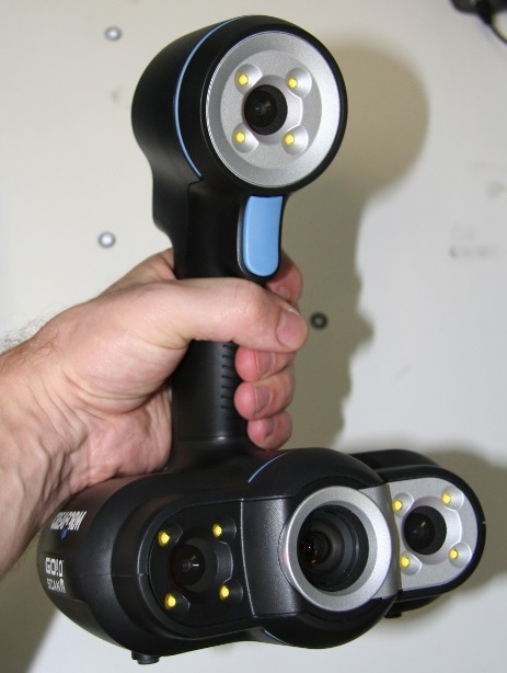
Under the cutter is the description and test drive of the Creaform HandyScan 700 and a little about 2 other scanners and one eye about Surphaser. As well as examples of the use of the scanner in the oil and space industries, medicine and reverse engineering.
Stages of creating a 3d model using a scanner
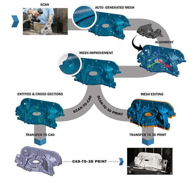
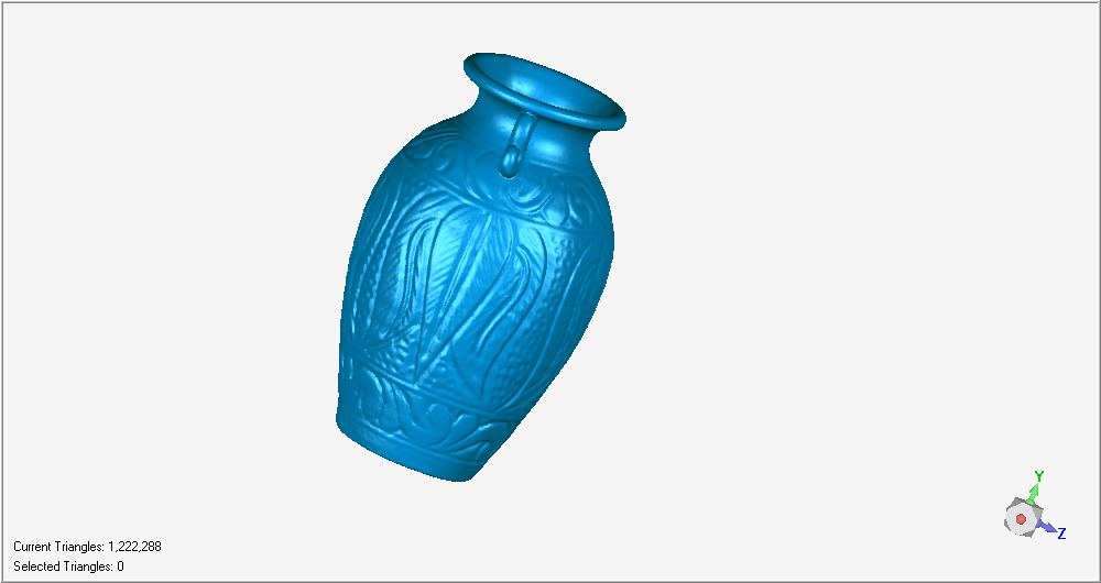
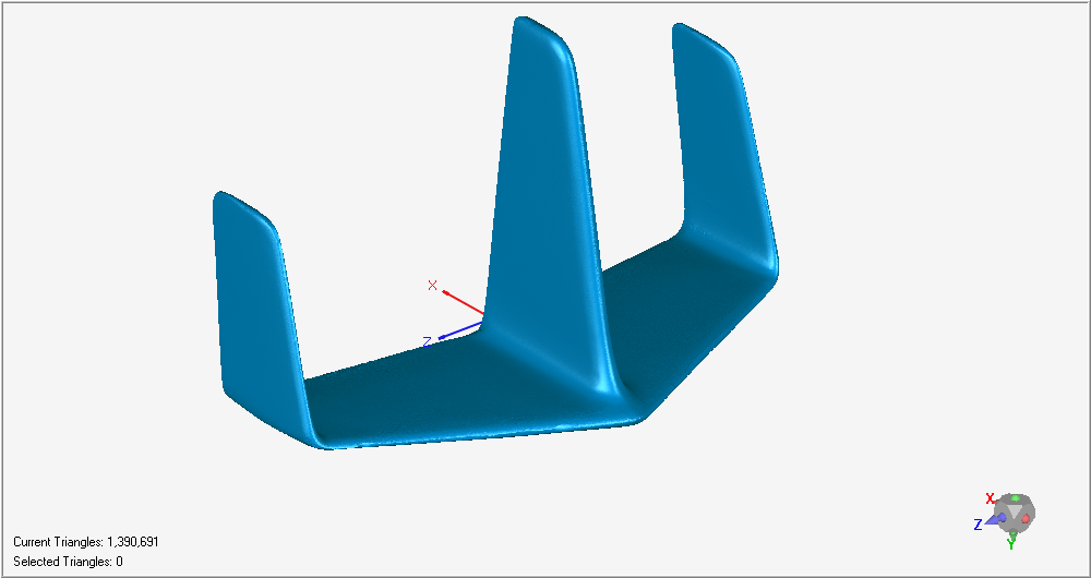
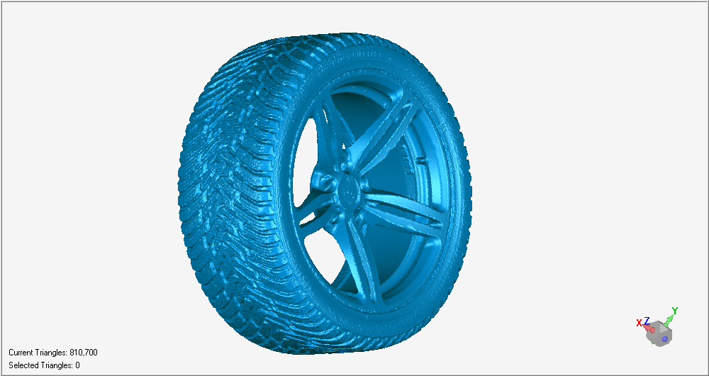
3D scanning is a tool for quickly obtaining the geometry of a three-dimensional object of almost any complexity. However, it must be remembered that the 3D scanner gives a cloud of points in three-dimensional space, located in the shape of an object or a polygonal model - the same points, but connected by lines so that a lot of intersecting planes are obtained that describe the geometry of the object.
Very few people need the geometry of the object, because often the goal of 3D scanning is to obtain accurate drawings of the scanned object, and not just coordinates in three-dimensional space.
But this issue has long been resolved: there is specially software on the market, such as Geomagic DesignX, which allows you to turn a point cloud into a parametric model and transfer it to absolutely any CAD system.
That is, with this software we remove any restrictions at all: scan an object with a 3D scanner, parameterize it in special software, transfer the resulting parametric or NURBS surfaces (whatever) to your CAD and easily work on an editable model, receiving drawings any section in the format we need.
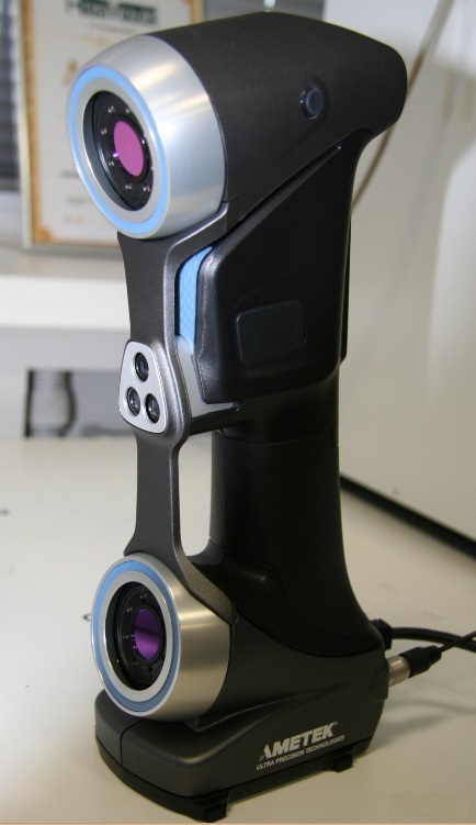
Weight - 122 x 77 x 294 mm
Dimensions 150 x 171 x 251 mm
Measurement speed - 480 000 measurements per second
Scanning area - 275 x 250 mm
Light source - 7 laser crosses (+1 additional line)
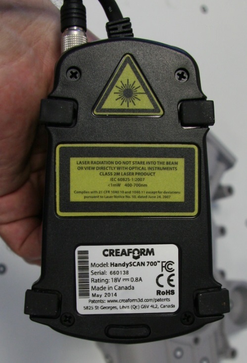
Laser class - II (safe for the eyes )
Resolution 0.05 mm
Accuracy - up to 0.03 mm
Volume accuracy - 0.02 mm + 0.06 mm / m
Distance to the object during scanning - 300 mm
Depth of field - 250 mm
Lens size range (recommended) - 0.1 - 4 m
software - VXelements
Output formats - .dae, .fbx, .ma, .obj, .ply, .stl, .txt, .wrl, .x3d, .x3dz, .zpr
Compatible software - 3D Systems (Geomagic® Solutions), InnovMetric Software (PolyWorks), Dassault Systèmes (CATIA V5 and SolidWorks), PTC (Pro / ENGINEER), Siemens (NX and Solid Edge), Autodesk (Inventor, Alias, 3ds Max, Maya, Softimage).
Connection standard - 1 x USB 3.0
Operating temperature range - 15-40 ° C
Operating humidity range (non-condensing) 10-90%
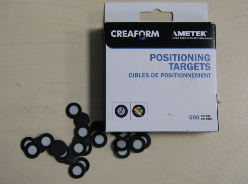
500black marks
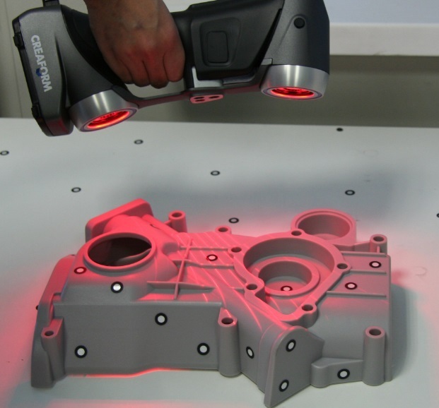
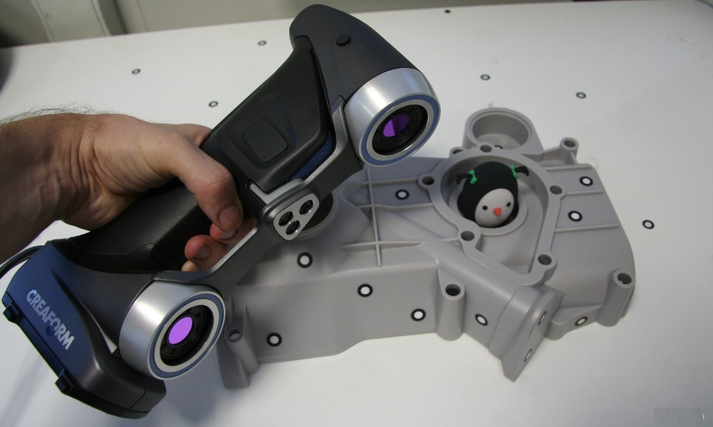
The device itself determines the position. There is no need to use a coordinate measuring machine (CMM), measuring arm or other external positioning device.
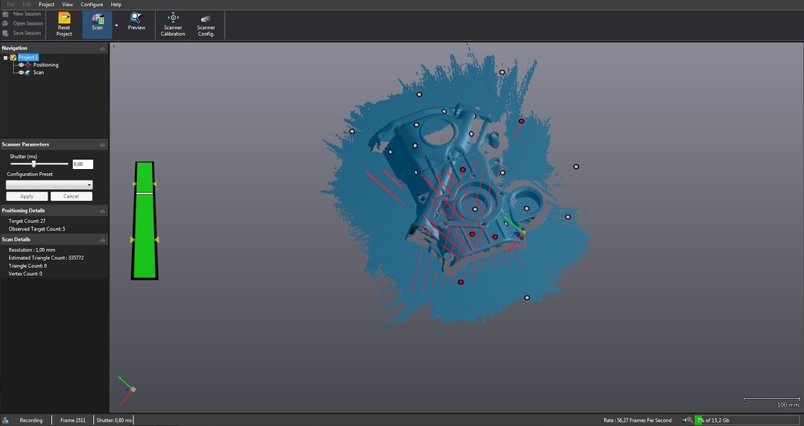
Visualization of the scanned surface in real time.
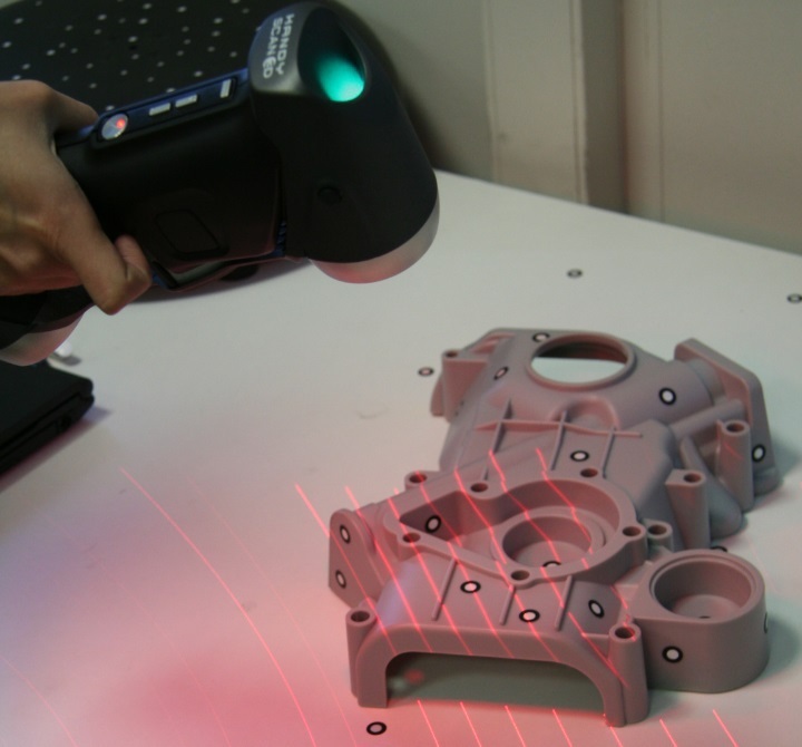
Thanks to dynamic snapping, the object can be moved during three-dimensional scanning, which eliminates the need for a rigid installation.

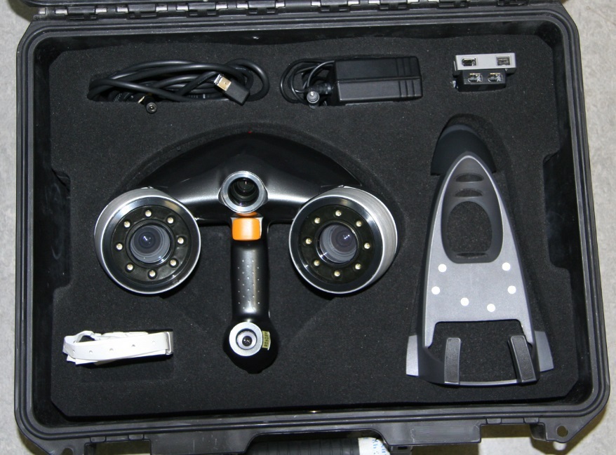
Individual calibration table
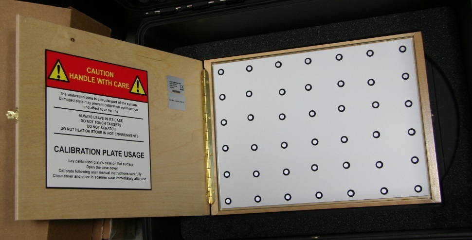
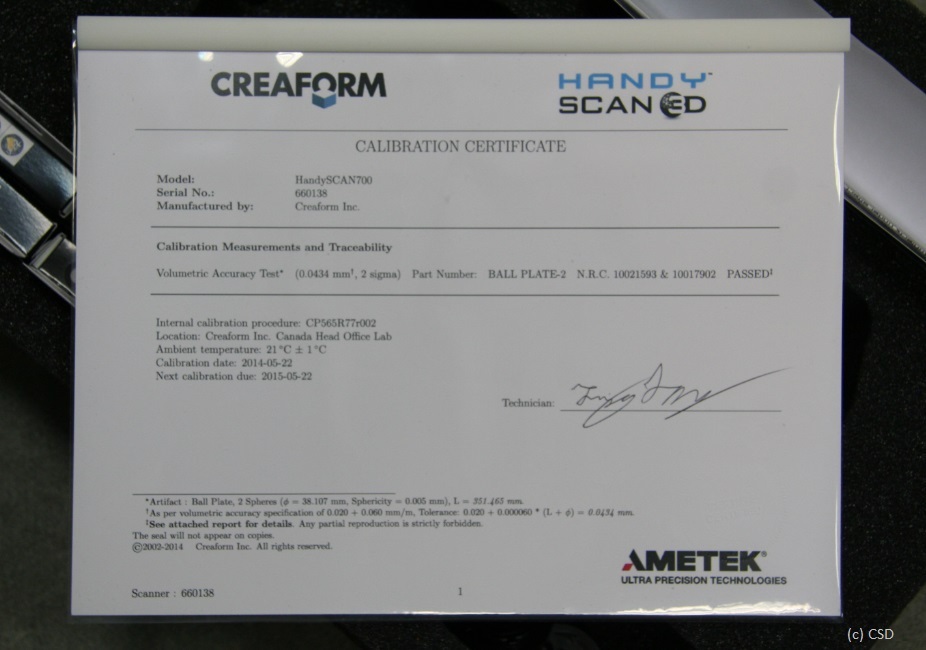
Certificate confirming quality and accuracy
Examples

“At the moment, three-dimensional scanning is used not only to obtain digitized models of various parts, figurines, car bodies, etc. 3D scanning is also widely used in scanning people, and recently this is a particularly requested technology, because it’s interesting to store not only family photos in frames on the bedside table, but also, for example, the whole family, printed on a 3D printer. In addition to entertainment purposes, three-dimensional technologies are increasingly used in medicine. For example, scanning a person’s leg to create a convenient prosthesis, scanning a cast of the patient’s jaw for further work in specialized dental software, scanning organs of a person ... As it might seem at first glance, at present 3D technologies are entertaining in nature, but this has long been not this way.Aleksey, Consistent Software Distribution Specialist
Harsh techies inspect pipeline
GoScan

EXAscan (~ 3 million rubles)
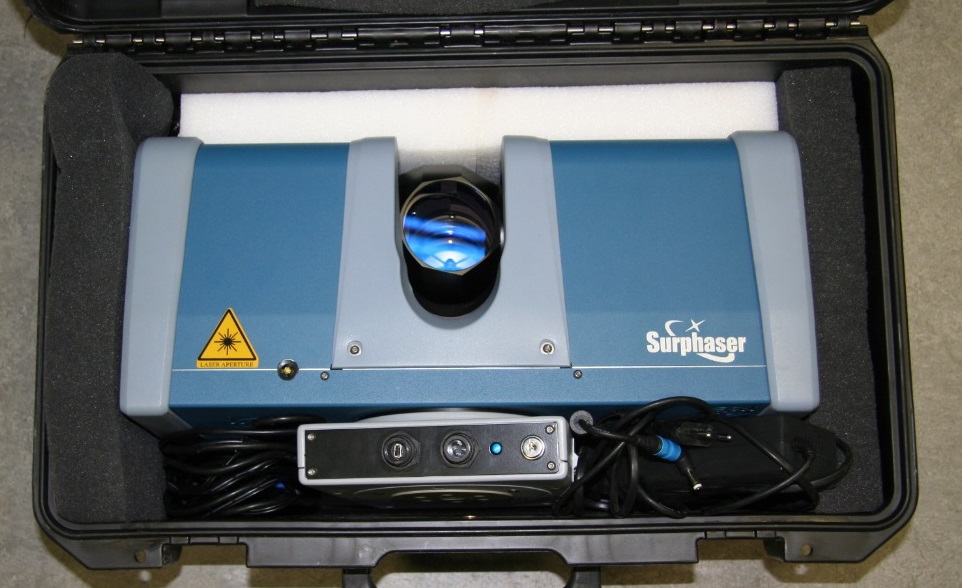
Surphaser (~ 3 million rubles)
Boss
It is used for scanning spacecraft and in the construction of the subway and the military for their own purposes.
Maintenance and repair is carried out in Russia. Surphaser 3D scanners are going to Russia
About this thing is worth writing a separate article.
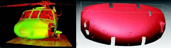
Scanning time: from the bow - 1.5 hours; from the tail - 1 hour
Used software: Cyclone for cleaning and recording data, RapidForm for modeling
Processing time: 10 hours from the formation of a point cloud to the creation of three-dimensional surface models.
Total time: 30 hours from the start of the project to the flight with the new integrated product.
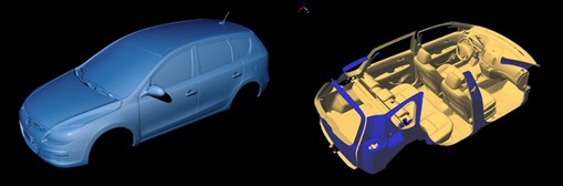
Scanning time: 2 hours
Processing time using PolyWork software for stitching and creating a multi-faceted model: 4 hours
Layout: 15 scans, 90 million dots
Scanning time: 4 hours
Processing time using PolyWork software for aligning and creating a multi-faceted model: 6 hours
Three-dimensional or 3D scanning is the process of converting the physical form of a real object, product into digital form, that is, obtaining a three-dimensional computer model (3d model) of the object.
3D scanning can be useful in solving the problems of reengineering, designing fixtures, accessories, spare parts in the absence of original computer documentation for the product, and also if it is necessary to digitalize surfaces of complex shapes, including art forms and casts.
The operation of the scanner is somewhat reminiscent of a person’s surround vision. As the brain builds a three-dimensional image of what it sees, a 3D scanner receives information by comparing two images that are offset from each other. To achieve the necessary accuracy of building the model, additional technological methods are applied in the form of laser illumination or periodic flash.
Under the cutter is the description and test drive of the Creaform HandyScan 700 and a little about 2 other scanners and one eye about Surphaser. As well as examples of the use of the scanner in the oil and space industries, medicine and reverse engineering.
Stages of creating a 3d model using a scanner
3D scanning is a tool for quickly obtaining the geometry of a three-dimensional object of almost any complexity. However, it must be remembered that the 3D scanner gives a cloud of points in three-dimensional space, located in the shape of an object or a polygonal model - the same points, but connected by lines so that a lot of intersecting planes are obtained that describe the geometry of the object.
Very few people need the geometry of the object, because often the goal of 3D scanning is to obtain accurate drawings of the scanned object, and not just coordinates in three-dimensional space.
But this issue has long been resolved: there is specially software on the market, such as Geomagic DesignX, which allows you to turn a point cloud into a parametric model and transfer it to absolutely any CAD system.
That is, with this software we remove any restrictions at all: scan an object with a 3D scanner, parameterize it in special software, transfer the resulting parametric or NURBS surfaces (whatever) to your CAD and easily work on an editable model, receiving drawings any section in the format we need.
Areas of application for 3D scanners
- Automotive industry
- Transport (buses, trucks, trains)
- Heavy equipment (agricultural technology, excavators, mine equipment)
- Sport, hobbies (ATV (ATV), mototechnics, water transport)
- Aerospace technology
- Consumer goods
- Production - Metal
- Production - Plastic and Composites
- Army, Defense, Government
- Power generation (wind, hydro, atomic)
- Shipbuilding
- Gas and gas
- Education
- Healthcare
- Entertainment and multimedia
- Museology, preservation of heritage
- Architecture, construction, engineering
TTX
Weight - 122 x 77 x 294 mm
Dimensions 150 x 171 x 251 mm
Measurement speed - 480 000 measurements per second
Scanning area - 275 x 250 mm
Light source - 7 laser crosses (+1 additional line)
Laser class - II (safe for the eyes )
Resolution 0.05 mm
Accuracy - up to 0.03 mm
Volume accuracy - 0.02 mm + 0.06 mm / m
Distance to the object during scanning - 300 mm
Depth of field - 250 mm
Lens size range (recommended) - 0.1 - 4 m
software - VXelements
Output formats - .dae, .fbx, .ma, .obj, .ply, .stl, .txt, .wrl, .x3d, .x3dz, .zpr
Compatible software - 3D Systems (Geomagic® Solutions), InnovMetric Software (PolyWorks), Dassault Systèmes (CATIA V5 and SolidWorks), PTC (Pro / ENGINEER), Siemens (NX and Solid Edge), Autodesk (Inventor, Alias, 3ds Max, Maya, Softimage).
Connection standard - 1 x USB 3.0
Operating temperature range - 15-40 ° C
Operating humidity range (non-condensing) 10-90%
500
If you really need to, I do even like this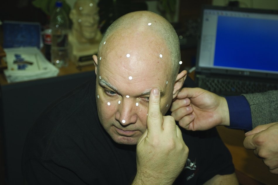
The device itself determines the position. There is no need to use a coordinate measuring machine (CMM), measuring arm or other external positioning device.
Visualization of the scanned surface in real time.
Thanks to dynamic snapping, the object can be moved during three-dimensional scanning, which eliminates the need for a rigid installation.
Individual calibration table
Certificate confirming quality and accuracy
Examples
Application
“At the moment, three-dimensional scanning is used not only to obtain digitized models of various parts, figurines, car bodies, etc. 3D scanning is also widely used in scanning people, and recently this is a particularly requested technology, because it’s interesting to store not only family photos in frames on the bedside table, but also, for example, the whole family, printed on a 3D printer. In addition to entertainment purposes, three-dimensional technologies are increasingly used in medicine. For example, scanning a person’s leg to create a convenient prosthesis, scanning a cast of the patient’s jaw for further work in specialized dental software, scanning organs of a person ... As it might seem at first glance, at present 3D technologies are entertaining in nature, but this has long been not this way.Aleksey, Consistent Software Distribution Specialist
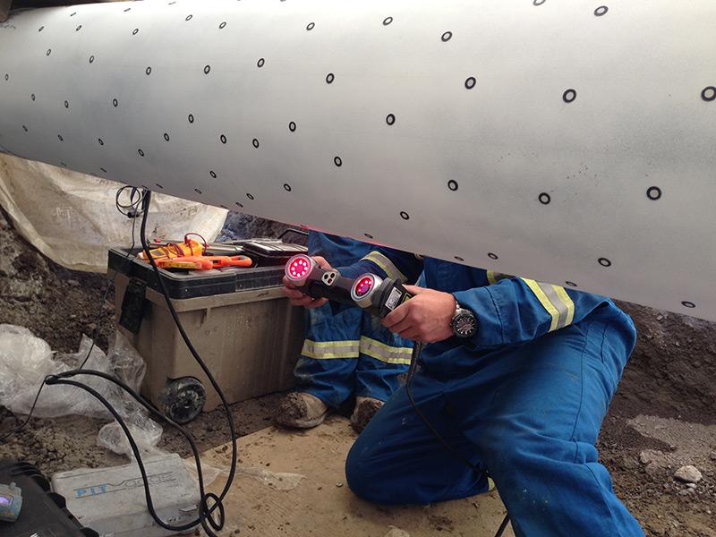
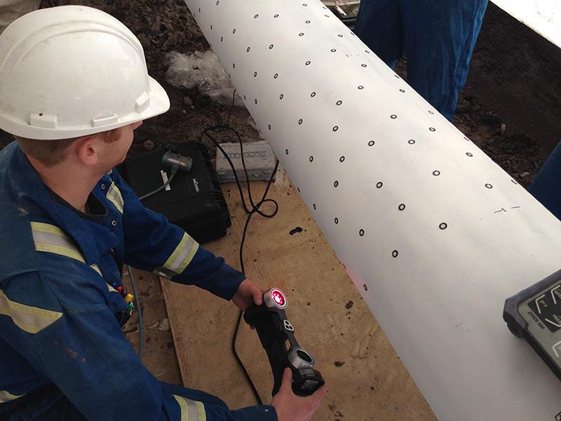
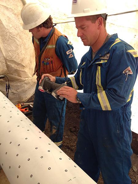
Harsh techies inspect pipeline
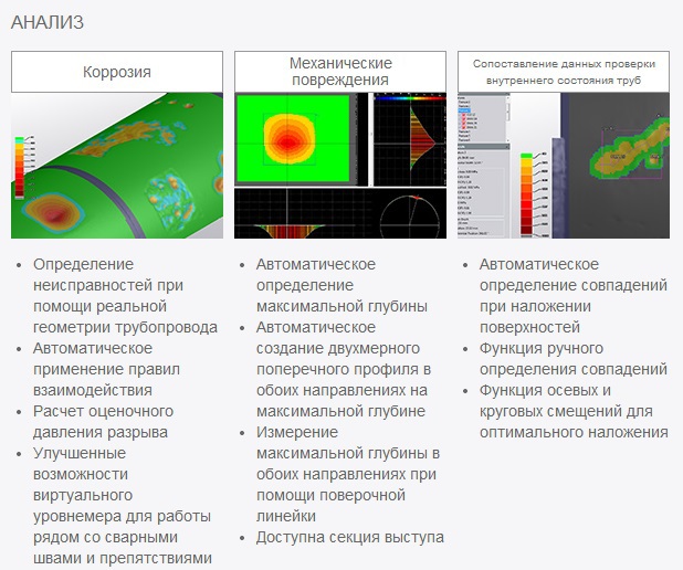
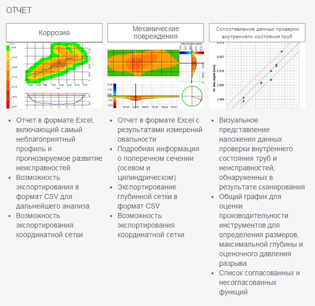
pipeline integrity assessment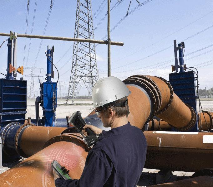
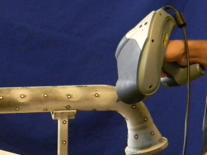
damage assessment of aircraft
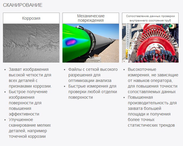
The effect of hail damage on the aerodynamic properties of an airplane is a difficult factor to evaluate, but at the same time, literally, is vital! - make this assessment as accurate as possible. The shape and size of the defects can vary depending on the force of the barrage into which the plane lands. Therefore, the most common way to analyze damage is by measuring the geometry (length, width, and depth) of each dent in the area of the aircraft surface under consideration. There is also a need to control the geometry of parts on the production line.
checking the internal condition of the pipes
Pipeline operators are always torn between ensuring public safety and the economic consequences of excavation in areas where, as it turns out in the future, repairs are not required. Direct assessment methods are used to confirm the measurement results obtained using tools to check the internal state of the pipes. These tools are not always accurate and sometimes require re-calibration. Service companies spend a lot of time comparing data from equipment suppliers to check the internal condition of pipes and data obtained using a level gauge (or any other tool for direct assessment) to evaluate the performance of the tool.
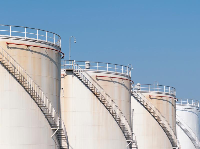
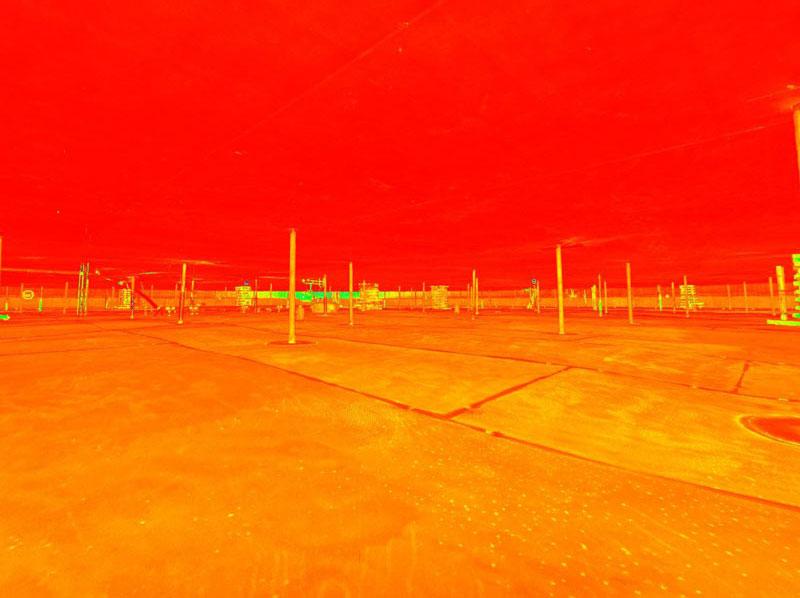
inspection and measurement of tanks
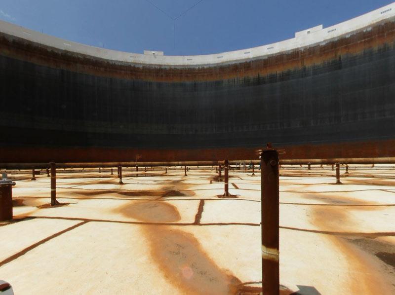
Public concern over environmental issues is forcing oil companies to improve safety practices in relation to environmental protection and health. Inspecting tanks has traditionally been a lengthy process, but now companies can satisfy the public interest thanks to three-dimensional scanning technology, which can improve the accuracy and efficiency of this work. The same tool can be used for other purposes, for example, for measuring tanks. In fact, building an accurate capacity table is one of the industry’s key requirements ...
The tank inspection reports generated by Creaform systems contain important information - such as bottom profiles, vertical profiles, and circular diagrams - necessary to evaluate tank settling.
Capacity calibration tables are used to determine the amount of product in the tank. The report form can be changed in accordance with the needs of the client. The data in the report may or may not include the volume of the internal structures of the tank, the effect on the parameters of the floating roof of the tank, etc.

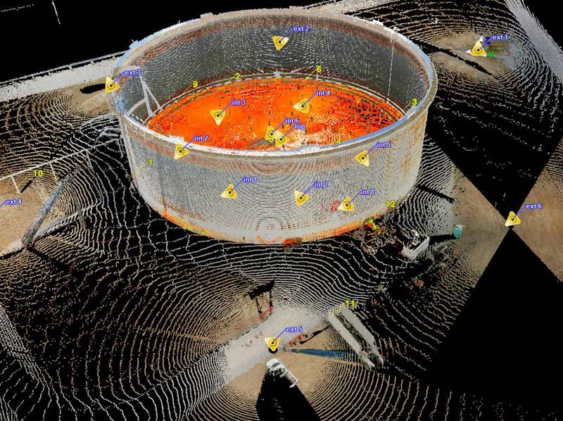
Tank installation
The tank inspection reports generated by Creaform systems contain important information - such as bottom profiles, vertical profiles, and circular diagrams - necessary to evaluate tank settling.
Building capacity calibration tables
Capacity calibration tables are used to determine the amount of product in the tank. The report form can be changed in accordance with the needs of the client. The data in the report may or may not include the volume of the internal structures of the tank, the effect on the parameters of the floating roof of the tank, etc.
3d modeling for phased array control
for the aerospace industry
Service aircraft and their components and structures must be monitored and evaluated for the level of degradation and remaining service life. Aircraft designers and air carriers are faced with the problem of controlling complex components (for example, gas turbines, engine compartments, fairings, cockpit, etc.), which are parts of very complex components and cannot be removed for inspection. To solve this problem, they usually turn to phased array control.
Modeling the focal law of the phased array is used to predict the results of control and optimize the configuration of the sensor and wedge. Controlling components of complex shape using a two-dimensional matrix can be challenging. For lack of a better solution, the 3D model is usually taken from a CAD file or from a theoretical design model. However, the actual shape of the component differs from the ideal theoretical model and, therefore, the accuracy of ultrasound scanning and the probability of detection are impaired.
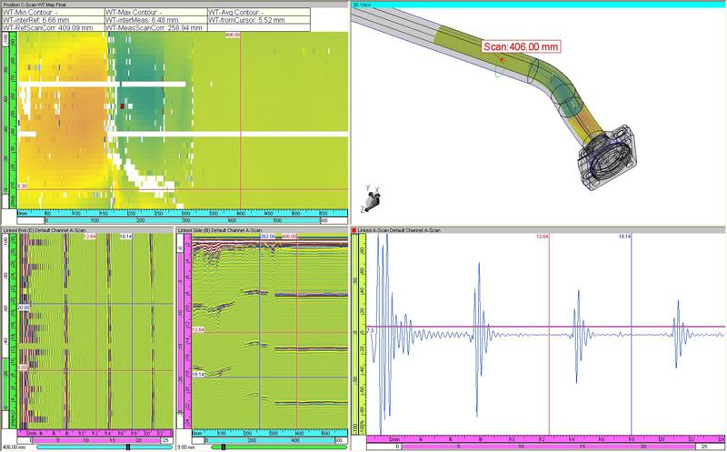
Modeling the focal law of the phased array is used to predict the results of control and optimize the configuration of the sensor and wedge. Controlling components of complex shape using a two-dimensional matrix can be challenging. For lack of a better solution, the 3D model is usually taken from a CAD file or from a theoretical design model. However, the actual shape of the component differs from the ideal theoretical model and, therefore, the accuracy of ultrasound scanning and the probability of detection are impaired.
for energy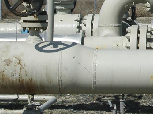
The components and designs of power plants need to be monitored and evaluated for the level of degradation and remaining service life. Energy companies face the challenge of controlling complex components (dovetail parts, nozzles, feed tubes, etc.) that are part of very complex assemblies and cannot be removed for inspection. To solve this problem, they usually turn to phased array control.
Modeling the focal law of the phased array is widely used, especially in the nuclear industry, to predict the results of monitoring and optimize the configuration of the sensor and wedge. Controlling components of complex shape using a two-dimensional matrix can be challenging. For lack of a better solution, the 3D model is usually taken from a CAD file or from a theoretical design model. However, the actual shape of the component differs from the ideal theoretical model and, therefore, the accuracy of ultrasound scanning and the probability of detection are impaired.
Other models
GoScan
EXAscan (~ 3 million rubles)
Surphaser (~ 3 million rubles)
Boss
It is used for scanning spacecraft and in the construction of the subway and the military for their own purposes.
Maintenance and repair is carried out in Russia. Surphaser 3D scanners are going to Russia
About this thing is worth writing a separate article.
Scanning time: from the bow - 1.5 hours; from the tail - 1 hour
Used software: Cyclone for cleaning and recording data, RapidForm for modeling
Processing time: 10 hours from the formation of a point cloud to the creation of three-dimensional surface models.
Total time: 30 hours from the start of the project to the flight with the new integrated product.
Scanning time: 2 hours
Processing time using PolyWork software for stitching and creating a multi-faceted model: 4 hours
Layout: 15 scans, 90 million dots
Scanning time: 4 hours
Processing time using PolyWork software for aligning and creating a multi-faceted model: 6 hours