A fairly simple and effective algorithm for recognizing and tracking movement
After honoring an article on the site by Alexander Shuravin (megabax) with the title: “A simple motion recognition algorithm”, there was a need to advance in solving the problem posed in the article. As a result, an algorithm has appeared for processing a sequence of frames containing displays of moving objects, for example, vehicles (TS).
At the output of the algorithm, several frames are formed - according to the number of vehicles displayed in the input sequence. Each output frame displays an individual track of the vehicle in the field of view of the camera and an image of this vehicle. Digital information about the current position of the center of the bordering rectangle, instantaneous and average vehicle speed will be placed there.
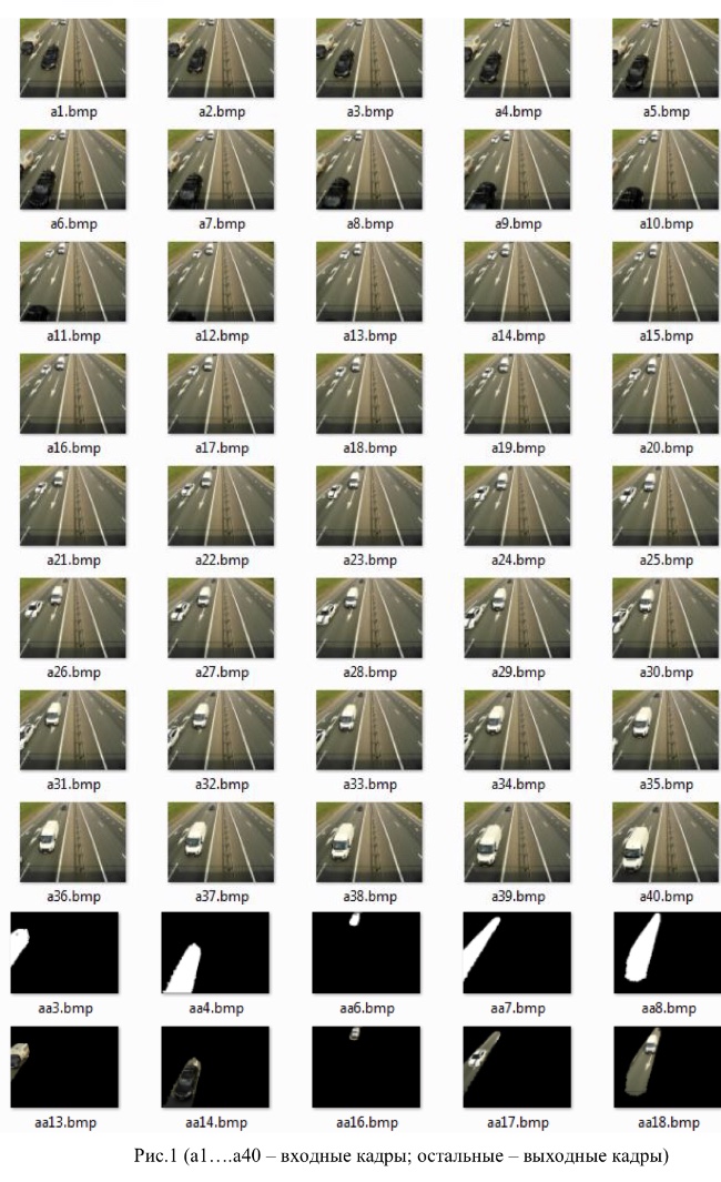
For example, Figure 1 shows the results of processing the input sequence, consisting of 40 frames, taken from one of the overpasses over the M8 highway. Five frames were formed at the output with the display of the track and the image of each vehicle that fell within the camera’s field of view.
The algorithm consists of three blocks.
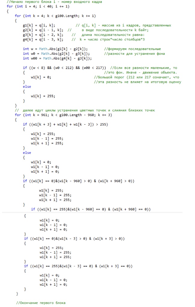
In the first block, a binary frame is formed from several consecutive frames, which displays moving objects and / or their fragments in the form of white spots on a black background.
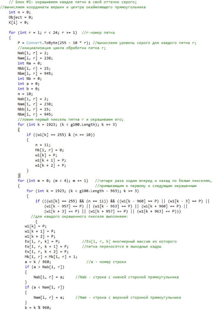
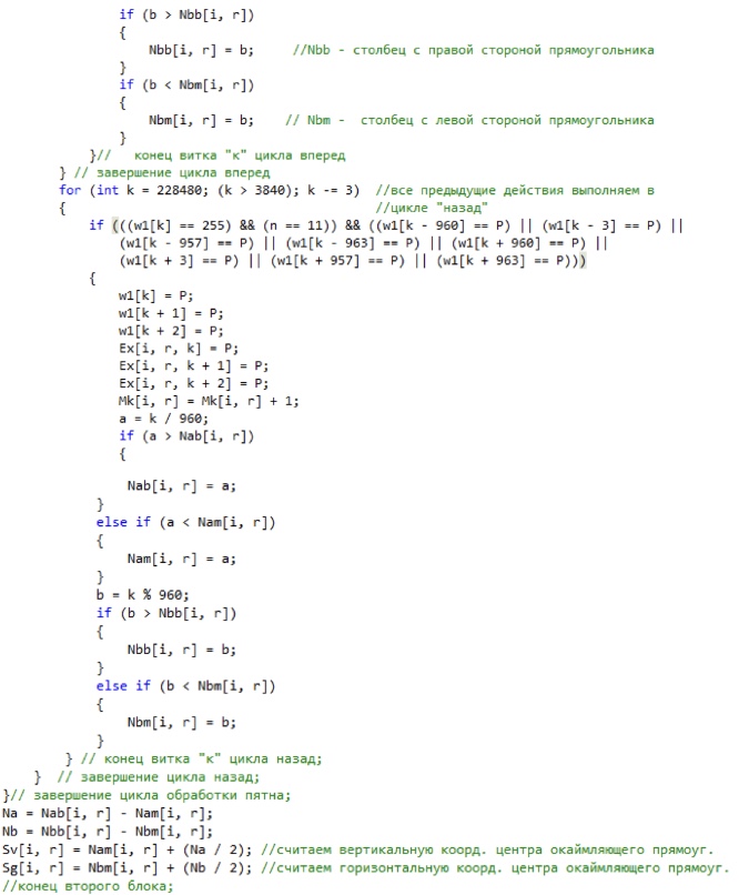
In the second block, each spot is colored in its own shade of gray and the mass of pixels in the spot, the sizes of the rectangle bordering the spot, and the coordinates of its vertices and center are calculated.
In the third block, the displacement of each spot relative to each spot in the previous frame is calculated, and the spot that is most likely related to the same object is determined by the minimum displacement. Due to the individual coloring, these spots can be distinguished and transferred to separate frames, displaying a sequence of close spots.
Such frames are individual for each spot and ultimately display the track of a moving object formed by the imposition of synchronously moving spots. Vehicle speed can be estimated by shifting the center or vertices of the rectangles bordering the spot. A more accurate method is described in the article [1].
The algorithm is quite effective, thanks to the information content of the output frames. They can contain digital information about the position and speed of the vehicle in the field of view of the camera, as well as visual data on the size, appearance of each vehicle and its track.
Here is a screenshot of the program for the first and second blocks.
The code of the third block contains many of the same sorting and turned out to be rather difficult and slow. Therefore, it is not given in the article. I can send the complete code of the processing program to those who wish. (It is necessary, however, to understand that the program is written by a "teapot").
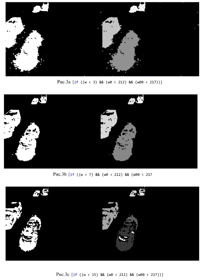
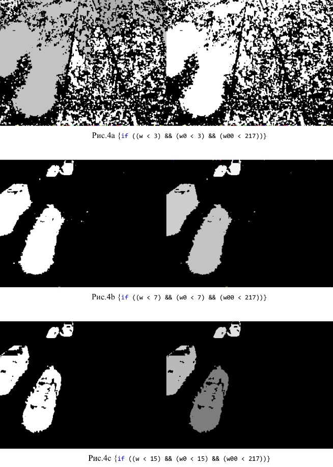
To configure the algorithm, you need to set thresholds for estimating the value of pairwise comparison of the level of illumination in the same pixels of adjacent frames. The optimal thresholds correspond to the minimum number of spots on a binary frame indicated in the program by the symbol w1 [k].
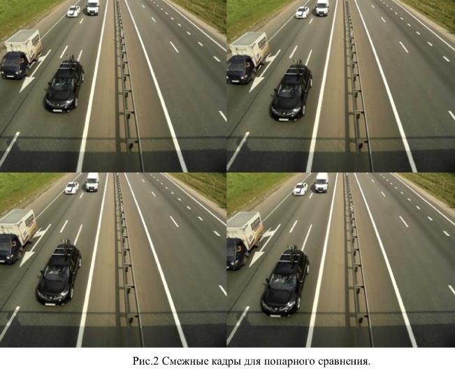
Figure 2 shows a group of frames for pairwise comparison of illumination in each pixel.
Figures 3a, 3b, 3c show the influence of the threshold value on the appearance of a binary frame and a grayscale frame obtained from two adjacent frames (the second and third thresholds are so large that they disable the third and fourth frames).
Figures 4a, 4b, 4c show the effect of the threshold on the appearance of the binary frame and the grayscale frame obtained from three adjacent frames (the third threshold disables the fourth frame).
Figures 5a, 5b, 5c show the effect of the threshold value on the appearance of a binary frame and a frame in shades of gray obtained from four adjacent frames.
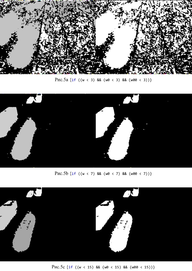
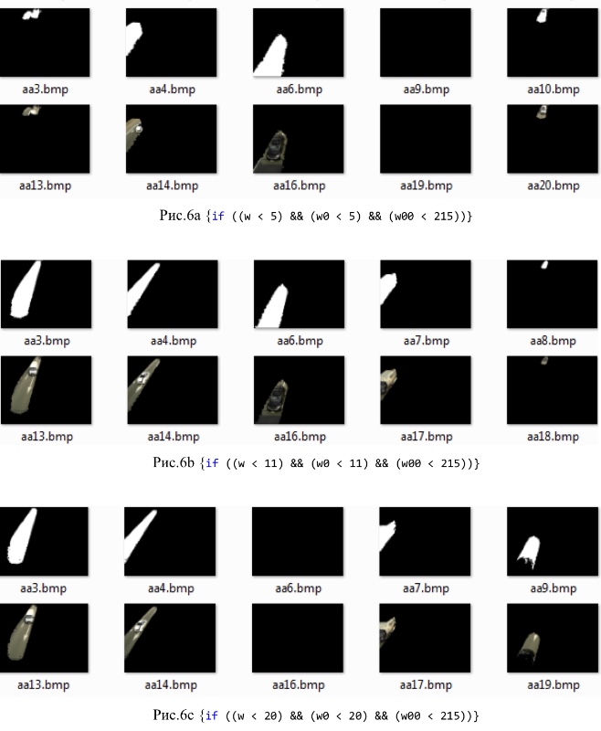
Fig. 6 shows the influence of the threshold value on the type of output frames.
Literature
1. Yakovlev A.A. Determination of speed by video using the method of singular points. Actual issues of modern science / Collection of articles on the materials of the 1X international scientific and practical conference (February 8, 2018, Tomsk). Part 1 .- p. 97 / - Ufa: Ed. Dendra, 2018.
At the output of the algorithm, several frames are formed - according to the number of vehicles displayed in the input sequence. Each output frame displays an individual track of the vehicle in the field of view of the camera and an image of this vehicle. Digital information about the current position of the center of the bordering rectangle, instantaneous and average vehicle speed will be placed there.
For example, Figure 1 shows the results of processing the input sequence, consisting of 40 frames, taken from one of the overpasses over the M8 highway. Five frames were formed at the output with the display of the track and the image of each vehicle that fell within the camera’s field of view.
The algorithm consists of three blocks.
In the first block, a binary frame is formed from several consecutive frames, which displays moving objects and / or their fragments in the form of white spots on a black background.
In the second block, each spot is colored in its own shade of gray and the mass of pixels in the spot, the sizes of the rectangle bordering the spot, and the coordinates of its vertices and center are calculated.
In the third block, the displacement of each spot relative to each spot in the previous frame is calculated, and the spot that is most likely related to the same object is determined by the minimum displacement. Due to the individual coloring, these spots can be distinguished and transferred to separate frames, displaying a sequence of close spots.
Such frames are individual for each spot and ultimately display the track of a moving object formed by the imposition of synchronously moving spots. Vehicle speed can be estimated by shifting the center or vertices of the rectangles bordering the spot. A more accurate method is described in the article [1].
The algorithm is quite effective, thanks to the information content of the output frames. They can contain digital information about the position and speed of the vehicle in the field of view of the camera, as well as visual data on the size, appearance of each vehicle and its track.
Here is a screenshot of the program for the first and second blocks.
The code of the third block contains many of the same sorting and turned out to be rather difficult and slow. Therefore, it is not given in the article. I can send the complete code of the processing program to those who wish. (It is necessary, however, to understand that the program is written by a "teapot").
To configure the algorithm, you need to set thresholds for estimating the value of pairwise comparison of the level of illumination in the same pixels of adjacent frames. The optimal thresholds correspond to the minimum number of spots on a binary frame indicated in the program by the symbol w1 [k].
Figure 2 shows a group of frames for pairwise comparison of illumination in each pixel.
Figures 3a, 3b, 3c show the influence of the threshold value on the appearance of a binary frame and a grayscale frame obtained from two adjacent frames (the second and third thresholds are so large that they disable the third and fourth frames).
Figures 4a, 4b, 4c show the effect of the threshold on the appearance of the binary frame and the grayscale frame obtained from three adjacent frames (the third threshold disables the fourth frame).
Figures 5a, 5b, 5c show the effect of the threshold value on the appearance of a binary frame and a frame in shades of gray obtained from four adjacent frames.
Fig. 6 shows the influence of the threshold value on the type of output frames.
Literature
1. Yakovlev A.A. Determination of speed by video using the method of singular points. Actual issues of modern science / Collection of articles on the materials of the 1X international scientific and practical conference (February 8, 2018, Tomsk). Part 1 .- p. 97 / - Ufa: Ed. Dendra, 2018.