What does it cost us to build a PCI-E riser
Once upon a time I collected myself a mini-computer . But here's the ill luck - 3D modeling and what a sin to hide - banal toys made this box take a lot of thought, and make me nervous. But you can't just take and connect a video card to it - there is a PCI-E X4 slot, but there is no space in the case. Yes, and nutrition will not be able to provide (if not to talk about quite a very budget plugs). What options to solve this problem are on the market, what they did not suit me and what happened in the end, I will try to describe in this article. I ask under the cat, who is not afraid of a large number of pictures !
Prologue
To connect the video card, a 4-line PCI-E riser with additional power was required with the ability to control it if the power supply was separate. So the usual loop-outs and many are painfully familiar due to mining a riser with a USB cable as an interface cable.
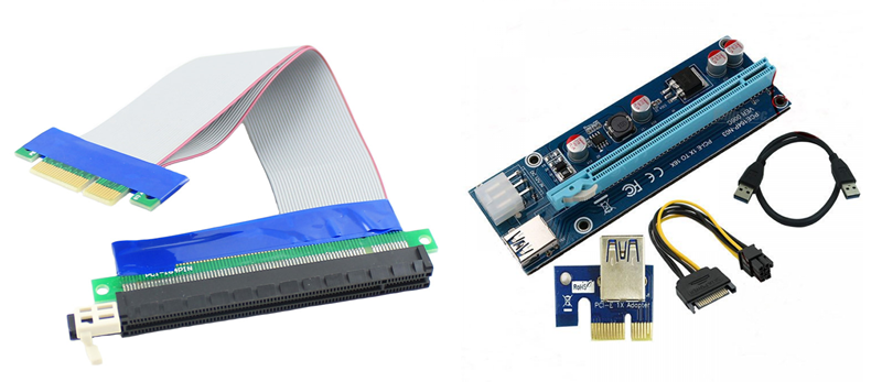
Mass products with mass quality
And here is one of the more or less satisfying my requests can be found in the open spaces of the network:
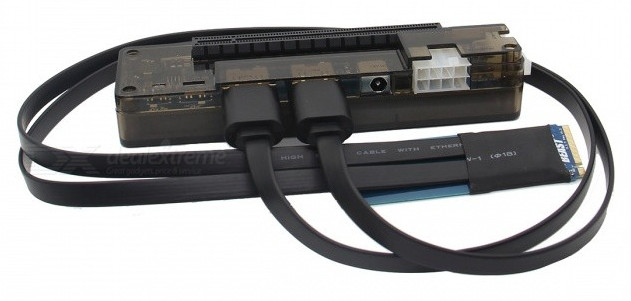
- PE4C V4.1 - first of all, the board installed in the slot obviously did not fit into my PC in terms of dimensions. And the HDMI cables themselves are pretty hard, and there are 2 of them here too! And the price of ~ $ 140 seemed to me not quite humane.

- EXP GDC - there was a version for the pci-e x4 slot, but it also had the inhuman price, 2 previously encountered HDMI cables. Now I can’t even find her picture - it was rarely sold outside of China. But for the pci-e x4 slot, the board is even bigger than the PE4C
Version for M2. And for a regular PCI-E slot, it’s gone
- ADT-Link riser - was not presented at the time of my throwing. And now the information on them is not thick. But it seemed to me
wildlystrange to vary so much the price of the device from the length of the loop.
Not finding a suitable solution for myself, I had to choose from two options - to score or make it myself. It is clear that for the first version the article could have been completed on this, but I will probably continue.
Design
After talking in various communities dedicated to this topic, it was decided to make the riser versatile, not just for yourself - to the laptop (via Mini Pci-E, M2 or even MXM) and to the computer in slot x16 without limitation to only 4 data lines !
Here is a list of requirements that I set for myself:
- Power supply only 12v. 3.3v receive at the riser itself using dc-dc converter.
- Power management, regardless of the type of power supply used (controlled by ATX or normal power supply at 12v)
- Connection of various adapters via detachable cables of the same type (without soldering).
- Split the x16 interface into 4 groups. Thus for the x1-x4 interface - 1 cable, x8 - 2 cables and 4 cables for x16.
- Sometimes I see a situation when a video card connected to a laptop through EXP GDC was fed by a notebook power supply unit to 19v (a plug is present, it is necessary to plug in) prompted to add an indication of the input voltage within acceptable limits: 12v ± 5%.
Implementation
Desires are described, courage has accumulated enough - it's time to embody! Raiser is essentially an extension cord. And the cable is its main part. As such, varieties of LVDS cables were used - the so-called micro coaxial cable assembly. They are often used to connect the matrix displays of various devices.
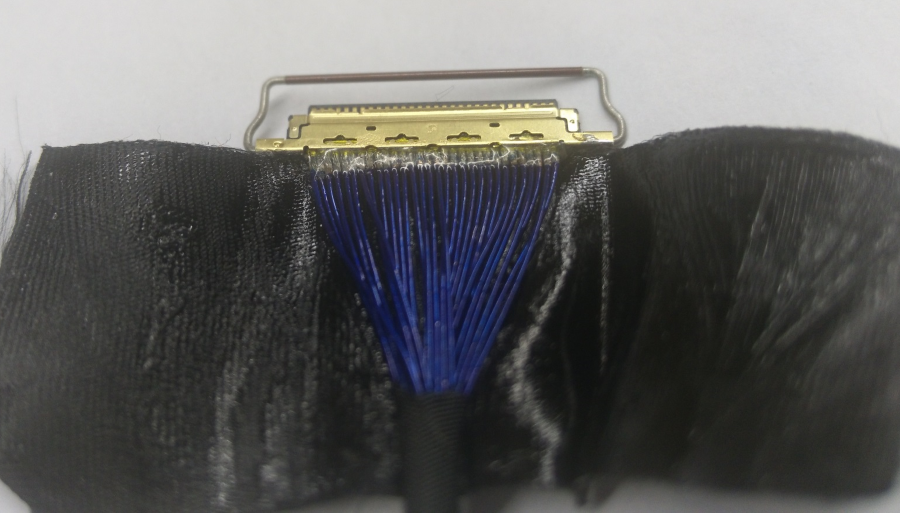
Bare cable 18+
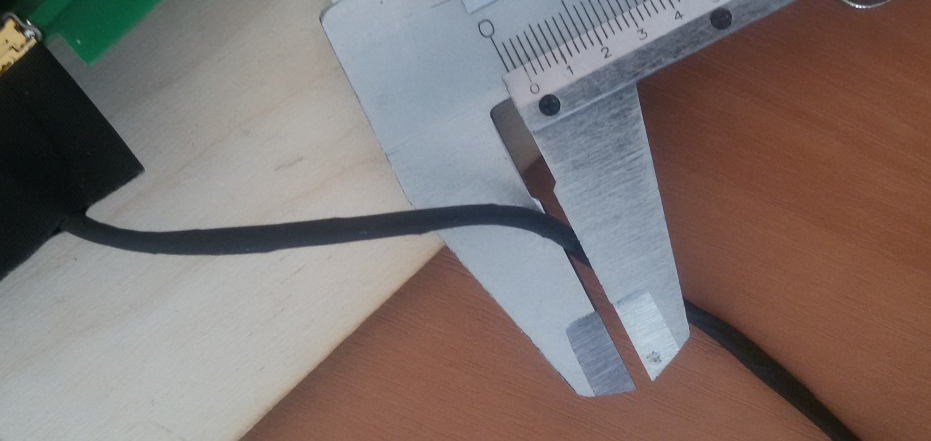
30 lived and only 2mm in diameter.
Although it is extremely difficult to find them in open sale, I managed to find a manufacturer in China ready to make such cables in any quantity (even 1pc) of any length and with a suitable connector.
When the choice of interface cable was finished, I was finally able to work on the design of the riser board and the selection of components. In the end, the designed boards were ordered, the components were purchased and everything was put together:

Top of the board

Bottom of the board
- Power connector 8pin (15A maximum current), combined with a turn-on signal (for ATX power supplies)
- The display of the supply voltage within the allowable limits (+ 12v ± 5%) on the window comparator. Green LED - voltage is normal, red - out of range
- Power management - mosfet in case of using a power source without control and giving a PS ON signal. The control signal is the 3.3v power supply on the host.
- Step-down DC \ DC to get 3.3v
- Cooler connector
- LVDS connectors for interface cables
- PCI-E x16 slot
- Protection against short circuit and over voltage - fuse and TVS diode.
- Connecting additional power video card
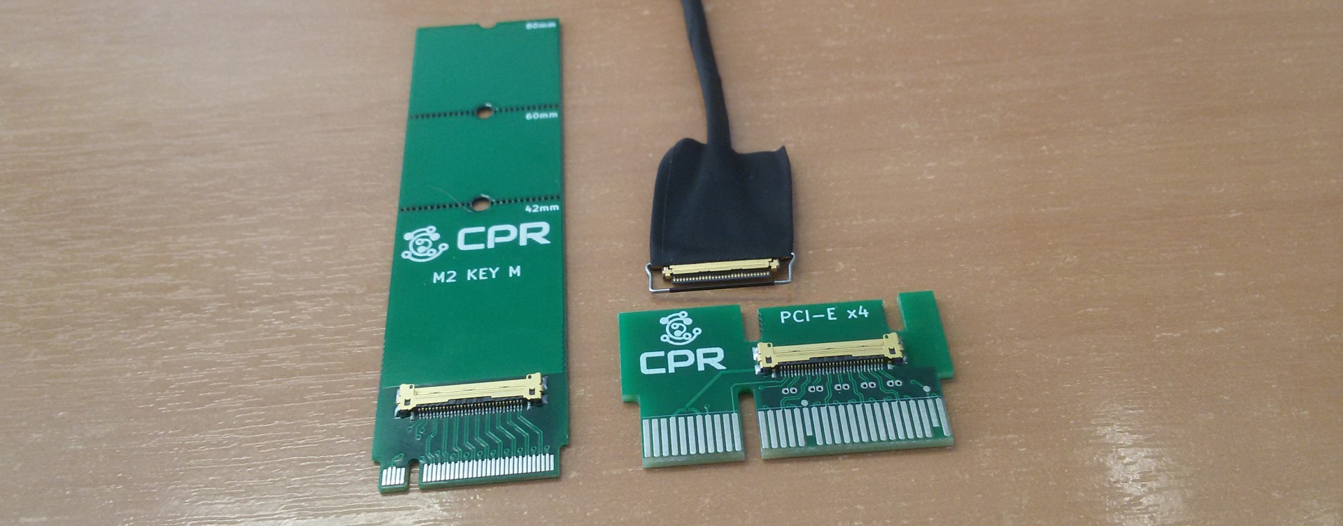
On the other side of the cable, the adapter board for the slot of the end device: The
weighty minus of such a solution (as with analogs) is that you cannot quickly connect / disconnect the riser without having to disassemble a laptop / computer. And the connectors themselves are not intended for external use and have low mechanical strength and low resource. Therefore, in addition I made such an adapter with more reliable connectors (the cable itself with such connectors cannot be made immediately ... for reasonable money):
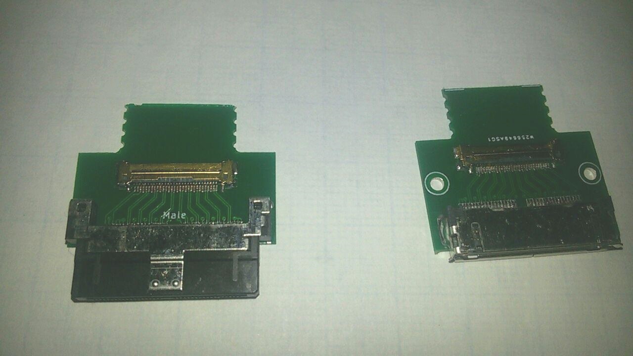
Similar connectors were used in docking stations for smartphones, tablets and other devices

Connecting with 2 cables, and these adapters connect them
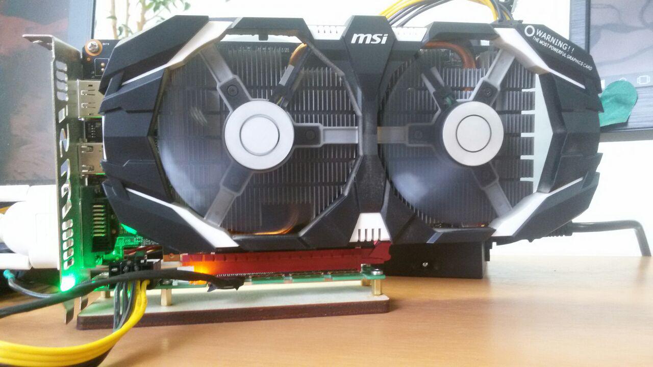
Testing
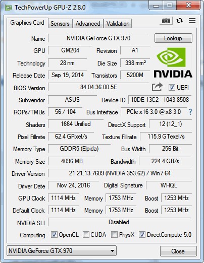
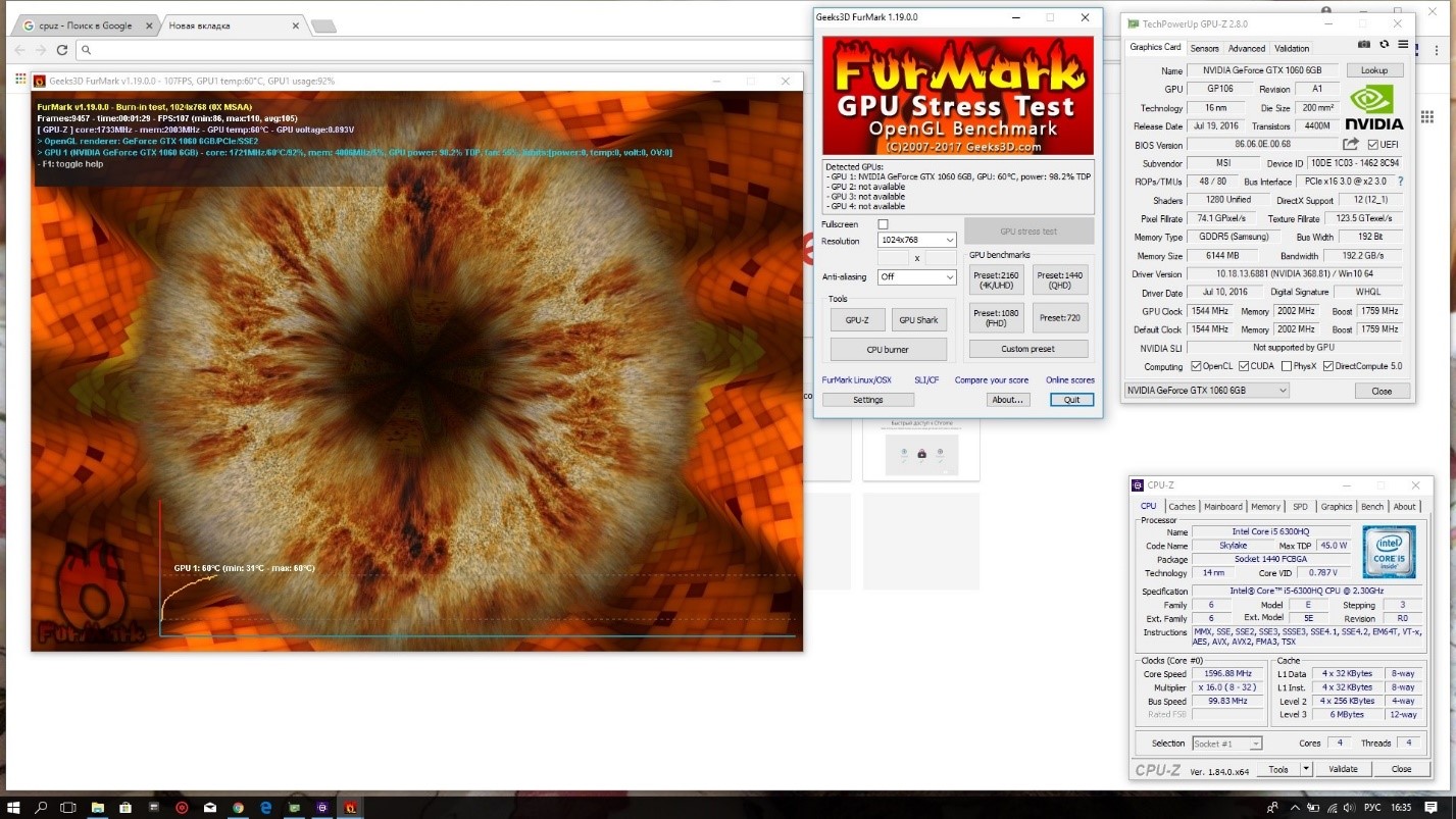
All components on the board are soldered, cables are connected - it's time to cross your fingers and test! The photo is a prototype and has differences from the final version. As they connected with 2 interface cables, they got PCI-E x8. With the passage of various tests, there were no problems and the video card worked stably under load, and the bus frequency increased (gen3) For testing, we managed to get a laptop with an M2 Key M slot with NVME support - MSI GE62 6QD. But for the prototype, an adapter with M + B keys was made for greater versatility, so it is possible to use only 2 lines out of 4 available: Since this was a prototype, the use of electrical tape and the removal of dc / dc on a separate board are quite appropriate. Running a laptop with EGPU. BP starts automatically when you turn on the laptop


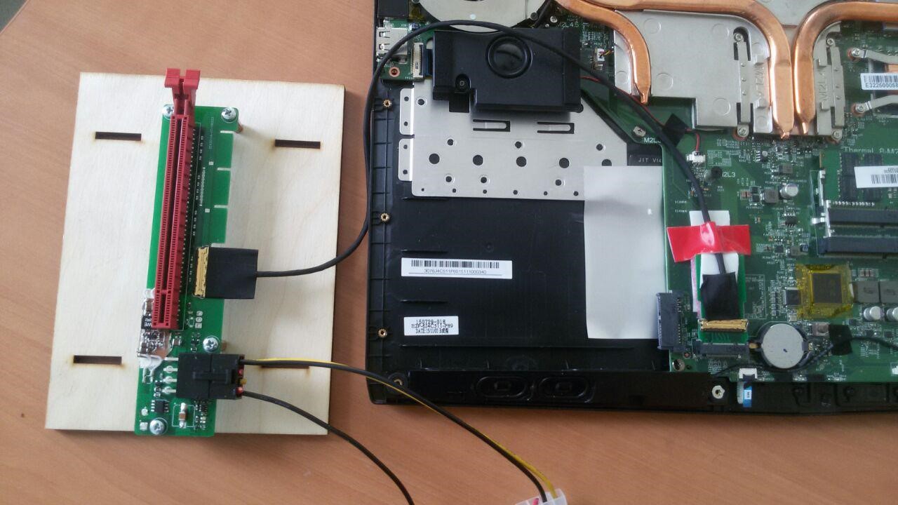


Due to the presence of an integrated and discrete video card in my laptop, I had to tinker with installing drivers. Work under load Unfortunately, these pieces of iron were at my disposal for a very short time and I did not have the opportunity to perform more detailed testing after receiving the final version of the riser. So it was necessary to be content only with such iron:
- Asus Q87T MP
- CPU Core I3 4150T
- RAM 2 * 4GB Crucial DDR3L SO-DIMM PC-12800
- Intel Dual-Band Wireless-AC 7260 Wi-Fi / BT Module
- SSD mSATA 120GB Crucial M500
- HDD 2.5` Seagate Momentus 500GB
- MSI RX 560 4Gb

For the sake of what it all started in reality.
Of course, the configuration is far from productive and to get a significant advantage from connecting via bus x4 instead of x1 did not work in various tests. Often it all came down to a weak iron.

Differences within the
MOBA-type error (WOT, for example) showed indifference to the bus in this configuration - if there is enough video memory, there is no need to load data in closed small locations.
But in online games with an open world, especially in places of mass gathering of players, the difference is quite noticeable. Here are 3 FPS measurements in Black Desert:
| Measuring | min | avg | max |
| pci-e x4 gen1 ≈ pci-e x1 gen3 | |||
| one | five | 28 | 51 |
| 2 | five | 29 | 49 |
| 3 | five | 29 | 51 |
| pci-e x4 gen3 | |||
| one | 7 | 31 | 56 |
| 2 | 6 | thirty | 51 |
| 3 | 7 | 31 | 53 |
Plans and Results
Though the project was started as a universal one and not only for itself, it did not find much popularity. I did not find it at all. Nevertheless, I got what I wanted and invaluable experience and knowledge. As they say a negative result is also a result!
They also often ask me why I did not try to implement the support of the now-fashionable interface Thunderbolt3. The problem is that this interface will require licensing from Intel. And no documentation on the controllers just will not give. There is even a narrow circle of developers of solutions on Thunderbolt3 under the patronage of the same Intel. I was naturally not accepted there.
Although there were rumors that this interface would be open and accessible to everyone, but at the moment it’s just rumors and the standard has remained closed. But I would love to try to develop the project in this direction.
Quite a few questions were about the connection option instead of MXM video cards. There were plans for such an option, but I had to give it up for two reasons - the funds for R & D came to an end and I would have nothing to test on it.
In general, I will be very happy to hear comments and suggestions from swaggers. Thanks for attention!
PS
Since this is generally my first experience in developing an electronic device, I had to turn to more experienced people in this regard, so I want to say a big thank you to NordicEnergy and Paging for advice and answers to my (sometimes stupid) questions!