Unreal Engine Tutorial: Cel Shading
- Transfer
Thanks to physically accurate rendering, Unreal Engine 4 makes it easy to develop realistic games. The rendering model simulates the interaction of light with materials, which leads to the creation of a realistic picture. However, if you want to develop a game with a stylized appearance, then you have to explore other techniques.
One way to create styling is to use cel shading (also known as toon shading). This technique mimics the shading commonly used in cartoons and anime. Examples of its use can be seen in games such as Jet Set Radio , The Legend of Zelda: The Wind Waker, and Gravity Rush .
In this tutorial you will learn the following:
- Create and use post-processing material
- Create cel shader
- Isolate a cel shader for individual meshes
- Manage color bars using lookup tables
Note: This tutorial assumes that you are already familiar with the basics of Unreal Engine. If you are new to the Unreal Engine, then you should first study the ten-part tutorial of the Unreal Engine for beginners .
Getting to work
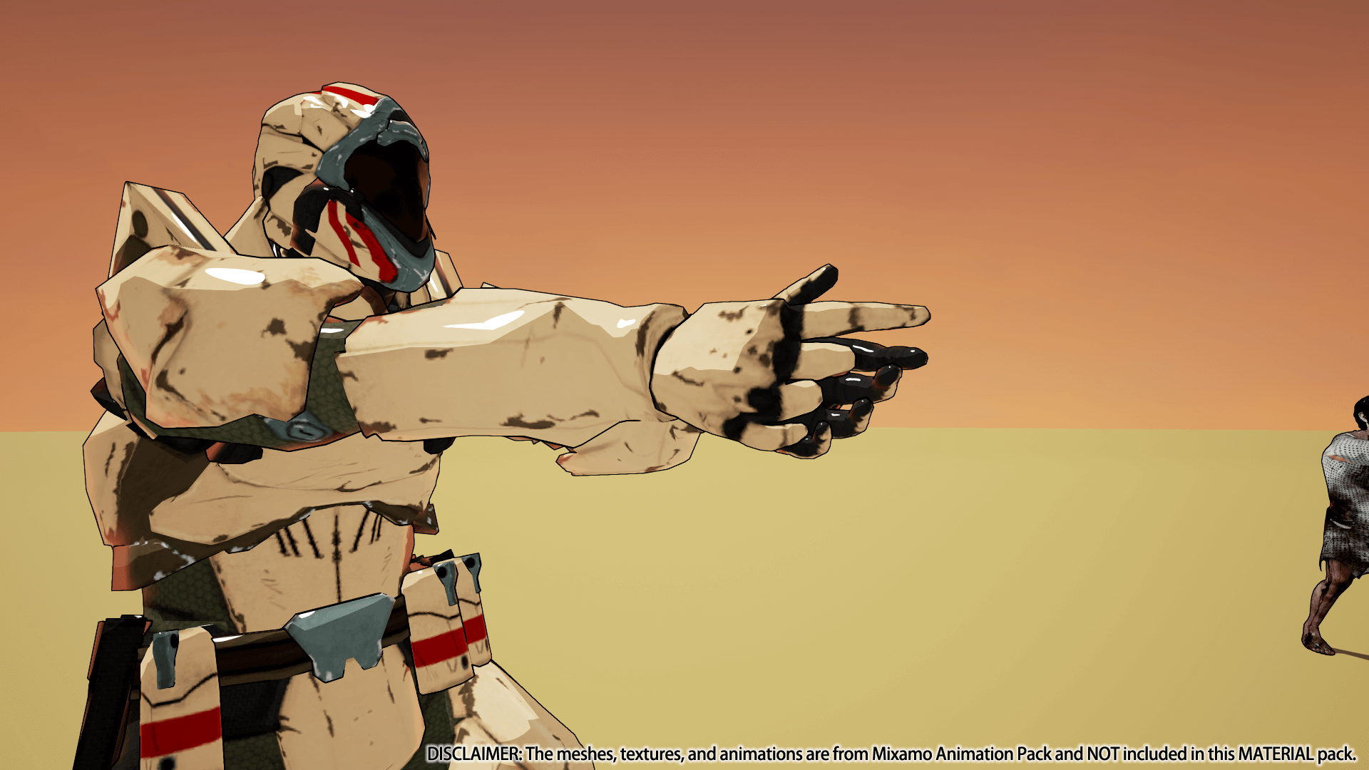
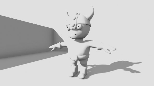
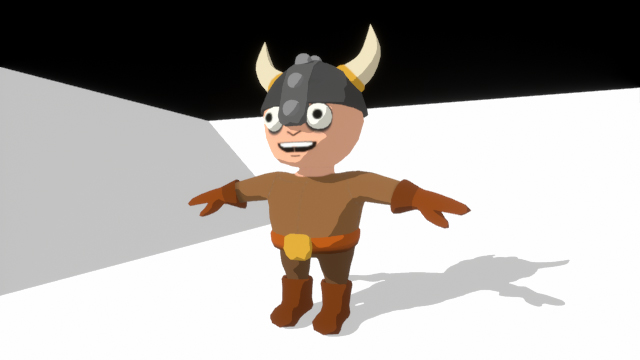
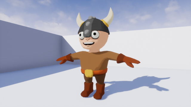
Download the project blank and unzip it. Go to the project folder and open CelShader.uproject . You will see the following scene:
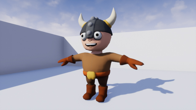
This is the character to whom we will apply cel shading. Before you begin, you need to figure out what cel shading is.
What is Cel Shading?
Cel shading is a rendering process using multiple color streaks rather than a continuous gradient.
Below is an example of using cel shading in The Legend of Zelda: Breath of the Wild . Note that cel shading is implemented only for the character, and the background remains normal.

There are three stripes in this image: one for shadows, one for mid tones, and another for highlights.
It is often mistakenly believed that cel shading is applied if objects have outlines . An example of this is Borderlands . Although this game has a stylized appearance, in fact it does not have cel shading. This can be seen in the image below. Note that no color stripes are used in character coloring.

Outlines are not cel shading, but they are often used together. Thanks to this, the picture becomes like painted with ink or ink. This technique is often used in games with anime styling, such as Guilty Gear Xrd and Dragon Ball FighterZ .

In the next section, we will learn how to implement cel shading.
Implementation Method Cel Shading
The most common implementation method is to compare the direction of the surface (known as the “normal”) and the direction of light. By calculating the scalar product between the normal and the direction of the light, we get a value from -1 to 1.
A value of -1 means that the surface and the light have opposite directions. 0 means they are perpendicular. 1 means they are directed the same way.

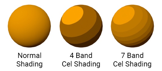
By setting threshold values for scalar products, you can create multiple bands. For example, if the scalar product is greater than -0.8, then the surface can be assigned a dark color, and if the scalar product is less than -0.8, then the color is light. So we will create a two-lane cel-shader.

The limitation of this method is that other light sources cannot influence objects with cel-shading. In addition, objects cannot cast shadows on objects with cel-shading.
GIF
To solve this problem, we must use a different method. Instead of calculating the scalar product, we will calculate the illumination of the surface. Then, when setting threshold values, it will be possible to use this value instead of the scalar product.
GIF
Now that you know what a cel shader is and how it works, it's time to create it.
Creating a Cel Shader
In this tutorial, cel shading will be a post-processing effect. Post-processing (Post processing) allows you to change the image after the engine finishes its rendering. Post-processing is commonly used for effects such as depth of field, motion blur, and bloom.
To create our own post-processing effect, we need to use the post-process material . Go to the Materials folder and create a new Material . Rename it to PP_CelShader and open.
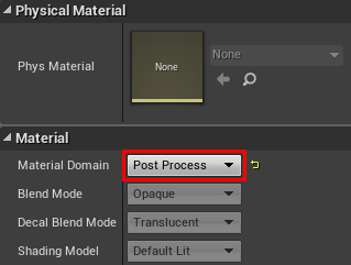
To convert material into post-processing material, you need to change its domain . Go to the Details panel and change the Material Domain to Post Process.
The first step in creating a cel shader is to calculate the illumination of each pixel. We will call this the lighting buffer .
Lighting Buffer Calculation
When Unreal renders an image on the screen, it saves the passes to the buffers. To calculate the lighting buffer, we will need to access two of these buffers:
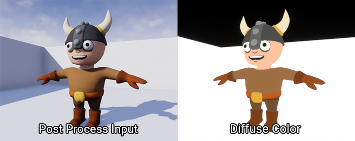
- Post Process Input: after Unreal has completed the lighting and post-processing, it saves the image to this buffer. It is his Unreal that will be displayed to the player if you do not perform further post-processing.
- Diffuse Color: This is a scene without any lighting or post-processing. It will contain the diffuse color of everything on the screen.
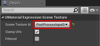
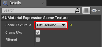
To access these buffers, you need to use the SceneTexture node . Create it, select and go to the Details panel. To access the Post Process Input buffer, change the Scene Texture Id to PostProcessInput0 .
To access Diffuse Color, create another SceneTexture node . Change its Scene Texture Id to DiffuseColor .
The lighting buffer should contain only grayscale values (describing the degree of illumination of pixels). This means that we do not need color information from both buffers. To discard colors, connect the Color output of both SceneTexture nodes to Desaturation . This will completely discolor both buffers.

To compute the lighting buffer, simply divide SceneTexture: PostProcessInput0 into SceneTexture: DiffuseColor . The order is important here!
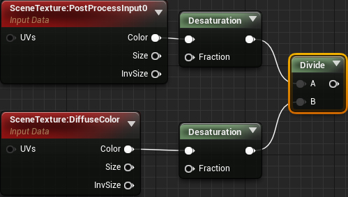
Then we use Clamp so that the values remain in the range from 0 to 1. This will simplify the creation of thresholds, because we will know the possible values.

Here is a visualization of the lighting buffer:
As you can see, illuminated areas are closer to white, and unlit areas are closer to black.
Then we use the lighting buffer to create the threshold.
Threshold creation
In our cel-shader, any pixel with a value greater than 0.5 will use the usual diffuse color. Pixels with values less than 0.5 will use a diffuse color of half brightness.
First, create an If node . It will allow us to compare two values. Depending on the results of the comparison, we will be able to indicate different outputs.

Further connect Clamp to the input A . Next, create a Constant with a value of 0.5 , and connect it to the input Bed and .
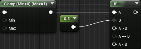
Note: to change the threshold, you can change the value of input B.
To get the colors, create a SceneTexture and set its Scene Texture Id to Diffuse Color . Then multiply Color by 0.5 to get a diffuse color of half brightness.

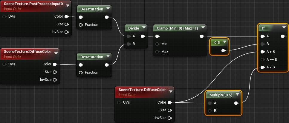
And finally, we connect everything as follows:

Summarize:
- Desaturation converts Post Process Input and Diffuse Color to grayscale images
- Divide divides Post Process Input into Diffuse Color . So we create a lighting buffer.
- Clamp limits values from 0 to 1
- If displays a normal diffuse color if the lighting value is greater than 0.5 . If it is less than 0.5 , then it displays a diffuse color of half brightness.
Now that we have the cel shader, we need to apply it to the scene.
Using post-processing materials
To use post-processing materials, we need to create a Post Process Volume . It is commonly used to control post-processing effects such as white balance, saturation, and contrast.
Click on Apply and return to the main editor. To create a Post Process Volume, go to the Modes panel and select the Volumes category . Then drag Post Process Volume to Viewport to create it.
GIF
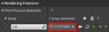
Now we need to tell Post Process Volume to use the cel shader. After selecting Post Process Volume, go to the Details panel. Then find the Rendering Features \ Post Process Materials and click on the + icon . So you add a new element to the array.

Then click on the Choose drop-down list and select Asset Reference .

This will allow you to choose the material. Click on the None drop-down list and select PP_CelShader .
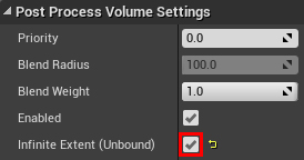
By default, Post Process Volume only works when we are inside. However, in our case, it is necessary that it affect the whole world. To do this, scroll to the Post Process Volume Settings and enable Infinite Extent (Unbound) .
Now that the cel shader is applied to the whole game, we will see the following:

“Wait a minute, this doesn't look like the cel shader you showed earlier!” The
main reason for this difference is that the engine uses the cel shader after tone compression. To fix this, we need to ask the engine to use the cel shader before tonal compression.
Application of Cel Shading before tone mapping
Before showing the image to the player, Unreal performs a process known as “tonemapping”. One of the goals of tonal compression is to make the image more natural. She takes an input color, and then uses a curve to shift it to a new value.
Here are two images before and after tone mapping:
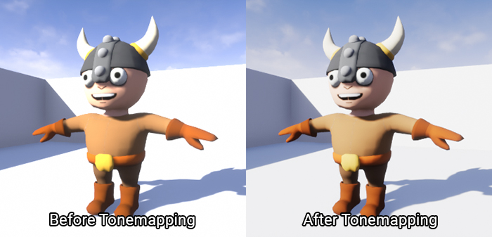
As you can see, the light areas before tonal compression are too bright. However, after tonal compression, the bright areas become softer.
Although tonal compression is useful for images that need to be displayed, we should not perform tonal compression for images that we want to use in calculations. Due to the bias of the values, we will not use the values that we expect.
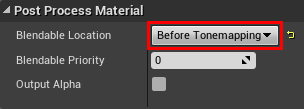
Open PP_CelShader and make sure nothing is selected. Then go to the panel and find the Post Process Material section . Set Blendable Location to Before Tonemapping .
Click on Apply , and then return to the main editor. Colors now look much better!
In the next section, we will learn how to apply cel shading only to individual objects.
Isolation Cel Shader
To isolate the effects of post-processing, we need to use a function called Custom Depth . Like Post Process Input with Diffuse Color, it is also a buffer that can be used in post-processing materials.
Before you understand what Custom Depth is, you need to understand the Scene Depth buffer . Scene Depth stores the remoteness of each pixel from the camera. Here's what the Scene Depth visualization looks like:

Custom Depth stores the same information, but only for the meshes you select. Here is his visualization with a viking rendered in Custom Depth:

Comparing Scene Depth with Custom Depth, we can isolate objects. If Scene Depth is smaller than Custom Depth, then we use a regular image. If Scene Depth is larger than Custom Depth, then an image with cel shading is used.
The first step is to render the viking in Custom Depth.
Using Custom Depth
Go to World Outliner and select SK_Viking . Then go to the Details panel and find the Rendering section . Then enable the Render CustomDepth Pass .

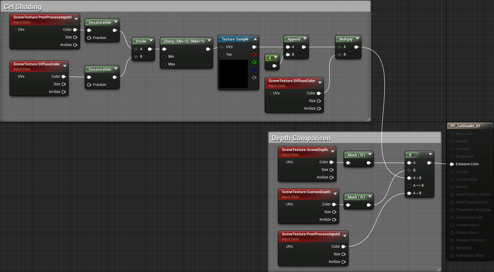
Next we need to do a depth comparison. Open PP_CelShader and create the following diagram:
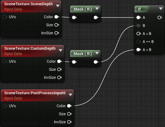
Note: The node Mask (R) are masks components ( Component Mask ). They allow you to convert multichannel data into scalar values. We need to mask the Scene Depth and Custom Depth because the If node for inputs A and B takes only scalar values.
Then, connect the output cel shading network A> B . Finally, connect the output of the newly created If to the Emissive Color .

Now cel shading will only apply to meshes rendered in Custom Depth.
Click on Apply , and then return to the main editor. You will see that cel shading is now performed only for the viking.

The cel shader works great, but it's pretty simple. What if we need more bands? What if we want to create smoother transitions between the bands? All this can be implemented using lookup tables (LUT).
What is a “lookup table"?
In childhood, we learned what multiplication is. However, the young brain could not always perform such calculations. Therefore, instead of calculations, you could use the multiplication table to “search” for answers.
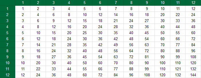
In fact, this is LUT. This is an array of values (usually pre-computed) that can be accessed using input data. In the case of the multiplication table, the input was the multiplier and the multiplier.
In the context of our cel-shader, LUT is a texture with a certain gradient. Here are four examples of what a LUT might look like:
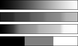
While we are calculating the color of the shadow, multiplying the diffuse color by 0.5. Instead of multiplying by a constant of 0.5, we will use the value from LUT. Thanks to this, we can control the number of lanes and their transitions. You can understand how the shading will look by the appearance of the LUT.
Before using LUT, you need to change some of its texture parameters.
Change LUT Settings
Go to the Textures folder and open T_Lut_01 . Here's what the LUT looks like:

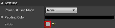
The first parameter we need to change is sRGB . When rendering, Unreal converts all textures with sRGB enabled to linear color. This simplifies the engine's rendering calculations.
The sRGB parameter is useful for textures that describe appearance. However, textures like normal maps and LUTs contain data intended for mathematical calculations. Therefore, Unreal must consider their values to be true. If you disable sRGB, then Unreal will not perform the conversion to linear color.
To do this, remove the check the sRGB . This parameter is located in the Texture section .
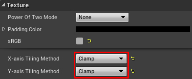
The next parameter we need to change is the texture tiling method . Since we will not display this texture, it does not need tiling. Moreover, if you leave tiling enabled, it will add problems when sampling at the edges of the texture. For example, if we sample a pixel from the left edge, then due to tiling it will try to mix with the right edge.
To disable tiling, change the value of the X-axis Tiling Method to Clamp . Do the same for the Y-axis Tiling Method .
And we are done with the parameters. Now we need to use LUT in the post-processing material.
Using LUT
Close T_Lut_01 and open PP_CelShader . First delete the selected nodes:
Then create a Texture Sample and change its Texture to T_Lut_01 . This LUT table will create three bands with a smooth transition.

As we recall, the LUT uses the input to determine the values to be output. In our case, the lighting buffer will be used as input.
To implement this, combine Clamp with UVs in the Texture Sample .
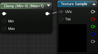
This works because the values of the lighting buffer and texture coordinates are between 0 and 1. For example, if the pixel from the lighting buffer is 0.5, then LUT will output the pixel value from the middle of the texture.
Next we need to multiply the diffuse color by LUT. To do this, recreate the following diagram:
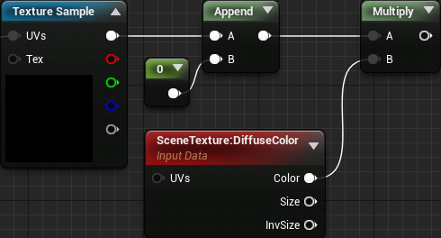
We use Append to convert Texture Sample’s output to a four- channel vector. We need this because we cannot multiply a three-channel vector by a four-channel ( SceneTexture ).
Finally, connect everything as follows:
Now, instead of multiplying the diffuse color by a constant, we multiply it by the value from LUT. So we control the number of color bands and their transitions (depending on the LUT). The output LUT value is determined by the lighting buffer.
Click on Apply and then close PP_CelShader . Now the shader will have three bands with smoother transitions between the bands.
The following is a comparison of how the various LUTs might look. These LUTs are also added to the project.

Where to go next?
The finished project can be downloaded from here .
As you can see, post-processing materials are a very powerful tool. They allow you to create many realistic and stylized effects. If you want to learn more about post-processing, check out the documentation for post-processing UEs .