Fast shader for Unity Subsurface Scattering
- Transfer

Most (if not all) of the optical phenomena demonstrated by materials can be recreated by simulating the propagation and interaction of individual rays of light. This approach is called “ray tracing” in the scientific literature and is often too computationally expensive to use in real time. Most modern engines use strong simplifications, which, despite the impossibility of creating photorealism, can provide fairly convincing approximate results. In this tutorial, I’ll talk about a quick, cheap, and convincing solution that you can use to simulate translucent materials with subsurface scattering .
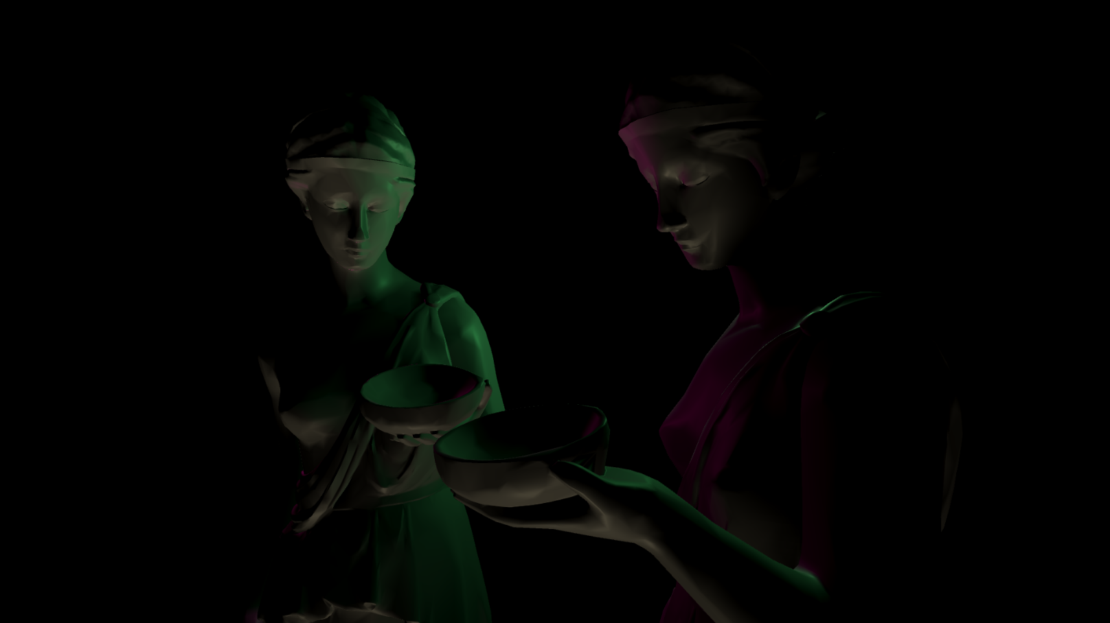
Before ...
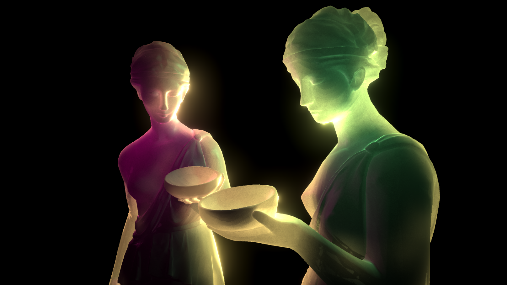
... and after.
Introduction
The standard Unity material has a Transparency mode, which allows rendering transparent materials. In this context, transparency is implemented using alpha blending . A transparent object is rendered over the finished geometry, partially showing what is behind it. This works for many materials, but accrual is a special case of a more general property called translucency (sometimes also translucidity ). Transparent materials affect only the amount of light transmitted through them (in the figure below on the left), translucent ones change the path of its passage (on the right).
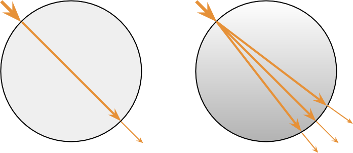
The result of this behavior is obvious: translucent materials scatter the rays of light passing through them, eroding what is behind the object. This behavior is rarely used in games, because it is much more difficult to implement. Transparent materials can be implemented in a straightforward manner - alpha blending, without ray tracing. Translucent materials, however, require a simulation of the deviation of light rays. Such calculations are very costly and rarely worth the trouble when rendering in real time.
This often interferes with the simulation of other optical phenomena, such as subsurface scattering. When light falls on the surface of the translucent material, part of it propagates inward, colliding with molecules, until it finds a way out. Often this leads to the fact that light absorbed at one point is emitted by the material at another point. Subsurface scattering leads to the creation of a diffuse glow, which can often be seen on materials such as human skin, marble, and milk.
Real Time Translucency
Transmission calculations cost two major hurdles. First, a simulation of the scattering of light rays inside the material is required. Each beam can be divided into several, reflected hundreds or even thousands of times inside the material. The second obstacle - a ray absorbed at one point, is emitted at some other. This seems like a small problem, but in fact it is a serious obstacle.
To understand why this happens, we first need to figure out how most shaders work. In the real-time rendering industry, the video processor expects the shader to be able to calculate the final color of the material using only local properties. Shaders are implemented in such a way that they can effectively access only properties that are local to each vertex. You can very easily calculate the direction of the normal and albedo peaks, but getting these values from neighboring peaks is not an easy task. In most real-time systems, you have to somehow circumvent these limitations and find a way to simulate the propagation of light in a material without using non-local information.
The approach described in this tutorial is based on the solution presented at GDC 2011 by Colin Barre-Brisebois and Marc Bouchard in the report Approximating Translucency for a Fast, Cheap and Convincing Subsurface Scattering Look . Their solution is integrated into the Frostbite 2 engine , which was used in the DICE Battlefield 3 game . Although the approach presented by Colin and Mark is physically inaccurate, it provides plausible results at a very low cost.
The idea behind this solution is very simple. Opaque materials are directly affected by light from a light source. Vertices tilted more than 90 degrees from the direction of light
 , do not receive lighting at all (in the figure below left). In accordance with the model presented in the report, there is an additional effect of light on transmitted materials, which is associated with
 . Geometrically can be perceived as if part of the lighting actually goes through the material and gets to its back side (in the figure below to the right).
That is, each light source is considered as two separate effects on reflection: the lighting of the front and rear. We want our materials to be as realistic as possible, so we use standard Unity PBR lighting models for front lighting. We need to find a way to describe the impact.
and render it in such a way that it somehow simulates the dispersion process that could take place inside the material.Back translucency
As stated above, the final color of the pixels depends on the sum of the two components. The first one is “traditional” lighting. The second is the effect of light from a virtual source illuminating the back of the model. This will give us the feeling that the light from the original source actually passed through the material.
To understand how to model this mathematically, let's create a diagram of the following two cases (diagrams below). We are currently drawing a red dot. Since it is on the “dark” side of the material, it should illuminate
. Let's analyze two extreme cases from the point of view of an outside observer. We see that is in line with and parallel to it, and that means the observer
  should fully see back translucency. The observer, on the other hand
 should see the least amount of backlighting because it is perpendicular to .
If you are familiar with writing shaders, then such reasoning should be familiar to you. We have already encountered something similar in the tutorial Physically Based Rendering and Lighting Models in Unity 5 , where we showed that such behavior can be implemented using a mathematical operator called a scalar product .
As a first approximation, we can say that the amount of backlighting due to translucency,
 proportionally
  . In a traditional diffuse shader, this is written as
 . We see that we did not include the normal to the surface in the calculations , because the light simply comes from the material, and is not reflected from it.
Subsurface distortion
However, the normal to the surface should have some effect, at least a small one, on the angle at which light emanates from the material. The authors of this technique introduced a parameter called subsurface distortion.
 Forcing Vector point towards
  . From the point of view of physics, this subsurface distortion controls the degree of deviation from the normal to the surface of the outgoing backlight. In accordance with the proposed system, the intensity of the component of reverse transillumination turns into:
Where
 Is a unit vector pointing in the same direction as
  . If you are familiar with Cg / HLSL, then this is a feature
 normalize. At
 we come back to obtained in the previous section. However, when
 we calculate the scalar product between the direction of view and
  . If you know the Blinn-Fong reflection calculation , then you should know that
 Is the vector between and . Therefore we will call it half direction
 .
.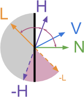
The diagram above shows all the directions that we have so far used.
marked in purple and you see that it is between and . In terms of geometry, change from  before
  leads to a shift in the perceived direction of light . The shaded area shows the range of directions from which the backlight will come. The figure below shows that forthe subject appears lit from a purple light source. When it changes to 1 the perceived direction of the light source shifts to purple.
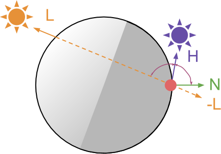
Destination
- simulation of the tendency of some translucent materials to diffuse backlighting with different intensities. Higher values, the more backlight is scattered.Does the value of H here have the same meaning as H in calculating the reflection according to Blinn-Fong?
Not. Reflected by Blinnu-Fong defined as  . Here we use the same letter to denote.
defined as . Here we use the same letter to denote.Is the delta interpolated between L and L + N?
Yes. Values from before linearly interpolated between and  . This can be seen by expanding the traditional definition of linear interpolation from and from :


from before linearly interpolated between and . This can be seen by expanding the traditional definition of linear interpolation from and from :Why did it happen that the authors did not normalize L + N?
From a geometric point of view, the quantity does not have a unit length, that is, it must be normalized. In their final system, the authors do not perform normalization.
In the end, this whole effect should not be either photorealistic or physics-based. In their report, the authors made it very clear that it is intended to be used as a quick approximation of translucency and subsurface scattering. Normalization does not greatly change the results, but adds significant delays.
does not have a unit length, that is, it must be normalized. In their final system, the authors do not perform normalization. In the end, this whole effect should not be either photorealistic or physics-based. In their report, the authors made it very clear that it is intended to be used as a quick approximation of translucency and subsurface scattering. Normalization does not greatly change the results, but adds significant delays.
Backlight diffusion
At this stage of the tutorial, we already have an equation that can be used to simulate translucent materials. Magnitude
cannot be used to calculate the final effect of lighting. Two main approaches can be used here. The first is to apply a texture. If you need complete artistic control over how light is scattered in the material, then you need to limit
in the range from before and use it to sample the final backlight intensity. Textures with different linear variation will simulate the propagation of light in different materials. Below we will look at how this can be used to significantly change the results of this shader. However, the approach used by the author of this technique does not apply texture. In it, the curve is created only by the Cg code:

Two new options,
 ( degree ) and
 ( scale ) are used to change the properties of the curve.
Conclusion
In this part of the article, we talked about the technical difficulties of rendering translucent materials. An approximating solution and approach are presented in the report Approximating Translucency for a Fast, Cheap and Convincing Subsurface Scattering Look . In the next part of the tutorial, we will focus on the very implementation of this effect in the Unity shader.
If you are interested in more sophisticated approaches to simulating subspace dispersion in real-time applications, then you can study one of the best GPU Gems tutorials .
Part two
Introduction
The previous part of the tutorial explained the mechanism that allows you to approximate the appearance of translucent materials. The shading of traditional surfaces is based on the illumination received from
. The shader we write will add another componentwhich will be used de facto as if the material is illuminated by a light source from the back. In this case, it will look as if the light from passes through the material.Finally, we derive a direction-dependent equation for modeling reflection from backlight:
Where:
- - this is the direction from which light comes ( direction of light ),
 - the direction of the camera looking at the material (the direction of view ),
- - orientation of the surface at the point to be rendered ( normal to the surface ).
There are additional parameters that can be used to control the final appearance of the material. for instance
changes the perceived direction of backlighting so that it is more parallel to the normal to the surface:And finally
and ( degree and scale ) determine the distribution of backlighting and work in a manner similar to the parameters of the same name in calculating reflection according to Blinn-Fong . Now we just have to implement the shader.
Expanding the capabilities of the standard shader
As described above, we want this effect to be as realistic as possible. The best solution would be to expand the functions of the standard shader (Standard shader) Unity, which initially provides fairly good results for opaque materials.
How to expand the capabilities of a standard shader?
Если вам незнакома эта процедура, тема расширения функциональности стандартного шейдера подробно рассмотрена в моём блоге. Два неплохих туториала для начала: 3D Printer Shader Effect (перевод на Хабре) и CD-ROM Shader: Diffraction Grating.
Если коротко, то основная идея заключается в создании нового поверхностного шейдера и замене его функции освещения на собственную. Здесь мы будем вызывать исходную стандартную функцию освещения, чтобы материал рендерился с помощью PBR-шейдера Unity.
Создав его, мы сможем вычислять влияние обратного освещения и смешивать его с исходным цветом, предоставляемым стандартной функцией освещения. Для хорошей аппроксимации:
Можно начать со следующего:
#pragma surface surf StandardTranslucent fullforwardshadows
#pragma target 3.0
sampler2D _MainTex;
struct Input {
	float2 uv_MainTex;
};
half _Glossiness;
half _Metallic;
fixed4 _Color;
#include "UnityPBSLighting.cginc"
inline fixed4 LightingStandardTranslucent(SurfaceOutputStandard s, fixed3 viewDir, UnityGI gi)
{
	// Исходный цвет
	fixed4 pbr = LightingStandard(s, viewDir, gi);
	// ...
	// Изменяем здесь "pbr", чтобы добавить новый источник
	// ...
	return pbr;
}
void LightingStandardTranslucent_GI(SurfaceOutputStandard s, UnityGIInput data, inout UnityGI gi)
{
	LightingStandard_GI(s, data, gi);
}
void surf (Input IN, inout SurfaceOutputStandard o) {
	// Albedo получается из текстуры, подкрашенной цветом
	fixed4 c = tex2D (_MainTex, IN.uv_MainTex) * _Color;
	o.Albedo = c.rgb;
	// Metallic и smoothness берутся из переменных ползунков
	o.Metallic = _Metallic;
	o.Smoothness = _Glossiness;
	o.Alpha = c.a;
}
Let's call a new light function, which we will use in this effect
StandardTranslucent. Backlight will have the same color as the original lighting. We can only control the intensityI#pragma surface surf StandardTranslucent fullforwardshadows
#include "UnityPBSLighting.cginc"
inline fixed4 LightingStandardTranslucent(SurfaceOutputStandard s, fixed3 viewDir, UnityGI gi)
{
// Исходный цвет
fixed4 pbr = LightingStandard(s, viewDir, gi);
// Вычисляем интенсивность обратного освещения (просвечивание света)
float I = ...
pbr.rgb = pbr.rgb + gi.light.color * I;
return pbr;
}Why is the range of pbr values unlimited?
When adding two colors, you need to be careful that the value does not exceed . This is usually implemented by a function before .
If your camera uses HDR ( high-dynamic range, extended dynamic range ) support , then the values are higherapply to post-processing effects such as bloom. In this shader, we do not saturate the final color, because the bloom filter will be applied during the final rendering.
. This is usually implemented by a function saturatethat limits each of the color components to an interval from before . If your camera uses HDR ( high-dynamic range, extended dynamic range ) support , then the values are higher
apply to post-processing effects such as bloom. In this shader, we do not saturate the final color, because the bloom filter will be applied during the final rendering.Backlight
In accordance with the equations described in the first part of the tutorial, we can write the following code:
inline fixed4 LightingStandardTranslucent(SurfaceOutputStandard s, fixed3 viewDir, UnityGI gi)
{
	// Исходный цвет
	fixed4 pbr = LightingStandard(s, viewDir, gi);
	// --- Просвечиваемость ---
	float3 L = gi.light.dir;
	float3 V = viewDir;
	float3 N = s.Normal;
	float3 H = normalize(L + N * _Distortion);
	float I = pow(saturate(dot(V, -H)), _Power) * _Scale;
	// Конечное сложение
	pbr.rgb = pbr.rgb + gi.light.color * I;
	return pbr;
}
The above code is a direct implementation of the equations from the first part of the article. The resulting translucency effect looks quite plausible, but it has nothing to do with the thickness of the material. Therefore, it is very difficult to manage.

Local thickness
Obviously, the amount of backlighting is highly dependent on the density and thickness of the material. Ideally, we need to know the distance traveled by the light inside the material, and weaken it accordingly. As can be seen from the figure below, three different beams with the same angle of incidence travel very different distances within the material.

From the point of view of the shader, we do not have access to either local geometry or the history of light rays. Unfortunately, there is no way to solve this problem locally. It will be best to use an external map of local thicknesses . This is a texture associated with the surface that defines the “thickness” of the corresponding part of the material. The concept of “thickness” is used arbitrarily, because the real thickness depends on the angle at which light falls.

The diagram above shows that there is no unique concept of “thickness” associated with the red dot of a circle. The amount of material through which the light passes actually depends on the angle of incidence of the light
. That is, we need to remember that this whole approach to the realization of translucency does not strive for physical accuracy, but to deceive the player’s eye. Below ( source ) a good map of local thicknesses is shown, visualized on the model of the statue. The shades of white correspond to parts in which the translucent effect will be stronger, approximating the concept of thickness.
How to generate a map of local thicknesses?
The author of this technique proposed an interesting way to automatically create a map of local thicknesses from any model. To do this, follow these steps:
The logic of this process is that when rendering ambient occlusion on the back faces, you can approximately " average the entire light transport inside the object ."
Instead of texture, thickness can be stored directly at the vertices.
- Invert model faces
- Render into Ambient Occlusion texture
- Invert texture colors
The logic of this process is that when rendering ambient occlusion on the back faces, you can approximately " average the entire light transport inside the object ."
Instead of texture, thickness can be stored directly at the vertices.
Final version
Now we know that we need to take into account the local thickness of the material. The easiest way to do this is to create a texture map that you can sample. Although this is physically inaccurate, we will get convincing results. In addition, the local thickness is encoded in such a way that allows artists to fully control the effect.
In this implementation, the local thickness is stored in the red channel of the additional texture sampled in the surf function :
float thickness;
void surf (Input IN, inout SurfaceOutputStandard o)
{
	// Albedo получается из текстуры, подкрашенной цветом
	fixed4 c = tex2D (_MainTex, IN.uv_MainTex) * _Color;
	o.Albedo = c.rgb;
	// Metallic и smoothness берутся из переменных ползунков
	o.Metallic = _Metallic;
	o.Smoothness = _Glossiness;
	o.Alpha = c.a;
	thickness = tex2D (_LocalThickness, IN.uv_MainTex).r;
}
How is it that the texture is not sampled in the lighting function?
Я решил хранить это значение в переменной
Если вы предпочитаете делать иначе, то можете сэмплировать текстуру непосредственно в функции освещения. В этом случае необходимо передавать UV-координаты (возможно, расширив
thickness, к которой позже получает доступ функция освещения. Лично я стремлюсь делать так всегда, когда мне приходится сэмплировать текстуру, которая позже потребуется функции освещения.Если вы предпочитаете делать иначе, то можете сэмплировать текстуру непосредственно в функции освещения. В этом случае необходимо передавать UV-координаты (возможно, расширив
SurfaceOutputStandard) и использовать tex2Dlod вместо tex2D. Функция получает две дополнительные координаты. В нашем случае можно задать им значение «ноль»:thickness = tex2Dlod (_LocalThickness, fixed4(uv, 0, 0)).r;Colin and Mark proposed a slightly different equation for calculating the final backlight intensity. It takes into account both the thickness and the additional attenuation parameter . In addition, they allowed the possibility of using the constantly present additional component of the environment :
inline fixed4 LightingStandardTranslucent(SurfaceOutputStandard s, fixed3 viewDir, UnityGI gi)
{
	// Исходный цвет
	fixed4 pbr = LightingStandard(s, viewDir, gi);
	// --- Просвечиваемость ---
	float3 L = gi.light.dir;
	float3 V = viewDir;
	float3 N = s.Normal;
	float3 H = normalize(L + N * _Distortion);
	float VdotH = pow(saturate(dot(V, -H)), _Power) * _Scale;
	float3 I = _Attenuation * (VdotH + _Ambient) * thickness;
	// Конечное сложение
	pbr.rgb = pbr.rgb + gi.light.color * I;
	return pbr;
}
Here is the final result:
Conclusion
The approach described in the article is based on the solution presented at GDC 2011 by Colin Barre-Brisebois and Marc Bouchard in the report Approximating Translucency for a Fast, Cheap and Convincing Subsurface Scattering Look .
All the files necessary for starting the project (shader, textures, models, scenes) can be downloaded from my page on Patreon [approx. transl .: for 10 dollars] .