September 1, 2017 at 16:13
Joystick on AT91SAM7
Introduction
It so happened that my baby, as befits a boy, is fond of cars. When he grew up to 5 years old, he started playing the Master Rally simulator. Playing alone is not interesting, so I began to take part in this. It soon became clear that discrete keyboard control does not allow me to compete and fight for victory equally. Then I thought of a second steering wheel.
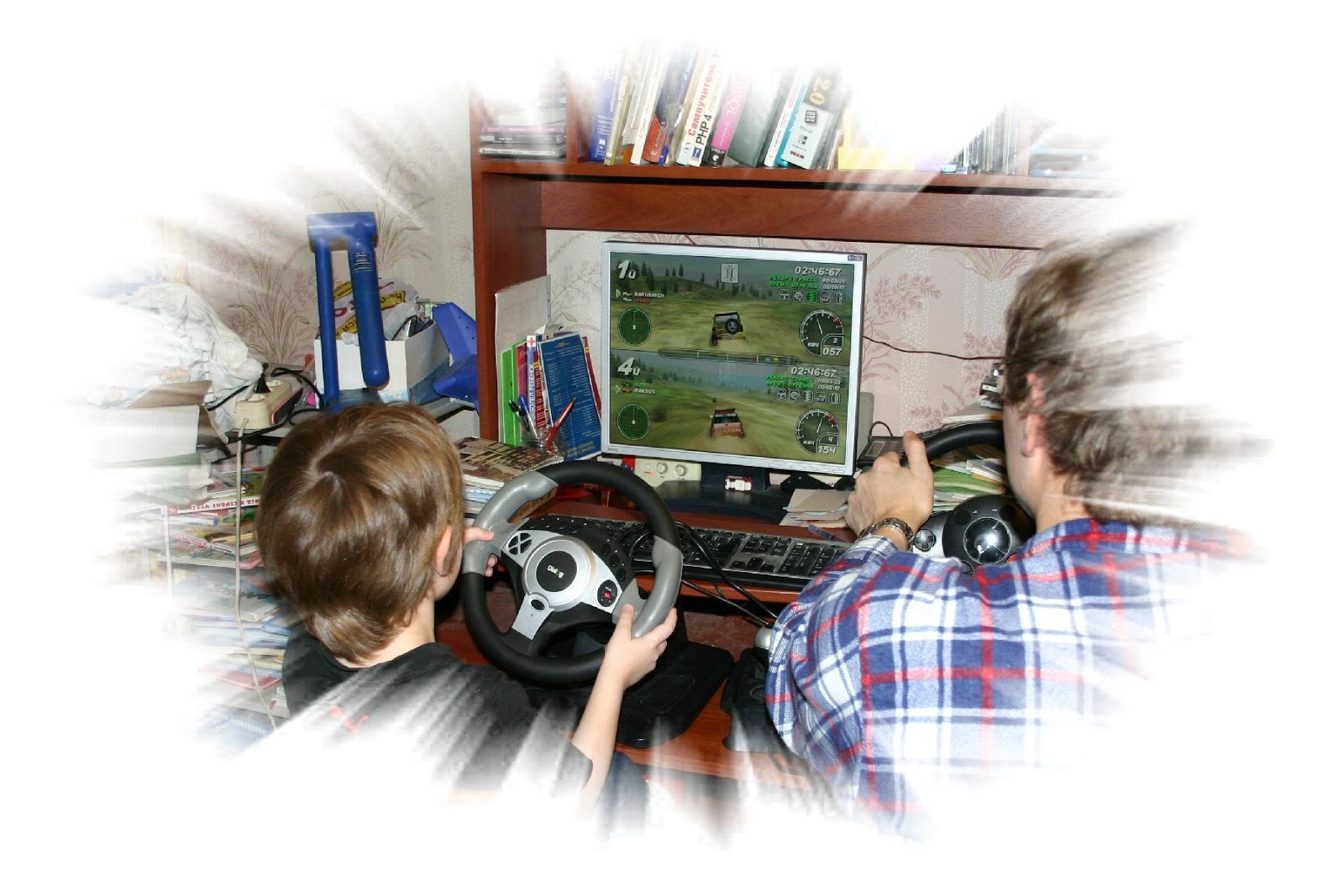
It turned out that each time to get and install 2 steering wheels is a difficult and very annoying procedure. Therefore, I decided to buy a pistol-style joystick - both for controlling radio-controlled cars.
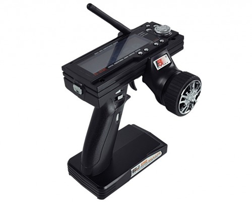
Searching the Internet, I realized that these are not produced and not sold. Since I was already familiar with the AT91SAM7 controller, I decided to quickly make a USB joystick based on it using the simplest joystick from an old radio-controlled toy. This article describes how to do this. I have been using it for a year, but I decided to share it.

What to use?
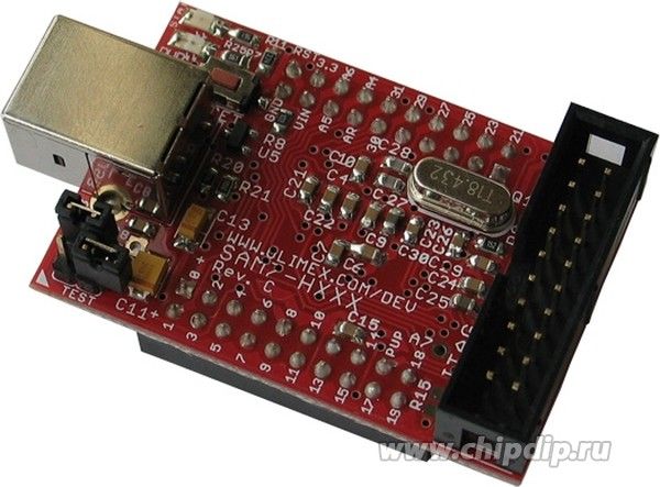
The joystick is made on the basis of the Olimex debug board . You can read more about this board in this document .
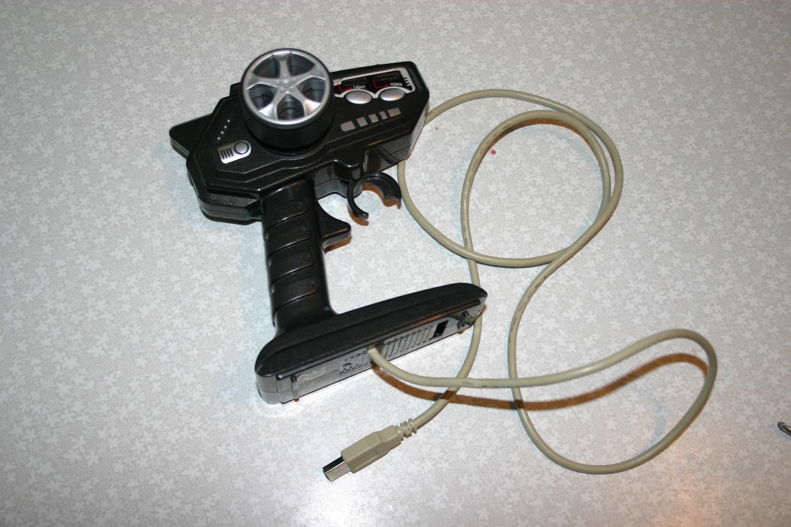
We also need a joystick from some old radio-controlled toy and a USB cable. Here is the result. Inside the standard joystick with 3 buttons and two LEDs, a debug board was added. The most complex design element was the connection of the trigger with the variable resistor R1. (See diagram ) Here I used a resistor with a non-linear characteristic to get a larger change in resistance with a small angle of rotation.
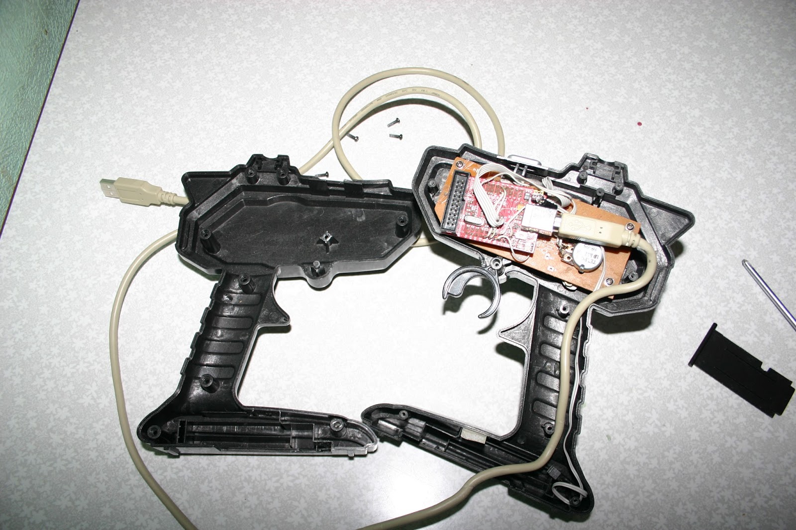
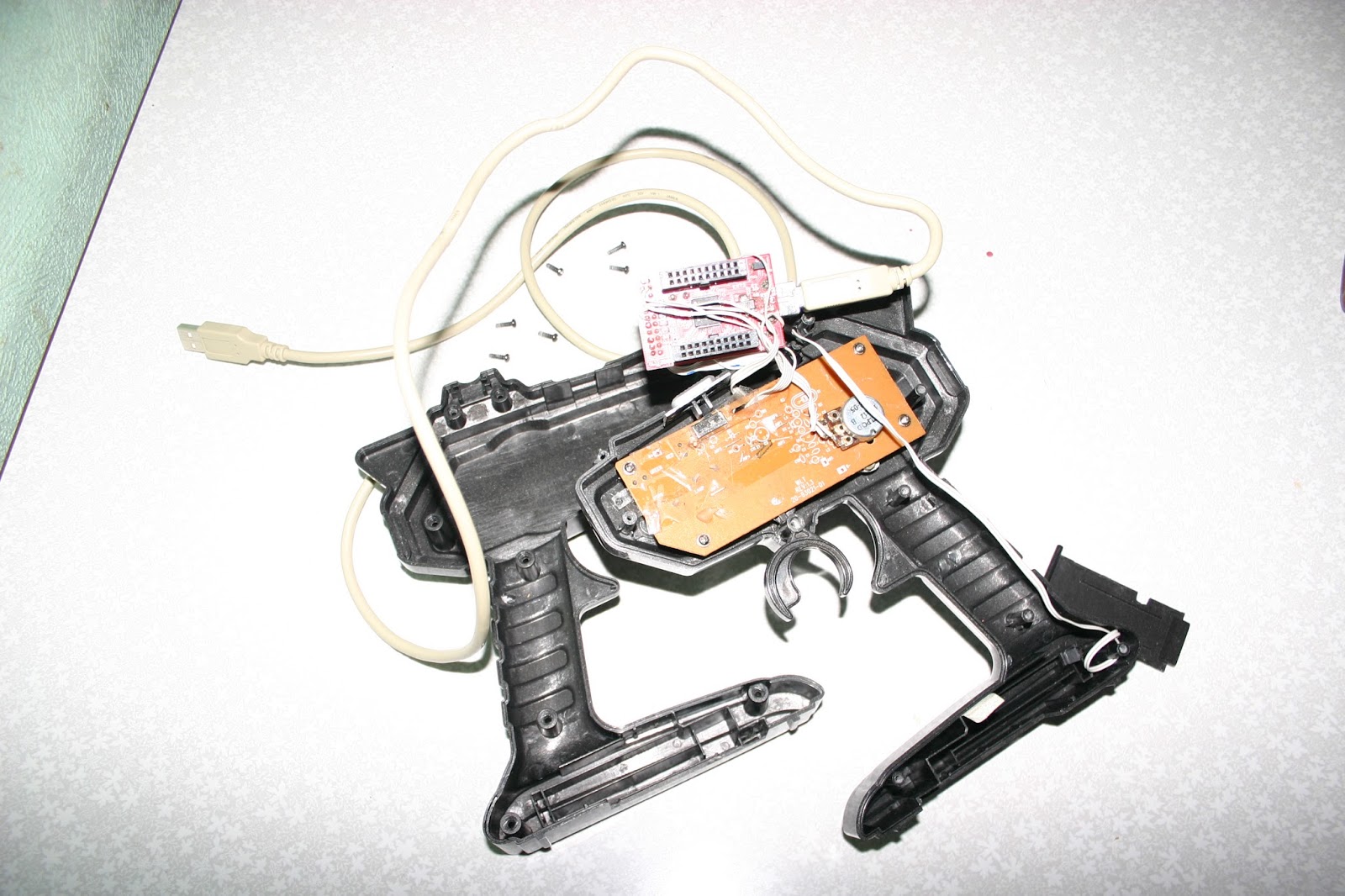
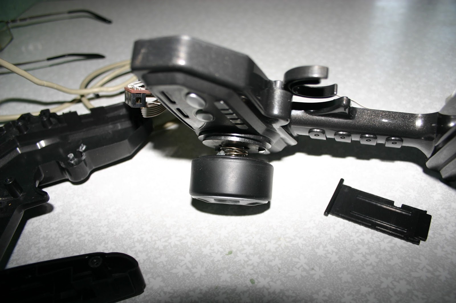
Initially, there was no return spring on the steering wheel (Resistor R2). But practice has shown that it’s difficult to control at the same time, since the fingers do not feel the current position of the steering wheel, which leads to a violation of the tactile feedback between the steering wheel and the person. The photo below shows how the spring is installed.
Scheme
Here is the circuit :
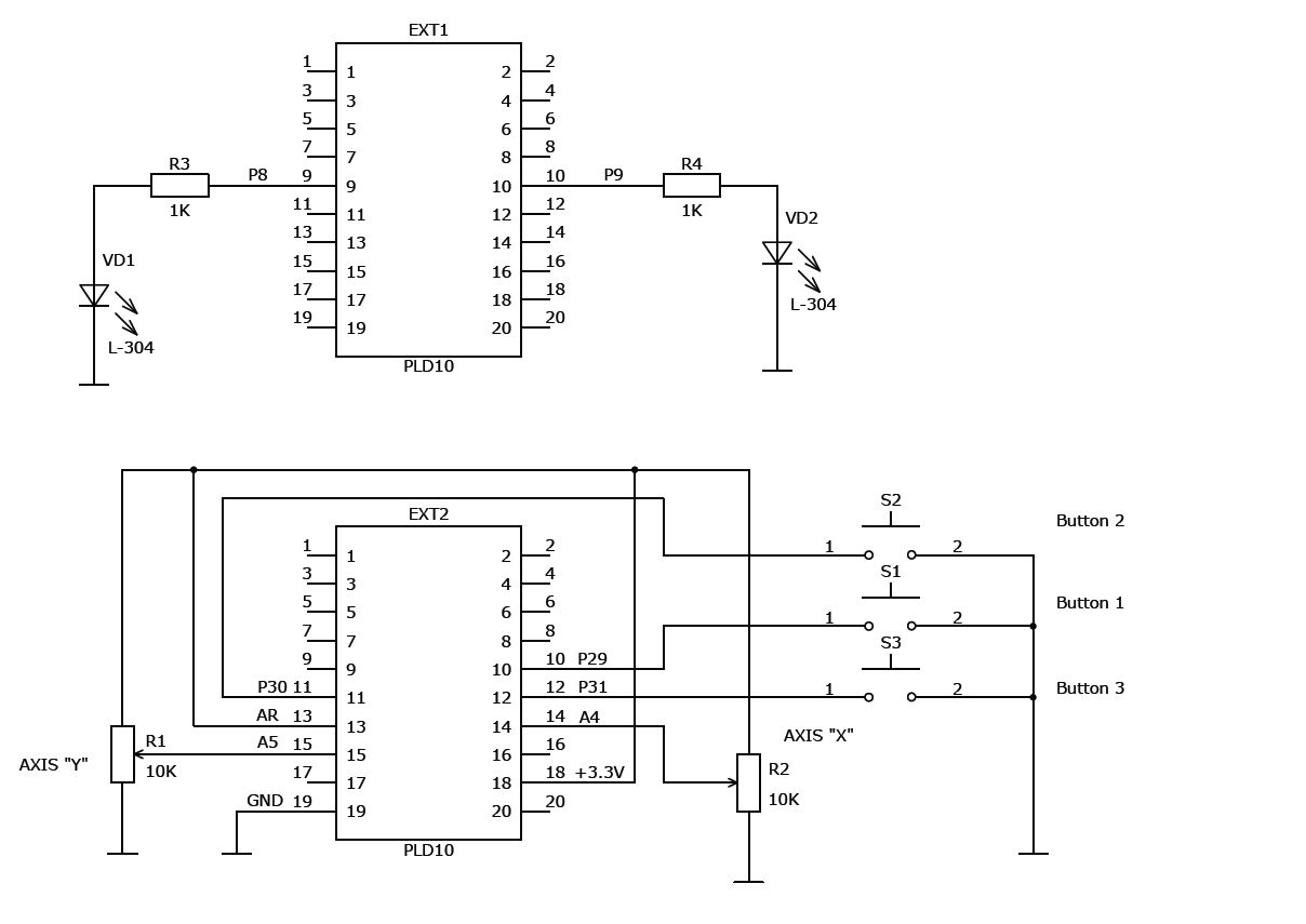
It is necessary to add that variable resistors can be from 1 to 15 kOhm, and preferably with a linear characteristic for the steering wheel, for gas and brake - optional. First, I put the old wire (as I thought more reliable) resistor on the steering wheel, but after a couple of months it died, so it was replaced by a regular imported one, which turned out to be more reliable. The VD1 LED is flashing; it blinks in short flashes if the device has successfully connected to the computer. VD2 lights up when the S3 button is turned on.
Software
To write the program, examples were used from the Atmel disc, which are freely available on the Internet. Here you can find the project. In this project lies the working binary for the AT91SAM7S256 version. (\ Mouse \ FLASH \ Exe \ USB.bin) You can directly upload it to the controller. For version S64, the binary itself was not checked when writing a blog. Those who want to tinker or change something can set up an IAR Systems environment and indulge. The advantage of the project is that it does not require a special driver for Windows XP or 7, it is picked up by the system as a standard joystick. If desired, you can change the number of buttons and axes. The controller contains an 8-channel ADC and many ports. To program the controller via the USB port, you need to use the SAM-BA 2.15 program. All information and this program are available on the Atmel website.