WIFI in the subway: network architecture and underground stones
In just a couple of years, a Muscovite trip in the subway has ceased to be a daily routine. If earlier the only entertainment in the subway was reading books, the press and an MP3 player, now online shopping, watching TV shows, business correspondence, even dating in Tinder and quests have been added to them. And all thanks to the appearance of a free Wi-Fi network in the metro. About 80% of Muscovites regularly connect to the MT_FREE network in the metro, without thinking about how it works and by whose forces it is done. There is an opinion that Wi-Fi in the metro “spent” the metro itself, but this is not entirely true. Wireless network is a project of MaximaTelecom. For the company, this was the first experience in building a high-speed Wi-Fi network with engineering and technical solutions unique in world practice. In this post we will tell you how the Wi-Fi network is organized in the Moscow metro.
In fact, we have two networks ...
The radio network inside the carriages
You enter the carriage, see a sticker with the name of the network, or, as usual, turn on Wi-Fi on your phone. At the same time, the device connects to the network with the SSID MT_FREE. It is organized by high-density access points that are located in each car, operate in two 2.4 GHz and 5 GHz bands and support 802.11a / b / g / n standards. The controller in the head carriage controls them. There are two of these cars, which means there are also two controllers. All equipment in rolling stock, including between cars, is connected by cables - twisted pair.
Matter of technology
We used Cisco equipment to organize the Wi-Fi network and network infrastructure in the rolling stock: in particular, air-cap2602i access points, air-ct2504 controllers, 29xx series switches and 8xx series routers. To increase the fault tolerance between the cars, we laid two cable routes. If we delve into the network architecture, then Layer2 for user traffic is terminated on a rolling stock router, and NAT (network address translation) is performed on network edge routers in the same way as it is organized with most wire access operators.
Tunnel Radio Network
After passing through the internal train network, the data is transmitted to the stationary network infrastructure using the train-tunnel radio channel. It is installed between the base station located in each head carriage and the base stations located along the rolling stock in the tunnel, as well as in open sections of the tracks. The location of the base stations along the tracks is such that the train moves in a continuous radio field. Thanks to this, communication breaks are minimal. Base stations on the train are located in the same way as access point controllers on each head carriage, while only one of the stations is active during train movement. The radio channel operates in the same frequency range as Wi-Fi - 5 GHz, but uses a proprietary data transfer protocol. Unlike the equipment inside the train,
Matter of technology
The equipment manufactured by Radwin 5000 series is used to organize the communication channel. It uses Wi-Fi chips that comply with the 802.11n standard, while the data is transmitted using a proprietary protocol based on TDM (Time Division Multiplexing), which is formed by an additional chip. Base stations are synchronized using a protocol similar to PTP 1588v2.
The allowed frequency spectrum 5150 - 5350 MHz is divided into five disjoint channels of 40 MHz each. All five channels are used on each line, usually in the sequence 1-3-5-2-4, in order to maximally avoid the influence of interference when neighboring devices operate in the same frequency range.
The allowed frequency spectrum 5150 - 5350 MHz is divided into five disjoint channels of 40 MHz each. All five channels are used on each line, usually in the sequence 1-3-5-2-4, in order to maximally avoid the influence of interference when neighboring devices operate in the same frequency range.
Network architecture

Each base station on the route of the train is connected to the switching nodes located in the office premises of the subway using a dedicated fiber-optic network. Uninterrupted power supply of base stations is also organized with the help of equipment installed in these switching nodes.
The architecture of the fixed data network is no different from the typical architecture of telecom operators. This is a “double star” with geographical redundancy of communication channels and key equipment. The network has several communication channels with backbone telecom operators, with a total bandwidth of more than 60 Gb / s.
Matter of technology
Network equipment at the access level (switches into which base stations are directly connected), aggregations, and also kernels are presented by Cisco switches and routers.
Base stations are connected to switches using WDM technology to save fibers (that is, one fiber at different wavelengths simultaneously receives and transmits data). Access switches have two uplink with geo-reservation (FOCL cables are physically located in different tunnels) to aggregation switches of 1 Gbit / s each. Those, in turn, are connected via geo-reserved communication lines to the core switches, but already with 10 Gbit / s interfaces.
Base stations are connected to switches using WDM technology to save fibers (that is, one fiber at different wavelengths simultaneously receives and transmits data). Access switches have two uplink with geo-reservation (FOCL cables are physically located in different tunnels) to aggregation switches of 1 Gbit / s each. Those, in turn, are connected via geo-reserved communication lines to the core switches, but already with 10 Gbit / s interfaces.
Houston, we have problems ...
Technological difficulties
To work in the subway you need equipment:
- withstanding harsh operating conditions in the tunnel (suspended metal dust and engine oil) and on rolling stock (sudden changes in temperature and vibration);
- meeting the requirements of the subway (use non-combustible materials, comply with the requirements for electromagnetic compatibility, work from non-standard power sources);
- having the functionality necessary for the operation of the network.
In the subway in rolling stock, direct current with a rated voltage of 80V is used. However, depending on the condition of the batteries and the number of gaps in the contact rail, the real voltage “jumps” from 30V to 150V .
We were unable to find an affordable power supply unit with such parameters, and the cost of suitable options made the project inappropriate.
Here, the Sibcontact company from Novosibirsk helped us a lot. To our requirements, our colleagues made a power supply, which we successfully tested and subsequently used in all trains. The devices turned out to be very reliable, inexpensive, and the supplier managed to produce the required quantity in a few weeks, not months, as is usually the case.
Also we encounteredwith non-standard power supply in the tunnel - a two-phase network with a voltage of 127V. It is impossible to power equipment operating from a single-phase 220V network from it, and we pulled out new cables from our own power sources installed in the technical rooms of the stations. This increased the reliability of the network, because we used uninterruptible power supplies and automatic transfer switches.
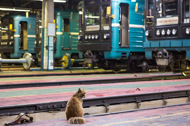
The variety of train types caused great difficulties.. This influenced the work on designing the placement of equipment for local networks of trains - it was colossal. Secondly, during the construction it turned out that almost all formulations, even of the same series and year of manufacture, are different. This is due to the fact that they were constantly upgraded and installed additional equipment. Such work was carried out separately for each train, and each time we equipped the train in a unique way.
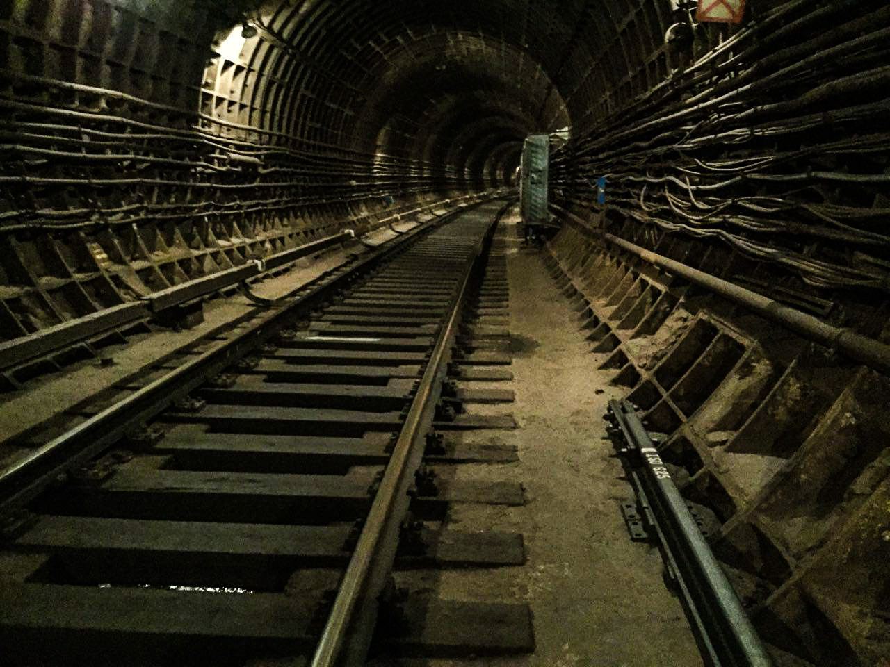
Serious questions arose during the radio planning of the network. They were associated both with the variety of materials from which the tunnels are made , and with a lack of initial information on their design, geometry, as well as branches and obstacles.
We ourselves completely examined all the tunnels - there are more than 330 km in the Moscow metro, and more than 660 km in double-track calculation. We applied certain metrics and rules for the placement of base stations, and after installation and commissioning of the equipment during operation, we measured the radio coverage and clarified the optimal locations for the equipment. We had to transfer some base stations after installation.
These difficulties compelled us, together with colleagues from the Nizhny Novgorod company Radio Gigabit, to conduct research work and develop a unique method of radio planning in tunnels, which is based on the simulation (mathematical modeling) of the channel and system level of the transport radio network in tunnels and in open areas. In new projects, we no longer guess, but know exactly how to arrange the equipment to obtain the specified characteristics of the channel.
Architectural difficulties
The main equipment that forms the radio channel between the train and the tunnel is located in the “head” (we remember that there are two of them), while cars upon arrival at the depot in rolling stocks are constantly changing. The network operates in constant motion, as a result of which the network ports and physical devices change all the time through which the traffic of the same sessions from the same composition goes. In this regard, we solved a number of architectural problems:
- fully automatic configuration of the train network when replacing or changing the order of cars
- distribution of intra-car access points between two W-Fi controllers in a train
- correct receipt by users and equipment of IP addresses
- “Exit” of user traffic through the correct base station that is currently active
- jumping MAC addresses from one port of a stationary switch to another when a train moves (this does not happen on a stationary network or happens very rarely), requiring constant “retraining” of network ports at the MAC level
A separate problem was the monitoring of our network. Conventional network equipment monitoring systems are unable to distinguish between a situation in which a composition leaves the radio coverage area from a breakdown in the composition equipment. This leads to a large number of false alarms of the fault warning system. In addition, the train is the monitoring and maintenance unit (since you always need to understand where this or that unit of equipment is currently located and how it is connected to other network elements), but in practice metro trains are dynamic in essence, carriages in which can change daily, or even twice a day. We have created our own monitoring tools that automatically detect the appearance of a train in the coverage area, “bypass” it,
These are the key technical tasks that MaximaTelecom solved when planning and creating the network. Moreover, this process continues to this day, as network loads grow and new metro stations appear. We applied many of the lessons learned during the Moscow project during the construction of the Wi-Fi network in the St. Petersburg metro, which made it possible to make it much more productive and faster. But we will talk about this in the following posts.
We also have open vacancies.
Check them out here