DIY KVM IP 2.0
- Tutorial
This time I will present a kind of “bugfix” for the device from the previous article . For another implementation option, see the following .
Looking at the resulting bike, the idea came up, to fix as many disadvantages as possible. Namely:
I’ll say right away that it didn’t work out anything special from the video, we’ll have to be content with what we have, but we won’t talk about sad things.
And so we proceed, with clean hands, a cold head and a warm heart. The components have changed dramatically instead of Raspberry PI we will use Orange PI and instead of Arduino UNO only the very chip (Atmega16u2) that was discussed in the previous article.
The number of components has not changed:
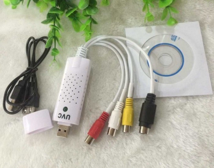
1. UVC video capture card:
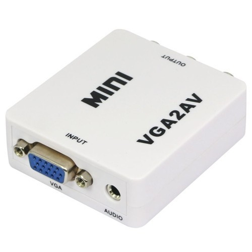
2. VGA to AV Converter:
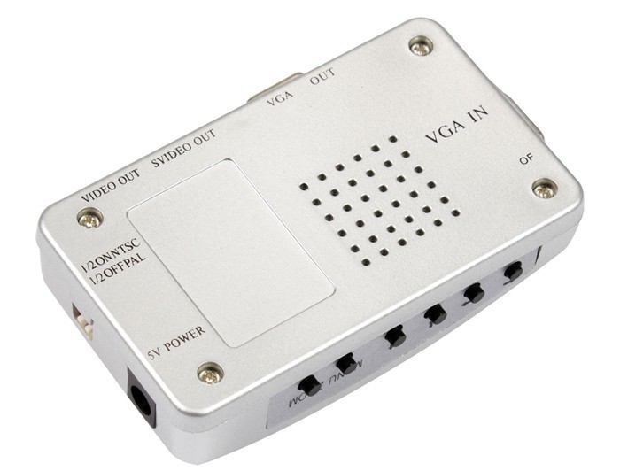
Experimented with another converter, with this:
But the miracle did not happen, the video quality did not improve, but even vice versa.
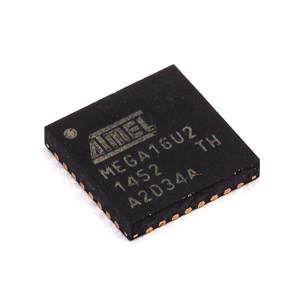
3. Atmega16u2:
4. Orange PI in my case, Orange pi PC model:
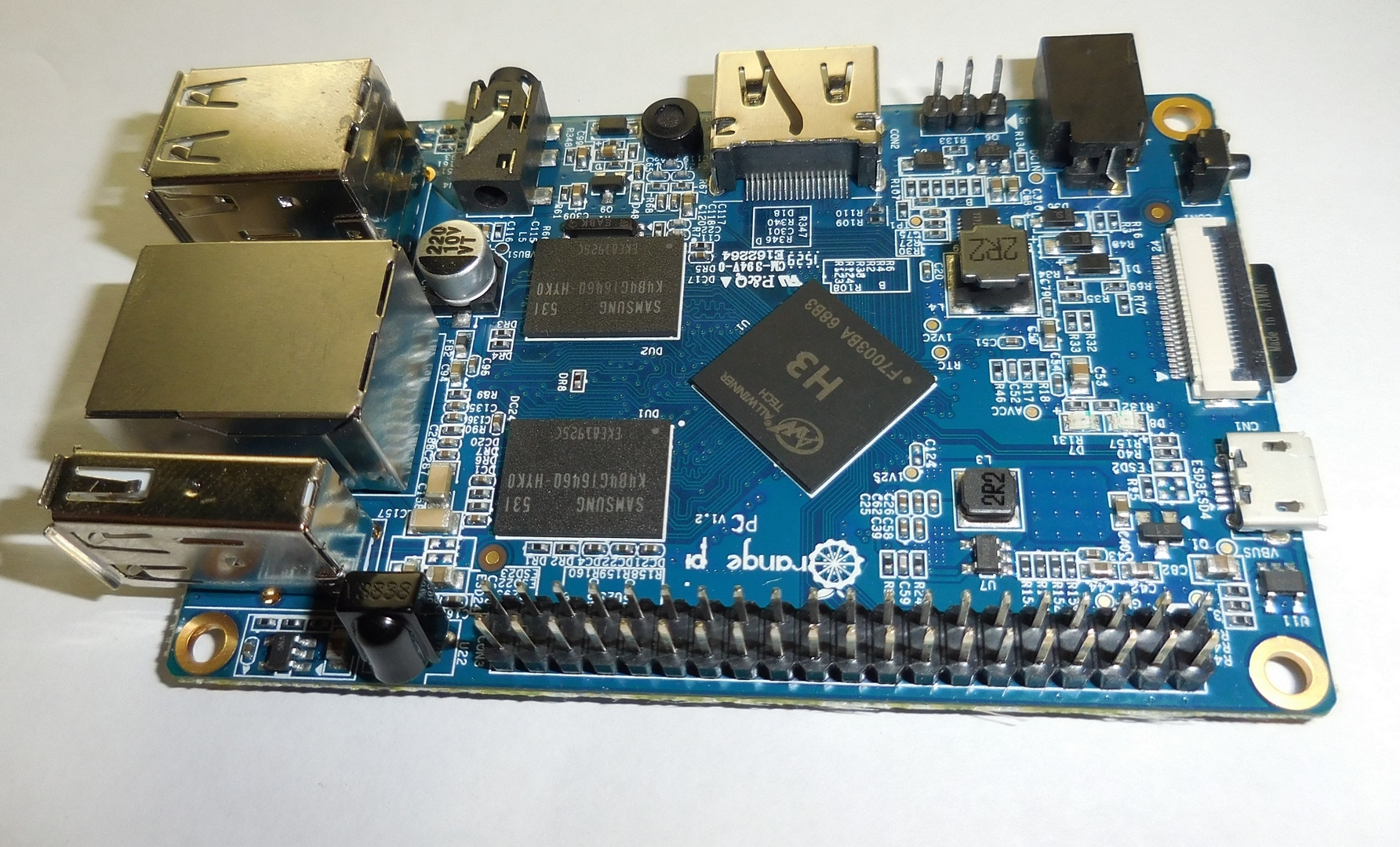
A few words about this micro computer. It is based on the Allwinner H3 processor (a good cheap 4-core processor based on the AWP architecture), 1 gigabyte of RAM, 3 USB, HDMI and so on, a full description is not difficult to find on the Internet.
Here is a link to the forum, this forum thread has a lot of useful information, only of course everything is in English, we are interested in the OrangePI-PC_Ubuntu_Vivid_Mate.img distribution, you can download it from mega.nz or Google Drive. We find in the header the line Download from Mega or Google Drive, click on the link, download.
The procedure for transferring an image to a USB flash drive is the same as for raskberry, on Windows you can use win32 disk imager writer on Linux with the dd command.
A small digression. Orange pi and similar microcomputers built on Allwinner’s Chinese processors are quite inferior to the razberberry not in hardware (hardware), but in software (software), more precisely in OS capabilities and “completeness”, so to speak. A stripped-down kernel, not an optimized file system, a huge number of bugs, this is far from all the problems. This situation arose due to the fact that the processor manufacturer initially focused on tablets (maybe even smartphones) running Android, and from the manufacturer’s point of view, there was apparently no economic feasibility in a full Linux distribution. The Linux kernel was cut down for the very tomatoes, from a full life turned into a vegetable, capable of only primitive actions. For a long time there were Linux distributions on the kernel from the android,
But back to our sheep. The distribution is recorded, the system is running.
Go to the console. User
Update packages:
All settings as in the previous article:
The console is not closing yet.
To transfer control, we will write a program, everything will be described in more detail below, in the meantime we will make the basic preparations.
We install everything necessary for compilation, our program will be in C:
We install the ncurses library, with it we will capture the key values:
We make ourselves the owner of the serial port so that we can write:
Open the kernel module load config config in the editor:
Uncomment the line
Edit autorun:
Add the
In theory, it’s more correct to create a group, assign rights, add a user to the group, but this is all a demo model therefore (I recall a character from a well-known cartoon), and so it goes. Of course, I in no way forbid you to do everything as it should.
Save the changes and reboot:
Let's digress a bit on the hardware.
To transfer control, it was decided to use the Atmega16u2 chip directly without the participation of extra microcontrollers and ArduinoIDE, and we will run the executable code, you guessed it, right on the microcomputer.
We will analyze the logic of the arduins in the previous article.
The key values were sent through the serial port to the Atmega328p microcontroller (a large oblong chip on the Arduino UNO) which from the arrays specified in HIDKeyboard.h transmitted the key codes, the so-called “USB HID keyboard keycodes” to the Atmega16u2 microcontroller (again via the serial port) which sent via USB to the target computer. Serial → Atmega328p → Serial → Atmega16u2 → USB
In general, Atmega328p played the role of an intermediary, and of course it’s logical to remove it, which we will do, for this we’ll rewrite the code that was for arduines under Orangepi, and we will connect Atmega16u2 directly.
Naturally, a bare microcircuit cannot be used; at least a minimal binding is needed.
I advise you to read the review on this link. For our purposes, the USB-powered option is perfect.
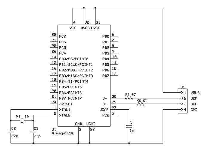
As you can see, the beginner can handle it very easily, there are not many elements that can be dispensed with by hinged installation, it’s better to fix the crystal oscillator so that it does not hang in the air. The generator by the way should be 16 megahertz if it is suddenly not clear from the circuit. And do not pay attention to the fact that the circuit for ATmega32u2 is suitable for ATmega16u2 and for ATmega8u2 as well.
If you have an Arduino UNO board, you can use it, you should connect to the contacts tx - No. 0, rx - No. 1 and it is advisable to remove the Atmega328p mikruha so that it would not consume power in vain and do not clog the serial port ether.
I do not need to remind about logic levels, everything is the same as in the previous article, serial port Orange PI works similarly to Raspberry PI at 3.3 volts and voltage matching is necessary.
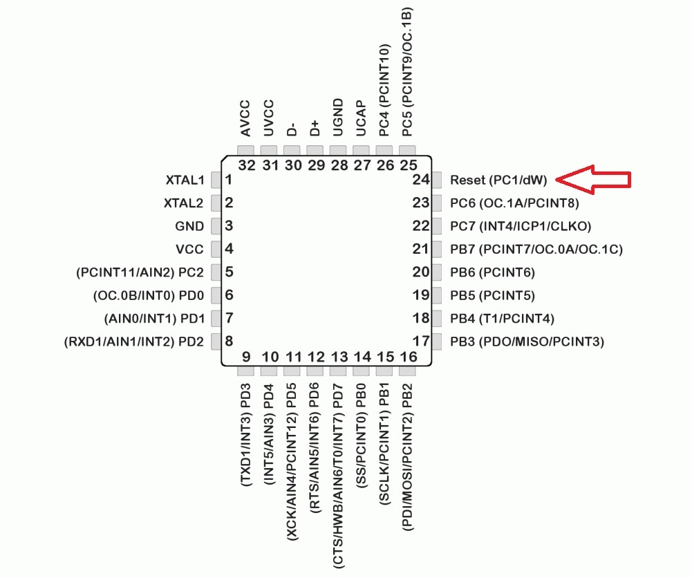
For ATmega16u2 firmware, you need to close the Reset leg with the ground for a second and fill the firmware with Flip program
I will not describe in detail, it was already the last time. On this preparation is over, let's get down to business.
To transfer keys and remotely control the converter, we will write a small program.
At first there was a rush to just port the source from UNO-HIDKeyboard-Library, this is the library for the Arduino IDE (HIDKeyboard.cpp and HIDKeyboard.h files) that was used last time, but the functionality was not enough for the idea, so why not write your own program.
I present to you Linux-Remote-HIDKeyboard, the name is so-so, but you had to call it something, hereinafter referred to as LRHIDKeyboard.cpp or rkeysend (compiled binary).
The source code will consist of 2 files LRHIDKeyboard.cpp and HIDKeyboard.h. HIDKeyboard.h is the same header file from the UNO-HIDKeyboard-Library. Arrays are stored in this file for conversion to “USB HID keyboard keycodes”, only I took the liberty of correcting errors and expanding arrays, the compatibility with HIDKeyboard.cpp was preserved, so that if necessary it can be used for arduins.
USB HID keyboard keycodes - these are the keys of keys transmitted via USB, in details it is possible to read here (pdf).
In the header file HIDKeyboard.h, there are two arrays, the first one for defining regular keys, the second for shift-pressed keys. The decimal number obtained during capture from the terminal is compared with the number of the array element and replaced with this element that looks something like “0x7f” (hexadecimal number). For example, the “a” key has the value “4” in decimal or “04” in hexadecimal, the “ESCAPE” key is “41” in decimal or “29” in hexadecimal, a hexadecimal number is sent to the microcircuit to indicate pressing a key.
Open the Orangepi console, create a directory where the program will be stored, for example like this:
Create files
Open in the HIDKeyboard.h editor:
Copy the contents of the listing:
save Ctrl + x, y, Enter
And again:
Copy the contents of the listing:
Save Ctrl + x, y, Enter.
rkeysend is the name of the executable file obtained during compilation — the
lncurses connection when compiling the ncurses library, is used to capture keys in a terminal and send text messages to the same terminal.
If the compilation was successful, you can proceed to the GPIO ports.
A “freshly compiled” program can not only transfer keys, but also control the converter. I will explain why. Firstly, you can adjust the image, brightness, contrast, sharpness, etc. Secondly, I already wrote about the resolution of the image received from the converter = 720x576. So, the converter has a mode of displaying only part of the image, while the resolution does not change, in other words, you can consider more small details of the image using this mode.
The converter will be controlled by GPIO. GPIO as of course you already know general-purpose input / output, or if in Russian, I liked the rather accurate definition from the Wikipedia “general-purpose input / output interface” a kind of way the microcomputer interacts with the outside world.
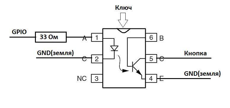
And so we connect the converter with GPIO. There are physical control buttons on the converter: left, right, bottom, top, menu and zoom. They are connected according to the following principle as in the picture. The illustration only shows how the buttons work.
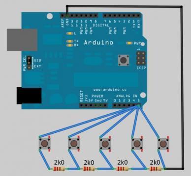
The converter has a port on which it measures voltage and, in accordance with the desired level, performs an action: opens a menu, enlarges an image, moves an image, etc.
To control the buttons, I used bipolar transistors with an optical input AOT128A:
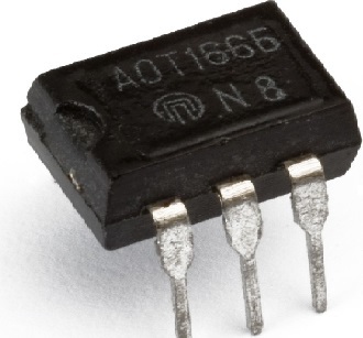
The emitter and collector of the transistor are soldered to the ground and to the contact of the button. We connect (solder) the cathode of the transistor to ground. The anode of the transistor is connected to the desired GPIO port through a 33 Ohm resistor.
If you change something, remember:
The control voltage at the anode of this transistor is no more than 1.6V, when this value is exceeded, the transistor starts to heat up very much and thermal breakdown can occur. It is advisable to use the same power supply for Orangepi and for the converter, otherwise the picture may change due to the potential difference.
We connect the transistor anodes to the following GPIO ports: PA14 - menu, PD14 - zoom, PC4 - top, PC7 - bottom, PG8 - left, PA21- right.
The serial port for connecting the ATmega16u2 chip is located on Ports 11 (RX) and 13 (TX). Connect as indicated in the image.
Now everything is connected. At first I wanted to control the converter on one field-effect transistor using a single port, but somehow it did not work out, the PWM pulsation is transmitted to the transistor and as a result, the resistance starts to float on it, there are options for smoothing filter circuits, but this would greatly complicate the design. There is still an option to use a digital potentiometer via SPI or I2C, everything is already in your hands, go for it.
Check if everything is connected as it should:
Ha Orangepi we launch the compiled program, inscriptions should appear indicating the open serial port and key combinations. Something like that.
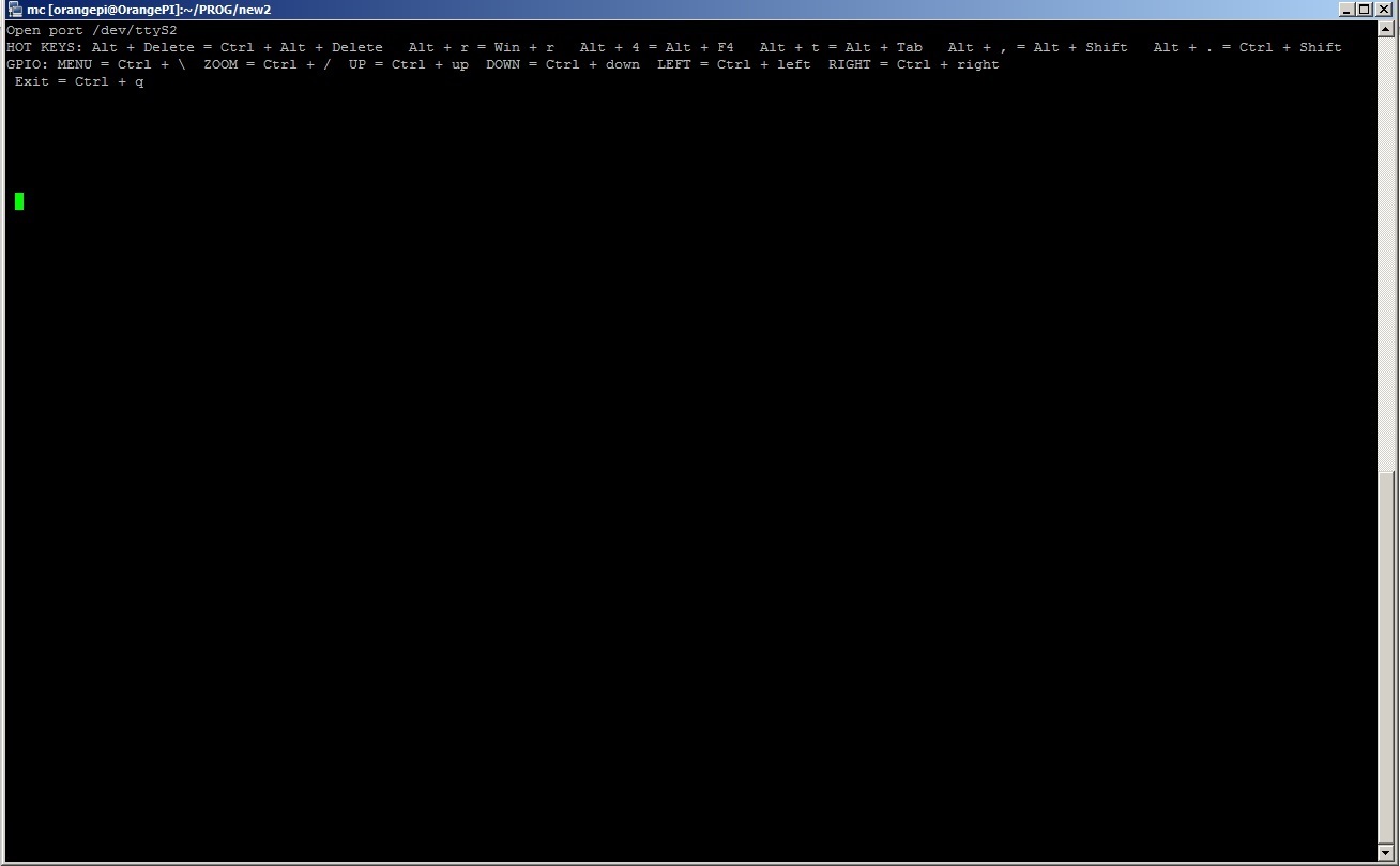
There are keyboard shortcuts for calling the task manager or changing the layout, for example, to press “Ctrl + Alt + Del” in the terminal you need to enter “Alt + Del”, possible combinations are written when the program starts from the top of the terminal window.
The video, as in the previous article, broadcasts motion, is available at
The video remained of very poor quality due to the fact that it is transmitted via the AV input, but now we have remote control of the converter and if you select the desired item in the menu, you can watch the screen in parts in the same resolution.
There are possible solutions to the problem with video quality, only they have one big drawback: the price:
1. Velocap U2m usb 2.0 hdmi
2. UVC USB 3.0 HDMI
I did not try these options, because it’s expensive, maybe someone who reads the article will risk it.
You can probably save on the microcomputer board to change Orangepi PC to Orangepi one or Orangepi Zero, its cost is about 500 rubles. But there may be problems with Orangepi Zero, there is a different processor, respectively, a different distribution with a different kernel, which may not have the necessary drivers and modules. The GPIO potential is not fully disclosed, for example, you can also connect a relay to close the Power and Reset contacts on the motherboard.
VGA to AV converter is approximately 700 rubles.
The video capture card is approximately 500 rubles.
Orangepi PC about 1000rub.
ATmega8U2 / 16U2 / 32U2 about 150rub.
Total: 2350 rub.
Well, this article has come to an end, thanks to everyone who read it. I hope in practice you will succeed. Although I was not able to carry out everything I had planned, the result was interesting, especially for such a price. Of course, the resulting device requires refinement, but I think it still has a right to exist. I give all my best practices as is, without any guarantees, in good hands. Thanks for attention!
Looking at the resulting bike, the idea came up, to fix as many disadvantages as possible. Namely:
- Extend remote management capabilities
- reduce cost;
- to come up with something to transmit the video so that it would be at least a little more comfortable to work remotely.
I’ll say right away that it didn’t work out anything special from the video, we’ll have to be content with what we have, but we won’t talk about sad things.
And so we proceed, with clean hands, a cold head and a warm heart. The components have changed dramatically instead of Raspberry PI we will use Orange PI and instead of Arduino UNO only the very chip (Atmega16u2) that was discussed in the previous article.
The number of components has not changed:
1. UVC video capture card:
2. VGA to AV Converter:
Experimented with another converter, with this:
But the miracle did not happen, the video quality did not improve, but even vice versa.
3. Atmega16u2:
4. Orange PI in my case, Orange pi PC model:
A few words about this micro computer. It is based on the Allwinner H3 processor (a good cheap 4-core processor based on the AWP architecture), 1 gigabyte of RAM, 3 USB, HDMI and so on, a full description is not difficult to find on the Internet.
Preparatory stage
Install the operating system on Orangepi
Here is a link to the forum, this forum thread has a lot of useful information, only of course everything is in English, we are interested in the OrangePI-PC_Ubuntu_Vivid_Mate.img distribution, you can download it from mega.nz or Google Drive. We find in the header the line Download from Mega or Google Drive, click on the link, download.
The procedure for transferring an image to a USB flash drive is the same as for raskberry, on Windows you can use win32 disk imager writer on Linux with the dd command.
A small digression. Orange pi and similar microcomputers built on Allwinner’s Chinese processors are quite inferior to the razberberry not in hardware (hardware), but in software (software), more precisely in OS capabilities and “completeness”, so to speak. A stripped-down kernel, not an optimized file system, a huge number of bugs, this is far from all the problems. This situation arose due to the fact that the processor manufacturer initially focused on tablets (maybe even smartphones) running Android, and from the manufacturer’s point of view, there was apparently no economic feasibility in a full Linux distribution. The Linux kernel was cut down for the very tomatoes, from a full life turned into a vegetable, capable of only primitive actions. For a long time there were Linux distributions on the kernel from the android,
But back to our sheep. The distribution is recorded, the system is running.
Customize motion
Go to the console. User
orangepior rootpassword orangepiUpdate packages:
sudo apt-get update && sudo apt-get upgrade –yInstall motion
All settings as in the previous article:
Fragment of the article
Edit autorun config:
In the line
We edit the config of motion itself (a):
Change the parameter values as follows:
The parameter determines the launch of the application as a service:
These parameters determine the resolution of the transmitted image, it makes no sense to set a higher resolution, because video capture is limited to PAL or SECAM standards, the resolution of which is 720x576. This is by the way an annoying flaw, but more on that later.
Frame Rate:
Disable saving screenshots:
Image Transmission Quality:
Frame Rate:
Removing restrictions on connecting from other ip
Save the changes Ctrl + x, y, Enter.
sudo apt-get install motion -yEdit autorun config:
sudo nano /etc/default/motionIn the line
start_motion_daemonwe put 'yes'. Save the changes Ctrl + x, y, Enter. We edit the config of motion itself (a):
sudo nano /etc/motion/motion.confChange the parameter values as follows:
The parameter determines the launch of the application as a service:
daemon onThese parameters determine the resolution of the transmitted image, it makes no sense to set a higher resolution, because video capture is limited to PAL or SECAM standards, the resolution of which is 720x576. This is by the way an annoying flaw, but more on that later.
width 800
height 600
Frame Rate:
framerate 25Disable saving screenshots:
output_normal offImage Transmission Quality:
webcam_quality 100Frame Rate:
webcam_maxrate 25Removing restrictions on connecting from other ip
webcam_localhost offSave the changes Ctrl + x, y, Enter.
The console is not closing yet.
Compilation preparation
To transfer control, we will write a program, everything will be described in more detail below, in the meantime we will make the basic preparations.
We install everything necessary for compilation, our program will be in C:
sudo apt-get install build-essential -yWe install the ncurses library, with it we will capture the key values:
sudo apt-get install ncurses -yWe make ourselves the owner of the serial port so that we can write:
sudo chown orangepi /dev/ttyS2Open the kernel module load config config in the editor:
sudo nano /etc/modulesUncomment the line
gpio-sunxi. With this action, we activate gpio, or rather a module for working with it, why I will tell you later. Edit autorun:
sudo nano /etc/rc.localAdd the
exitfollowing before the line chown -R orangepi /sys/devices/platform/*. This command will make the orangepi user the owner of the virtual files that are responsible for interacting with the GPIO port. In theory, it’s more correct to create a group, assign rights, add a user to the group, but this is all a demo model therefore (I recall a character from a well-known cartoon), and so it goes. Of course, I in no way forbid you to do everything as it should.
Save the changes and reboot:
sudo rebootLet's digress a bit on the hardware.
Atmega16u2
To transfer control, it was decided to use the Atmega16u2 chip directly without the participation of extra microcontrollers and ArduinoIDE, and we will run the executable code, you guessed it, right on the microcomputer.
We will analyze the logic of the arduins in the previous article.
The key values were sent through the serial port to the Atmega328p microcontroller (a large oblong chip on the Arduino UNO) which from the arrays specified in HIDKeyboard.h transmitted the key codes, the so-called “USB HID keyboard keycodes” to the Atmega16u2 microcontroller (again via the serial port) which sent via USB to the target computer. Serial → Atmega328p → Serial → Atmega16u2 → USB
In general, Atmega328p played the role of an intermediary, and of course it’s logical to remove it, which we will do, for this we’ll rewrite the code that was for arduines under Orangepi, and we will connect Atmega16u2 directly.
Naturally, a bare microcircuit cannot be used; at least a minimal binding is needed.
I advise you to read the review on this link. For our purposes, the USB-powered option is perfect.
As you can see, the beginner can handle it very easily, there are not many elements that can be dispensed with by hinged installation, it’s better to fix the crystal oscillator so that it does not hang in the air. The generator by the way should be 16 megahertz if it is suddenly not clear from the circuit. And do not pay attention to the fact that the circuit for ATmega32u2 is suitable for ATmega16u2 and for ATmega8u2 as well.
If you have an Arduino UNO board, you can use it, you should connect to the contacts tx - No. 0, rx - No. 1 and it is advisable to remove the Atmega328p mikruha so that it would not consume power in vain and do not clog the serial port ether.
I do not need to remind about logic levels, everything is the same as in the previous article, serial port Orange PI works similarly to Raspberry PI at 3.3 volts and voltage matching is necessary.
For ATmega16u2 firmware, you need to close the Reset leg with the ground for a second and fill the firmware with Flip program
I will not describe in detail, it was already the last time. On this preparation is over, let's get down to business.
Writing a program
To transfer keys and remotely control the converter, we will write a small program.
Theory
At first there was a rush to just port the source from UNO-HIDKeyboard-Library, this is the library for the Arduino IDE (HIDKeyboard.cpp and HIDKeyboard.h files) that was used last time, but the functionality was not enough for the idea, so why not write your own program.
I present to you Linux-Remote-HIDKeyboard, the name is so-so, but you had to call it something, hereinafter referred to as LRHIDKeyboard.cpp or rkeysend (compiled binary).
The source code will consist of 2 files LRHIDKeyboard.cpp and HIDKeyboard.h. HIDKeyboard.h is the same header file from the UNO-HIDKeyboard-Library. Arrays are stored in this file for conversion to “USB HID keyboard keycodes”, only I took the liberty of correcting errors and expanding arrays, the compatibility with HIDKeyboard.cpp was preserved, so that if necessary it can be used for arduins.
USB HID keyboard keycodes - these are the keys of keys transmitted via USB, in details it is possible to read here (pdf).
In the header file HIDKeyboard.h, there are two arrays, the first one for defining regular keys, the second for shift-pressed keys. The decimal number obtained during capture from the terminal is compared with the number of the array element and replaced with this element that looks something like “0x7f” (hexadecimal number). For example, the “a” key has the value “4” in decimal or “04” in hexadecimal, the “ESCAPE” key is “41” in decimal or “29” in hexadecimal, a hexadecimal number is sent to the microcircuit to indicate pressing a key.
Practice
Open the Orangepi console, create a directory where the program will be stored, for example like this:
cd ~
mkdir PROG
cd PROG
Create files
HIDKeyboard.hand LRHIDKeyboard.cpp:touch HIDKeyboard.h
touch LRHIDKeyboard.cppOpen in the HIDKeyboard.h editor:
nano HIDKeyboard.hCopy the contents of the listing:
Listing HIDKeyboard.h
#ifndef HIDKeyboard_h
#define HIDKeyboard_h
//#include "Arduino.h"
/****************************************************************************
 * SPECIAL CHARACTER DEFINES
 *
 * These are the HID values for keys that do not output characters
 *
 ****************************************************************************/
// HID Values of Function Keys
#define F1 0x3a
#define F2 0x3b
#define F3 0x3c
#define F4 0x3d
#define F5 0x3e
#define F6 0x3f
#define F7 0x40
#define F8 0x41
#define F9 0x42
#define F10 0x43
#define F11 0x44
#define F12 0x45
// HID Values of Special Keys
#define ENTER 0x28
#define ESCAPE 0x29
#define BACKSPACE 0x2a
#define TAB 0x2b
#define SPACEBAR 0x2c
#define CAPSLOCK 0x39
#define PRINTSCREEN 0x46
#define SCROLLLOCK 0x47
#define PAUSE 0x48
#define INSERT 0x49
#define HOME 0x4a
#define PAGEUP 0x4b
#define DELETE 0x4c
#define END 0x4d
#define PAGEDOWN 0x4e
#define RIGHTARROW 0x4f
#define LEFTARROW 0x50
#define DOWNARROW 0x51
#define UPARROW 0x52
// HID Values of Keypad Keys
#define NUMLOCK 0x53
#define KEYPADSLASH 0x54
#define KEYPADSTAR 0x55
#define KEYPADMINUS 0x56
#define KEYPADPLUS 0x57
#define KEYPADENTER 0x58
#define KEYPAD1 0x59
#define KEYPAD2 0x5a
#define KEYPAD3 0x5b
#define KEYPAD4 0x5c
#define KEYPAD5 0x5d
#define KEYPAD6 0x5e
#define KEYPAD7 0x5f
#define KEYPAD8 0x60
#define KEYPAD9 0x61
#define KEYPAD0 0x62
#define KEYPADPERIOD 0x63
// HID Values of System Keys
#define KEYBOARDAPPLICATION 0x65
#define KEYBOARDPOWER 0x66
#define VOLUMEMUTE 0x7f
#define VOLUMEUP 0x80
#define VOLUMEDOWN 0x81
// Common-use modifiers
#define LCTRL 0x01
#define SHIFT 0x02
#define ALT 0x04
#define GUI 0x08
/****************************************************************************
 *
 * ASCII->HID LOOKUP TABLE
 *
 *	Taken from the HID Table definition at
 * 		http://www.usb.org/developers/devclass_docs/Hut1_11.pdf
 *
 *  This array maps the ASCII value of a type-able character to its
 *  corresponding HID value.
 *
 *	Example:
 *		'a' = ASCII value 97 = HID value 0x04
 * 		HIDTable['a'] = HIDTable[97] = 0x04
 *
 * 	NOTE:
 *		"Shift Modified" HID values are the same as the non Shift-Modified values
 * 		for any given character, e.g. the HID value for '2' is equal to the
 *		HID value for '@'. The Shift-Modified value is sent by setting the
 *		modifier value (buf[0]) to the corresponding modifier value in the
 *    modifier table.
 *
 ****************************************************************************/
const static uint8_t HIDTable[] =  {
0x00, // 0
0x00, 0x00, 0x00, 0x00, 0x00, 0x00, 0x00, 0x2A, 0x2b, 0x28, // 10
0x00, 0x00, 0x28, 0x00, 0x00, 0x00, 0x00, 0x00, 0x00, 0x00, // 20
0x00, 0x00, 0x00, 0x00, 0x00, 0x00, 0x29, 0x00, 0x00, 0x00, // 30
0x00, 0x2c, 0x1e, 0x34, 0x20, 0x21, 0x22, 0x24, 0x34, 0x26, // 40
0x27, 0x25, 0x2e, 0x36, 0x2d, 0x37, 0x38, 0x27, 0x1e, 0x1f, // 50
0x20, 0x21, 0x22, 0x23, 0x24, 0x25, 0x26, 0x33, 0x33, 0x36, // 60
0x2e, 0x37, 0x38, 0x1f, 0x04, 0x05, 0x06, 0x07, 0x08, 0x09, // 70
0x0a, 0x0b, 0x0c, 0x0d, 0x0e, 0x0f, 0x10, 0x11, 0x12, 0x13, // 80
0x14, 0x15, 0x16, 0x17, 0x18, 0x19, 0x1a, 0x1b, 0x1c, 0x1d, // 90
0x2f, 0x31, 0x30, 0x23, 0x2d, 0x35, 0x04, 0x05, 0x06, 0x07, // 100
0x08, 0x09, 0x0a, 0x0b, 0x0c, 0x0d, 0x0e, 0x0f, 0x10, 0x11, // 110
0x12, 0x13, 0x14, 0x15, 0x16, 0x17, 0x18, 0x19, 0x1a, 0x1b, // 120
0x1c, 0x1d, 0x2f, 0x31, 0x30, 0x35, 0x4c, 0x00, 0x00, 0x00, // 130
0x00, 0x00, 0x00, 0x00, 0x00, 0x00, 0x00, 0x00, 0x00, 0x00, // 140
0x00, 0x00, 0x00, 0x00, 0x00, 0x00, 0x00, 0x00, 0x00, 0x00, // 150
0x00, 0x00, 0x00, 0x00, 0x00, 0x00, 0x00, 0x00, 0x00, 0x00, // 160
0x00, 0x00, 0x00, 0x00, 0x00, 0x00, 0x00, 0x00, 0x00, 0x00, // 170
0x00, 0x00, 0x00, 0x00, 0x00, 0x00, 0x00, 0x00, 0x00, 0x00, // 180
0x00, 0x00, 0x00, 0x00, 0x00, 0x00, 0x00, 0x00, 0x00, 0x00, // 190
0x00, 0x00, 0x00, 0x00, 0x00, 0x00, 0x00, 0x00, 0x00, 0x00, // 200
0x00, 0x00, 0x00, 0x00, 0x00, 0x00, 0x00, 0x00, 0x00, 0x00, // 210
0x00, 0x00, 0x00, 0x00, 0x00, 0x00, 0x00, 0x00, 0x00, 0x00, // 220
0x00, 0x00, 0x00, 0x00, 0x00, 0x00, 0x00, 0x00, 0x00, 0x00, // 230
0x00, 0x00, 0x00, 0x00, 0x00, 0x00, 0x00, 0x00, 0x00, 0x00, // 240
0x00, 0x00, 0x00, 0x00, 0x00, 0x00, 0x00, 0x00, 0x00, 0x00, // 250
0x00, 0x00, 0x00, 0x00, 0x00, 0x00, 0x00, 0x51, 0x52, 0x50, // 260
0x4f, 0x4a, 0x2a, 0x00, 0x3a, 0x3b, 0x3c, 0x3d, 0x3e, 0x3f, // 270
0x40, 0x41, 0x42, 0x43, 0x44, 0x45, 0x00, 0x00, 0x00, 0x00, // 280
0x00, 0x00, 0x00, 0x00, 0x00, 0x00, 0x00, 0x00, 0x00, 0x00, // 290
0x00, 0x00, 0x00, 0x00, 0x00, 0x00, 0x00, 0x00, 0x00, 0x00, // 300
0x00, 0x00, 0x00, 0x00, 0x00, 0x00, 0x00, 0x00, 0x00, 0x00, // 310
0x00, 0x00, 0x00, 0x00, 0x00, 0x00, 0x00, 0x00, 0x00, 0x00, // 320
0x00, 0x00, 0x00, 0x00, 0x00, 0x00, 0x00, 0x00, 0x00, 0x4c, // 330
0x49, 0x00, 0x00, 0x00, 0x00, 0x00, 0x00, 0x4e, 0x4b, 0x00, // 340
0x00, 0x00, 0x00, 0x00, 0x00, 0x00, 0x00, 0x00, 0x00, 0x00, // 350
0x00, 0x00, 0x00, 0x00, 0x00, 0x00, 0x00, 0x00, 0x00, 0x4d, // 360
};
/****************************************************************************
 *
 * ASCII->MODIFIER LOOKUP TABLE
 *
 * 	Looks up whether or not the HID report should use the SHIFT modifier.
 *
 * 	Example:
 *		The character '2' and the character '@' have different ASCII values but
 * 		the same HID value. This table uses the ASCII value to determine if
 *		we should hold shift while sending the key. e.g.:
 *
 *			HIDTable['2'] = 0x1f  and  modifierTable['2'] = 0
 *			HIDTable['@'] = 0x1f  and  modifierTable['@'] = SHIFT
 *
 *  There's probaly a better way to do this, but it's functional.
 *
 ****************************************************************************/
const static uint8_t modifierTable[] = {
0x00, // 0
 0x00, 0x00, 0x00, 0x00, 0x00, 0x00, 0x00, 0x00, 0x00, 0x00, 					// 10
 0x00, 0x00, 0x00, 0x00, 0x00, 0x00, 0x00, 0x00, 0x00, 0x00, 					// 20
 0x00, 0x00, 0x00, 0x00, 0x00, 0x00, 0x00, 0x00, 0x00, 0x00, 					// 30
 0x00, 0x00, SHIFT, SHIFT, SHIFT, SHIFT, SHIFT, SHIFT, 0x00, SHIFT, 	// 40
 SHIFT, SHIFT, SHIFT, 0x00, 0x00, 0x00, 0x00, 0x00, 0x00, 0x00, 				// 50
 0x00, 0x00, 0x00, 0x00, 0x00, 0x00, 0x00, SHIFT, 0x00, SHIFT, 				// 60
 0x00, SHIFT, SHIFT, SHIFT, SHIFT, SHIFT, SHIFT, SHIFT, SHIFT, SHIFT, 	// 70
 SHIFT, SHIFT, SHIFT, SHIFT, SHIFT, SHIFT, SHIFT, SHIFT, SHIFT, SHIFT, // 80
 SHIFT, SHIFT, SHIFT, SHIFT, SHIFT, SHIFT, SHIFT, SHIFT, SHIFT, SHIFT, // 90
 0x00, 0x00, 0x00, SHIFT, SHIFT, 0x00, 0x00, 0x00, 0x00, 0x00, 				// 100
 0x00, 0x00, 0x00, 0x00, 0x00, 0x00, 0x00, 0x00, 0x00, 0x00, 					// 110
 0x00, 0x00, 0x00, 0x00, 0x00, 0x00, 0x00, 0x00, 0x00, 0x00, 					// 120
 0x00, 0x00, SHIFT, SHIFT, SHIFT, SHIFT, 0x00 // 127
};
class HIDKeyboard
{
	public:
		// Constructor
		HIDKeyboard();
		// Public functions
		void begin(); // Starts the required serial communication (9600 baud)
		void pressKey(uint8_t modifier, uint8_t key); // Looks up key in HIDTable and sends with a modifier
		void pressKey(uint8_t key); // Sends key report without modifier (modifier = 0)
		void pressSpecialKey(uint8_t modifier, uint8_t specialKey); // Sends specialKey with a modifier
		void pressSpecialKey(uint8_t specialKey); // Sends specialKey without modifier
		void releaseKey(); // Releases keys (clears key and modifier)
		void print(char* sequence); // Prints string
		void println(char* sequence); // Prints string  followed by a carriage return
	private:
		// HID report buffer
		uint8_t buf[8]; // In report, buf[0] = modifier and buf[2] = key HID value
};
#endif
save Ctrl + x, y, Enter
And again:
nano LRHIDKeyboard.cppCopy the contents of the listing:
Listing LRHIDKeyboard.cpp
#include
#include
#include
#include
#include
#include
#include
#include
#include
#include "HIDKeyboard.h"
char myport[] = "/dev/ttyS2"; //указываем нужный serial port можно менять прямо тут
//использование кнопок управлениея конвертером можно менять прямо тут
char nul[] = "";
char menu[] = "/sys/class/gpio_sw/PA14/data"; //меню
char zoom[] = "/sys/class/gpio_sw/PD14/data"; //зуум
char kup[] = "/sys/class/gpio_sw/PC4/data"; //верх
char kdn[] = "/sys/class/gpio_sw/PC7/data"; //низ
char klf[] = "/sys/class/gpio_sw/PG8/data"; //лево
char krt[] = "/sys/class/gpio_sw/PA21/data"; //право
uint8_t buf[8] = {
	0 }; /* Keyboard report buffer */
int open_port(char *devname) //открываем serial port
{
  int fd;
  fd = open(devname, O_RDWR | O_NOCTTY | O_NDELAY);
  if(fd == -1) //проверка
  {
    printw("Port is not open! %s" , devname);
    return -1;
  }
  else
  {
    fcntl(fd, F_SETFL, 0);
    printw("Open port %s", devname);
  }
//настройка порта
  struct termios port_settings;
  cfsetispeed(&port_settings, B9600);
  cfsetospeed(&port_settings, B9600);
  port_settings.c_cflag &= ~PARENB;
  port_settings.c_cflag &= ~CSTOPB;
  port_settings.c_cflag &= ~CSIZE;
  port_settings.c_cflag |= CS8;
  tcsetattr(fd, TCSANOW, &port_settings);
  return(fd);
}
int alt_check(int check) //Если последовательность с ALT, возвращает символ следующий за ALT,в противном случае "0"
{
  if(check == 27)
  {
    nodelay(stdscr,TRUE);
    check = getch();
    if (check == -1) return ESCAPE; //Если данных не последовало значит Esc
    nodelay(stdscr,FALSE);
    return check;
  }
  //else return 0;
  return 0;
}
int hot_key(int fd, int alt, int vchar) //комбинации
{
  if(alt != 0)
  {
    if (alt == 330) //Нажато "Alt" + "Delete" отправка Ctrl + Alt + Delete
    {
      vchar = 0;
      buf[0] = 0x04|0x01;
      buf[2] = HIDTable[alt];
      write(fd, buf, 8);
      return 0;
    }
    if (alt == 114) //Нажато "Alt" + "r" отправка Win + r
    {
      vchar = 0;
      buf[0] = 0x08;
      buf[2] = HIDTable[alt];
      write(fd, buf, 8);
      return 0;
    }
    if (alt == 52) //Нажато "Alt" + "4" отправка Alt + F4
    {
      vchar = 0;
      buf[0] = 0x04;
      buf[2] = 0x3d;
      write(fd, buf, 8);
      return 0;
    }
    if (alt == 116) //Нажато "Alt" + "t" отправка Alt + Tab
    {
      vchar = 0;
      buf[0] = 0x04;
      buf[2] = 0x2b;
      write(fd, buf, 8);
      return 0;
    }
    if (alt == 44) //Нажато "Alt" + "," отправка Alt + Shift
    {
      vchar = 0;
      buf[0] = 0x04|0x02;
      write(fd, buf, 8);
      return 0;
    }
    if (alt == 46) //Нажато "Alt" + "." отправка Ctrl + Shift
    {
      vchar = 0;
      buf[0] = 0x01|0x02;
      write(fd, buf, 8);
      return 0;
    }
  }
  else
  {
        if (vchar == 17) //выход по нажатию "Ctrl" + "q"
    {
      endwin();
      exit(0);
    }
    //Управление конвертером
    *nul = '\0';
    if (vchar == 28) strcpy(nul, menu); // "Ctrl" + "\"
    if (vchar == 31) strcpy(nul, zoom); // "Ctrl" + "/"
    if (vchar == 566) strcpy(nul, kup); // "Ctrl" + "up"
    if (vchar == 525) strcpy(nul, kdn); // "Ctrl" + "down"
    if (vchar == 545) strcpy(nul, klf); // "Ctrl" + "left"
    if (vchar == 560) strcpy(nul, krt); // "Ctrl" + "right"
    FILE *f = fopen(nul, "w"); //Открываем файл
    if (f != '\0')
    {
      fwrite("1", 1, 1, f);
      int wrt = fclose(f); //Пишем в файл
      usleep(70000);
      if (wrt == 0)
      {
        FILE *f = fopen(nul, "w");
        fwrite("0", 1, 1, f);
        fclose(f);
      }
    else printf("error write file:  %s", nul);
    return 0;
    }
    return vchar;
  }
}
int send_key(int fd, int altkey, int getkey) //Отправка нажатий
{
  if (altkey == ESCAPE)
  {
    buf[0] = 0x00;
    buf[2] = 0x29;
    write(fd, buf, 8);
    return 1;
  }
  if (altkey != 0)
  {
    buf[0] = 0x04;
    buf[2] = HIDTable[altkey];
    write(fd, buf, 8);
    return 1;
  }
  else
  {
    if (getkey == 0) return 0;
    //printf("KEY NAME : %s - %d\n", keyname(getkey),getkey); //Для отладки
    buf[0] = modifierTable[getkey];
    buf[2] = HIDTable[getkey];
    write(fd, buf, 8);
    return 1;
  }
  return(-1);
}
int release_key(int fd) // Отпустить нажатые клавиши
{
  buf[0] = 0;
  buf[2] = 0;
  write(fd, buf, 8);
}
int main(void)
{
  initscr();
  keypad(stdscr,TRUE); //для захвата спец символов
  raw(); //для захвата комбинаций
  int fd = open_port(myport);
  printw("\nHOT KEYS: Alt + Delete = Ctrl + Alt + Delete   Alt + r = Win + r   Alt + 4 = Alt + F4   Alt + t = Alt + Tab   Alt + , = Alt + Shift   Alt + . = Ctrl + Shift");
  printw("\nGPIO: MENU = Ctrl + \\  ZOOM = Ctrl + /  UP = Ctrl + up  DOWN = Ctrl + down  LEFT = Ctrl + left  RIGHT = Ctrl + right");
  printw("\n Exit = Ctrl + q");
  move(10,1);
  refresh();
    while (fd != -1)
    {
      int pkey = getch();
      int alt = alt_check(pkey);
      int hot = hot_key(fd, alt, pkey);
      send_key(fd, alt, hot);
      release_key(fd);
    }
  endwin();
}
Save Ctrl + x, y, Enter.
Compiling
g++ LRHIDKeyboard.cpp -o rkeysend -lncursesrkeysend is the name of the executable file obtained during compilation — the
lncurses connection when compiling the ncurses library, is used to capture keys in a terminal and send text messages to the same terminal.
If the compilation was successful, you can proceed to the GPIO ports.
Converter Management
A “freshly compiled” program can not only transfer keys, but also control the converter. I will explain why. Firstly, you can adjust the image, brightness, contrast, sharpness, etc. Secondly, I already wrote about the resolution of the image received from the converter = 720x576. So, the converter has a mode of displaying only part of the image, while the resolution does not change, in other words, you can consider more small details of the image using this mode.
The converter will be controlled by GPIO. GPIO as of course you already know general-purpose input / output, or if in Russian, I liked the rather accurate definition from the Wikipedia “general-purpose input / output interface” a kind of way the microcomputer interacts with the outside world.
Connect Orangepi PC to the converter
And so we connect the converter with GPIO. There are physical control buttons on the converter: left, right, bottom, top, menu and zoom. They are connected according to the following principle as in the picture. The illustration only shows how the buttons work.
The converter has a port on which it measures voltage and, in accordance with the desired level, performs an action: opens a menu, enlarges an image, moves an image, etc.
To control the buttons, I used bipolar transistors with an optical input AOT128A:
The emitter and collector of the transistor are soldered to the ground and to the contact of the button. We connect (solder) the cathode of the transistor to ground. The anode of the transistor is connected to the desired GPIO port through a 33 Ohm resistor.
If you change something, remember:
The control voltage at the anode of this transistor is no more than 1.6V, when this value is exceeded, the transistor starts to heat up very much and thermal breakdown can occur. It is advisable to use the same power supply for Orangepi and for the converter, otherwise the picture may change due to the potential difference.
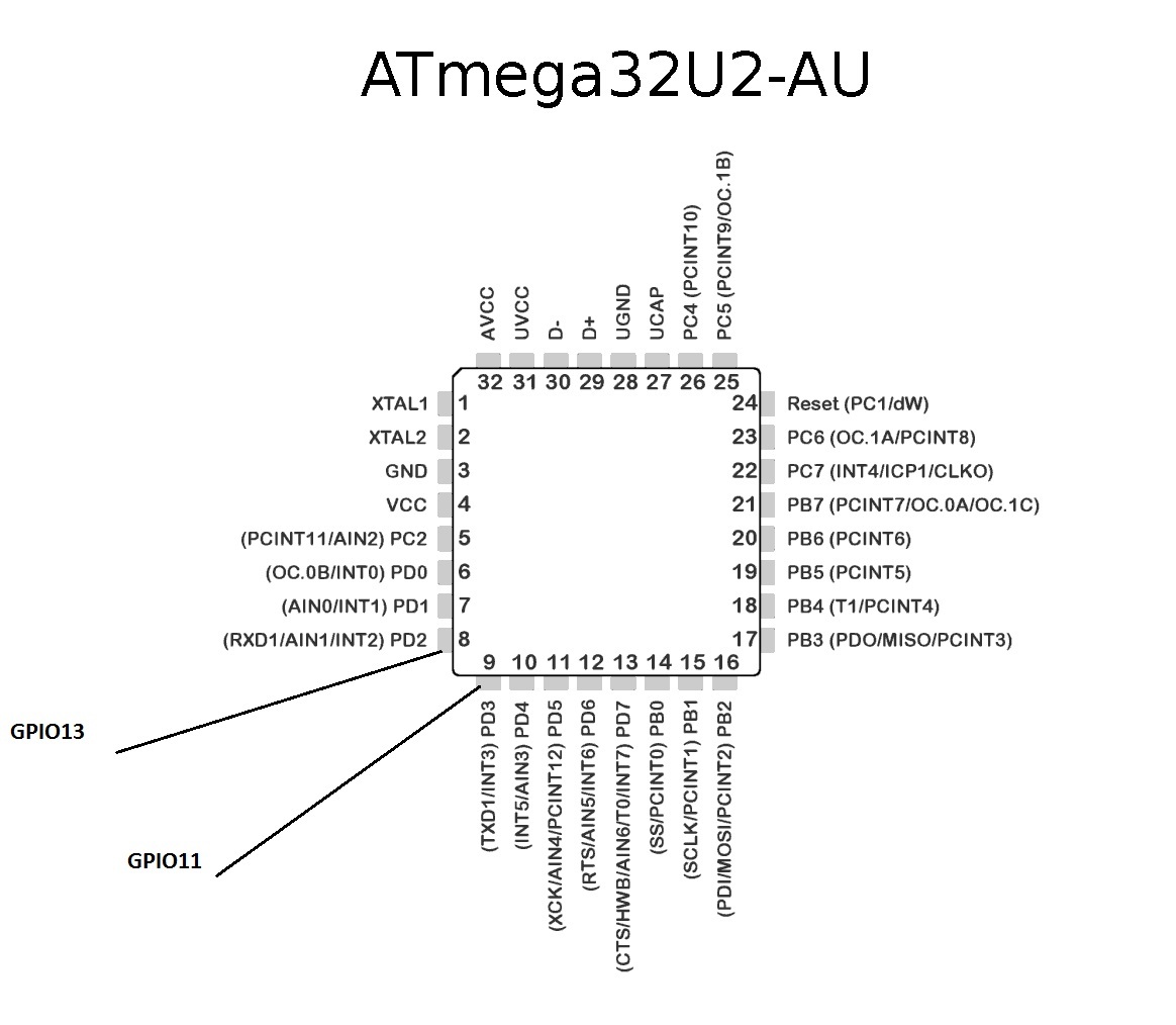
We connect the transistor anodes to the following GPIO ports: PA14 - menu, PD14 - zoom, PC4 - top, PC7 - bottom, PG8 - left, PA21- right.
The serial port for connecting the ATmega16u2 chip is located on Ports 11 (RX) and 13 (TX). Connect as indicated in the image.
Now everything is connected. At first I wanted to control the converter on one field-effect transistor using a single port, but somehow it did not work out, the PWM pulsation is transmitted to the transistor and as a result, the resistance starts to float on it, there are options for smoothing filter circuits, but this would greatly complicate the design. There is still an option to use a digital potentiometer via SPI or I2C, everything is already in your hands, go for it.
Launch
Check if everything is connected as it should:
- Orangepi GPIO to Converter
- VGA to Computer Converter (slave)
- AV output converter to AV input of video capture card
- USBpi USBpi Capture Card
- Orangepi to ATmega8U2 / 16U2 / 32U2 chip
- Chip ATmega8U2 / 16U2 / 32U2 via USB to computer (slave)
- Computer (master) over SSH to Orangepi
Run the program
Ha Orangepi we launch the compiled program, inscriptions should appear indicating the open serial port and key combinations. Something like that.
There are keyboard shortcuts for calling the task manager or changing the layout, for example, to press “Ctrl + Alt + Del” in the terminal you need to enter “Alt + Del”, possible combinations are written when the program starts from the top of the terminal window.
The video, as in the previous article, broadcasts motion, is available at
orangepi:8081. Well, that’s all, all the necessary information for repeating the experience is stated, the mission is completed.To summarize:
Video transfer
The video remained of very poor quality due to the fact that it is transmitted via the AV input, but now we have remote control of the converter and if you select the desired item in the menu, you can watch the screen in parts in the same resolution.
There are possible solutions to the problem with video quality, only they have one big drawback: the price:
1. Velocap U2m usb 2.0 hdmi
2. UVC USB 3.0 HDMI
I did not try these options, because it’s expensive, maybe someone who reads the article will risk it.
You can probably save on the microcomputer board to change Orangepi PC to Orangepi one or Orangepi Zero, its cost is about 500 rubles. But there may be problems with Orangepi Zero, there is a different processor, respectively, a different distribution with a different kernel, which may not have the necessary drivers and modules. The GPIO potential is not fully disclosed, for example, you can also connect a relay to close the Power and Reset contacts on the motherboard.
Cost price
VGA to AV converter is approximately 700 rubles.
The video capture card is approximately 500 rubles.
Orangepi PC about 1000rub.
ATmega8U2 / 16U2 / 32U2 about 150rub.
Total: 2350 rub.
Well, this article has come to an end, thanks to everyone who read it. I hope in practice you will succeed. Although I was not able to carry out everything I had planned, the result was interesting, especially for such a price. Of course, the resulting device requires refinement, but I think it still has a right to exist. I give all my best practices as is, without any guarantees, in good hands. Thanks for attention!