Bridge-domains and virtual-switch in JunOS

About a year ago or earlier, I wrote an article on routing-instance in JunOS, where I described the main types of routing instances, with the exception of virtual switch and evpn. You can read about the latter in an article on EVPN, but virtual-switch has been left unattended for now. Many underestimate the capabilities of this routing instance - but the functionality is decent. In this short article, we will consider what virtual-switch is, what it is eaten with, and whether you need it.
Before proceeding directly to the discussion and configuration of the virtual switch, we need to highlight two very important issues:
1. The method (style) of configuring the tagged interface in JunOS;
2. What is a bridge domain.
JunOS provides us with two methods for configuring a tagged interface intended for use in a bridge domain:
1. Service Provider
2. Enterprise
Let us dwell on them in more detail.
Note: all examples use interfaces with flexible-ethernet-services encapsulation and flexible-vlan-tagging, which gives maximum freedom in configuring interfaces:bormoglotx@RZN-PE1> show configuration interfaces ae3 apply-groups-except CORE; description "to RZN-CE1 | ae0"; flexible-vlan-tagging; encapsulation flexible-ethernet-services; aggregated-ether-options { minimum-links 1; link-speed 1g; lacp { active; periodic fast;
Service Provider
This method of configuring the interface gives us complete freedom in manipulating vlan tags, which uses the pop (uninstall), push (add), swap (replace) tag operations, as well as operations with two tags, for example pop-swap removes the top tag and replacing the bottom when using double tagging. The easiest way to use this method of creating a tagged interface is as follows:
[edit]
bormoglotx@RZN-PE1# show interfaces ae3.10
encapsulation vlan-bridge;
vlan-id 10;
This is a simple tagged interface on which only 10 vlan are allowed. When adding interfaces configured by this method to the bridge domain, you must explicitly specify this interface in the configuration of the bridge domain itself:
[edit]
bormoglotx@RZN-PE1# show bridge-domains BRIDGE-10
domain-type bridge;
vlan-id 10;
interface ae3.10;
To manipulate vlan tags, you can use vlan-maps: input-vlan-map and output-vlan-map. For example, we rewrite tag 10 to tag 20:
[edit]
bormoglotx@RZN-PE1# show interfaces ae3.10
encapsulation vlan-bridge;
vlan-id 10;
input-vlan-map {
    swap;
    vlan-id 20;
}
output-vlan-map swap;
When using vlan-map, do not forget to add the opposite action - that is, if you specify only input-vlan-map and forget about output-vlan-map, you will get that the tag will be rewritten for reception, but not for transmission.
Note: when using interfaces in bridge domains, configured in the Service Provider style with rewriting tags, you cannot specify vlan-id, you get an error:[edit] bormoglotx@RZN-PE1# show bridge-domains BRIDGE-10 { domain-type bridge; vlan-id 10; ## ## Warning: interface with input/output vlan-maps cannot be added to a routing-instance with a vlan-id/vlan-tags configured ## interface ae3.10;
If you decide to use vlan-map you will have to remove vlan-id from the bridge domain and manage the tag numbers on each interface that is part of the bridge domain manually. But there is an easier way to rewrite tags, which we will discuss a bit later.
Enterprise:
This method is much simpler than the previous one. When configuring the interface, we indicate that it is a trunk or access interface. Based on this, we can specify several tags (if the interface is trunk) or one (if the interface is access). But for simplicity, you will have to pay for example the following disadvantages - there is no way to rewrite the internal tag with QinQ - you can only operate on the external tag or for example, manually rewrite the tag if it does not match the vlan-id in the bridge domain, unlike the Service Provider model . The configuration looks like this:
[edit]
bormoglotx@RZN-PE1# show interfaces ae0.10
encapsulation vlan-bridge;
family bridge {
    interface-mode trunk;
    vlan-id-list 10;
}
More than one vlan number can be specified in the vlan-id-list vlan list — up to 4094. This interface does not need to be added to the bridge domain — it will be added to it automatically if the vlan number in the bridge domain and on the configured interface matches. Here's an example of a bridge domain configuration with vlan-id 10:
bormoglotx@RZN-PE1> show configuration bridge-domains BRIDGE-10
domain-type bridge;
vlan-id 10;
interface ae3.10;
The ae0.10 interface of the court has not been added (if you try to do this, JunOS will give you an error). Now let's see the state of our bridge domain:
bormoglotx@RZN-PE1> show bridge domain BRIDGE-10
Routing instance        Bridge domain            VLAN ID     Interfaces
default-switch          BRIDGE-10                10
                                                     ae0.10
                                                     ae3.10
The interface was automatically added to the bridge domain, because its vlan number is equal to the configured vlan-id in the BRIDGE-10 bridge domain. If there are several vlanes in the vlan-id-list, then the interface will also be added to several bridge domains.
This method of configuring the interface also allows you to manipulate vlan tags, although the configuration at first glance may seem a bit confusing.
Let's do the same as with the ae3.10 interface - rewrite the tag from 10 to 20:
[edit]
bormoglotx@RZN-PE1# show interfaces ae0.10
encapsulation vlan-bridge;
family bridge {
    interface-mode trunk;
    vlan-id-list 20;
    vlan-rewrite {
        translate 10 20;
    }
}
Please note that the vlan number with which the packet will arrive from the client is not indicated in the vlan-id-list (if you specify it, JunOS will give an error). But the most important thing to remember is that now it is an interface with vlan-id 20 and not 10, and it will be added to the bridge domain with vlan-id 20, not 10. If you have several vlanes on the same interface (this is still trunk interface), then you can write several translation rules - for each vlan separately. For those vlans for which there is no translation rule, the tag will remain the one with which it arrived from the client (naturally, if this vlan is allowed on this interface).
Above, I showed that this interface was automatically attached to the BRIDGE-10 bridge domain since their vlan numbers coincided. Let's check now whether the given interface remained in this bridge domain or was moved:
bormoglotx@RZN-PE1> show bridge domain BRIDGE-10
Routing instance        Bridge domain            VLAN ID     Interfaces
default-switch          BRIDGE-10                10
                                                     ae3.10
The interface has been removed from the BRIDGE-10 bridge domain, since now they do not have vlan numbers. Let's change the vlan number in this bridge domain to 20 and check again if ae0.10 is now added:
bormoglotx@RZN-PE1> show bridge domain BRIDGE-10
Routing instance        Bridge domain            VLAN ID     Interfaces
default-switch          BRIDGE-10                20
                                                     ae0.10
                                                     ae3.10
As expected, the interface fell into this bridge domain.
Note: we changed the vlan number in the bridge domain itself, but on ae3.10 the vlan number did not change, but it is still in the bridge domain. This is normal and we will consider how it works a bit later.
Bridge-domain
Since we figured out the methods for configuring the interfaces, we now go directly to the bridge domains.
A bridge domain is a collection of logical interfaces that share the same characteristics of learning MAC addresses and flooding. The bridge domain is synonymous with the word broadcast domain. As an example, imagine that we created a bridge domain consisting of 3 interfaces. Upon receipt of a broadcast frame, the router will flood it to all interfaces, except for the one from which this frame was received (as you understand this is a split-horizon function), that is, in our case, if a packet is received from interface A, it will be sent to interface B and C. The router will not send the packet anywhere else, which ensures isolation of one bridge domain from another. As a result, we get the definition that is written at the beginning of this paragraph - the study of MAC addresses and floods is limited only by the set of interfaces that are attached to this bridge domain.
Let's create a simple bridge domain - in fact, we’ll throw 100 between RZN-PE1 and RZN-PE2 as shown in the diagram below:
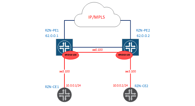
Since in this case the configuration of the bridge domain on both PEs is identical, I will only draw conclusions from the first boxes. First, let’s check that now we don’t have a connection between RZN-CE1 and RZN-CE2 in vlan 100:
bormoglotx@RZN-CE1> show configuration interfaces ae0.100
vlan-id 100;
family inet {
    address 10.0.0.1/24;
}
bormoglotx@RZN-CE1> ping rapid routing-instance VR1 source 10.0.0.1 10.0.0.2
PING 10.0.0.2 (10.0.0.2): 56 data bytes
.....
--- 10.0.0.2 ping statistics ---
5 packets transmitted, 0 packets received, 100% packet loss
Now let's move on to RZN-PE1 and add the interfaces we need and combine them into a bridge domain:
[edit]
bormoglotx@RZN-PE1# show | compare
[edit interfaces ae0]
+    unit 100 {
+        description "L2 for BRIDGE100";
+        encapsulation vlan-bridge;
+        vlan-id 100;
+    }
[edit interfaces ae3]
+    unit 100 {
+        description "to VR1";
+        encapsulation vlan-bridge;
+        vlan-id 100;
+    }
[edit]
+  bridge-domains {
+      BRIDGE-100 {
+          domain-type bridge;
+          vlan-id 100;
+          interface ae0.100;
+          interface ae3.100;
+      }
+  }
As you remember, on the RZN-PE1, the ae0 interface looks at its brother RZN-PE2, and ae3 looks towards RZN-CE1. A similar config is also used on RZN-PE2. Now check the status of our bridge domain:
bormoglotx@RZN-PE1> show bridge domain BRIDGE-100 detail
Routing instance: default-switch
Bridge domain: BRIDGE-100                     State: Active
Bridge VLAN ID: 100
Interfaces:
    ae0.100
    ae3.100
Total MAC count: 0
Everything as we planned - in our domain there are two interfaces and the 100th number of vlan. So far, not a single MAC address has been studied, since there has not yet been an exchange of traffic between RZN-CE1 / 2.
We will correct this oversight by running a ping between the addresses we need:
bormoglotx@RZN-CE1> ping rapid routing-instance VR1 source 10.0.0.1 10.0.0.2
PING 10.0.0.2 (10.0.0.2): 56 data bytes
!!!!!
--- 10.0.0.2 ping statistics ---
5 packets transmitted, 5 packets received, 0% packet loss
round-trip min/avg/max/stddev = 3.451/6.046/13.350/3.674 ms
Now we can check if the MACs appeared in the forwarding table:
bormoglotx@RZN-PE1> show bridge domain BRIDGE-100 detail | match mac
Total MAC count: 2
bormoglotx@RZN-PE1> show bridge mac-table bridge-domain BRIDGE-100
MAC flags (S -static MAC, D -dynamic MAC, L -locally learned, C -Control MAC
SE -Statistics enabled, NM -Non configured MAC, R -Remote PE MAC)
Routing instance : default-switch
Bridging domain : BRIDGE-100, VLAN : 100
MAC MAC Logical NH RTR
address flags interface Index ID
00:05:86:71:1c:c0 D ae0.100
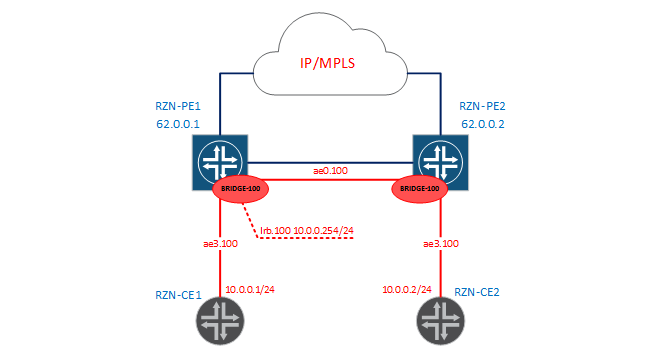
00:05:86:71:e5:c0 D ae3.100 Poppies are studied, connectivity is - all we need - we did. I would like to say a few words that a similar result could be achieved with the help of L2CKT. But firstly, L2CKT is a completely different service that uses MPLS as a transport and does not study MAC addresses (in fact, a pipe from port A to port B), and secondly, you cannot add a third interface to L2CKT (you have to do VPLS), and most importantly, you cannot tie a routing interface (irb) to L2CKT and release hosts from your bridge domain into an external network. For clarity, add the irb interface to our bridge domain, as shown in the diagram:
bormoglotx@RZN-PE1# show | compare
[edit interfaces]
+   irb {
+       unit 100 {
+           description "L3 for BRIDGE-100";
+           family inet {
+               address 10.0.0.254/24;
+           }
+       }
+   }
[edit routing-instances]
+   VIRTUAL-ROUTER {
+       instance-type virtual-router;
+       interface irb.100;
+   }
[edit bridge-domains BRIDGE-100]
+   routing-interface irb.100;
Since inside the labs between the MXs, there is also a 10.0.0.0/24 network, so I moved the irb interface to a virtual router. If our addressing did not overlap, then we could leave this interface in GRT and thereby release the hosts from our L2 domain into the outside world.
Note: the irb interface is not tagged, the unit number is set to 100 for ease of administration. When sending traffic to the routing interface, the tag is removed from the packet, if one is present.
Note: the irb interface will be active only when it is added to the bridge domain with at least one logical interface in the up state.
Note: only one routing interface can be added to one bridge domain.
Now run the ping for example from RZN-CE2 to 10.0.0.254 and check the health of our configuration:
bormoglotx@RZN-CE2> ping routing-instance VR1 rapid source 10.0.0.2 10.0.0.254
PING 10.0.0.254 (10.0.0.254): 56 data bytes
!!!!!
--- 10.0.0.254 ping statistics ---
5 packets transmitted, 5 packets received, 0% packet loss
round-trip min/avg/max/stddev = 3.385/19.526/79.125/29.821 ms
Now let's complicate our task a bit and collect this scheme:
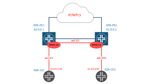
In the new scenario, we need to run L2 between our PEs again, but the problem is that 101 vlan are terminated on RZN-PE1, and 1001 vlan are terminated on RZN-PE2. When I wrote that under certain conditions the bridge domain will be synonymous with the word vlan, then I meant the case presented above (with the 100th vlan). The case under consideration now will prove to you that the bridge domain is not always the same. The first thing you probably thought about is that you need to configure tag rewriting on some of the interfaces, for example, from 1001 to 101 on RZN-PE2. But now I will show you that JunOS will make it much easier for us. Add the following config to RZN-PE1:
[edit]
bormoglotx@RZN-PE1# show | compare
[edit interfaces ae0]
+    unit 101 {
+        encapsulation vlan-bridge;
+        vlan-id 101;
+    }
[edit interfaces ae3]
+    unit 101 {
+        encapsulation vlan-bridge;
+        vlan-id 101;
+    }
[edit bridge-domains]
+   BRIDGE-101 {
+       domain-type bridge;
+       vlan-id 101;
+       interface ae0.101;
+       interface ae3.101;
+   }
As a result, the application of this config will appear on the RZN-PE1 bridge domain BRIDGE-101:
bormoglotx@RZN-PE1> show bridge domain BRIDGE-101
Routing instance        Bridge domain            VLAN ID     Interfaces
default-switch          BRIDGE-101               101
                                                     ae0.101
                                                     ae3.101
Now let's move on to the configuration from the side of RZN-PE2:
[edit]
bormoglotx@RZN-PE2# show | compare
[edit interfaces ae0]
+    unit 101 {
+        encapsulation vlan-bridge;
+        vlan-id 101;
+    }
[edit interfaces ae3]
+    unit 1001 {
+        encapsulation vlan-bridge;
+        vlan-id 1001;
+    }
[edit bridge-domains]
+   BRIDGE-101 {
+       domain-type bridge;
+       vlan-id 101;
+       interface ae3.1001;
+       interface ae0.101;
+   }
There are no tag rewrites in the configuration, if you look at the state of the bridge domain, you can clearly see that the ae3.1001 interface is in the BRIDGE-101 bridge domain:
bormoglotx@RZN-PE2> show bridge domain BRIDGE-101
Routing instance        Bridge domain            VLAN ID     Interfaces
default-switch          BRIDGE-101               101
                                                     ae0.101
                                                     ae3.1001
Good, since we don’t configure the rewriting of the tag, nothing will work. And let's check:
bormoglotx@RZN-CE1> ping rapid routing-instance VR1 source 11.0.0.1 11.0.0.2
PING 11.0.0.2 (11.0.0.2): 56 data bytes
!!!!!
--- 11.0.0.2 ping statistics ---
5 packets transmitted, 5 packets received, 0% packet loss
round-trip min/avg/max/stddev = 5.033/7.733/13.904/3.206 ms
Already interesting - there is connectivity, let's check the forwarding table for the presence of MAC addresses:
bormoglotx@RZN-PE2> show bridge mac-table bridge-domain BRIDGE-101
MAC flags (S -static MAC, D -dynamic MAC, L -locally learned, C -Control MAC
           SE -Statistics enabled, NM -Non configured MAC, R -Remote PE MAC)
Routing instance : default-switch
 Bridging domain : BRIDGE-101, VLAN : 101
   MAC                 MAC      Logical          NH     RTR
   address             flags    interface        Index  ID
   00:05:86:71:1c:c0   D        ae3.1001
   00:05:86:71:e5:c0   D        ae0.101
The MACs in the forwarding table are fine. But why did the connectivity between different vlan appear without configuring tag rewriting? The fact is that this is the default behavior of JunOS. Let's get back to the configuration of the BRIDGE-101 bridge domain itself on RZN-PE2:
bormoglotx@RZN-PE2> show configuration bridge-domains BRIDGE-101
domain-type bridge;
vlan-id 101;
interface ae3.1001;
interface ae0.101;
It’s all about the number indicated by us: vlan-id 101. It works like this: for packets received in this bridge domain with a tag that does not match the 101 tag, JunOS will automatically rewrite the tag. This is easy to see on the interface itself:
bormoglotx@RZN-PE2> show interfaces ae3.1001
  Logical interface ae3.1001 (Index 339) (SNMP ifIndex 580)
    Flags: Up SNMP-Traps 0x20004000
    VLAN-Tag [ 0x8100.1001 ] In(swap .101) Out(swap .1001)
    Encapsulation: VLAN-Bridge
    Statistics        Packets        pps         Bytes          bps
    Bundle:
        Input :             6          0           556            0
        Output:             6          0           570            0
    Adaptive Statistics:
        Adaptive Adjusts:          0
        Adaptive Scans  :          0
        Adaptive Updates:          0
    Protocol bridge, MTU: 1522
I draw your attention to the line with the following contents:
VLAN-Tag [ 0x8100.1001 ] In(swap .101) Out(swap .1001) This line tells us what actions will be performed with the tag on reception from this interface (In (swap .101) - the tag changes to 101) and when transferred to this interface (Out (swap .101) - the tag changes to 1001) . For example, I’ll change the bridge domain config:
[edit]
bormoglotx@RZN-PE2# show bridge-domains BRIDGE-101
domain-type bridge;
vlan-id none;
interface ae3.1001;
interface ae0.101;
And again, let's see what will happen with the tag on ae3.1001:
bormoglotx@RZN-PE2> show interfaces ae3.1001 | match vlan-tag
    VLAN-Tag [ 0x8100.1001 ] In(pop) Out(push 0x0000.1001)
Now the tag is removed (but not rewritten) at the reception, and the tag 1001 is added to the transmission. But since the interface towards RZN-PE1 is also tagged, manipulations with vlan numbers in this case will also be on it (only vlan number 101) :
bormoglotx@RZN-PE2> show interfaces ae0.101 | match vlan-tag
    VLAN-Tag [ 0x8100.101 ] In(pop) Out(push 0x0000.101)
I think that a little bit of bridge domains figured out. Let's now try to create another bridge domain on RZN-PE1 with a vlan tag of 100:
[edit]
bormoglotx@RZN-PE1# show bridge-domains
BRIDGE-100 {
    domain-type bridge;
    vlan-id 100;
    interface ae0.100;
    interface ae3.100;
}
BRIDGE-101 {
    domain-type bridge;
    vlan-id 101;
    interface ae0.101;
    interface ae3.101;
}
VLAN100 {
    vlan-id 100;
}
Check if the commit script will swear at the new configuration:
[edit]
bormoglotx@RZN-PE1# commit check
[edit bridge-domains]
  'VLAN100'
    l2ald: Duplicate vlan-id exists for bridge domain BRIDGE-100
[edit bridge-domains]
  Failed to parse bridge domain hierarchy completely
error: configuration check-out failed
When committing, we get an error - this vlan is already being used in another bridge domain. How to be in such a situation ?? Yes, you can set none and everything will fly, but this is not a solution to the problem, but a crutch (although all the transport is held on crutches and plugs, but still I want a more viable solution). There is a more elegant way - we just create another vlan space, which will be completely isolated from the existing one. This is what a virtual switch will help us with.
Let's take a closer look. We have 4094 vlan on one router. That is, in fact, you are limited in creating bridge domains - a maximum of 4094 domains with a vlan number. JunOS will not allow you to create two domains with the same vlan number. When I showed you the conclusion about the state of the bridge domain, you probably noticed the name routing-instance in this output:
bormoglotx@RZN-PE1> show bridge domain BRIDGE-100 detail
Routing instance: default-switch
Bridge domain: BRIDGE-100                     State: Active
Bridge VLAN ID: 100
Interfaces:
    ae0.100
    ae3.100
Total MAC count: 0
We are interested in this line of the Routing instance: default-switch. That is, even if you did not create any routing-instance with the virtual-switch type, then you will still have one such routing-instance called default-switch. All bridge domains that I configured earlier were added to this instance specifically. When you create a routing-instance with the virtual-switch type, you add one more space from 4094 vlans, which do not overlap and do not affect the already used vlana numbers. That is, by making, for example, two virtual switches, you make it possible within the same router to create three bridge domains with the same vlan number, and all these bridge domains will be completely isolated from each other. In addition, if your topology provides backup paths that can lead to looping, then the virtual switch allows you to run protocols of the stp family, though there is a limitation - you can add only the interface itself, and not its units. And if you have two virtual switches in which you want to add the same interface but different units, then JunOS will return an error when adding an interface to stp. To use stp in this case you will have to use routing-instance layer2-control and the mstp protocol.
But the possibilities of the virtual switch do not end there. In previous versions of creating a bridge domain, we used a direct link between RZN-PE1 and RZN-PE2, like an L2 link and organized connectivity using it. But this does not have a very good effect on fault tolerance, since a break in the specified link will split our stretched L2 domain into two parts. To avoid this, you can use VPLS or EVPN, and we don’t have to do a separate routing-instance with the type vpls or evpn - in the hierarchy of the virtual switch we can configure the VPLS / EVPN port and use it as a trunk port for organizing L2 connectivity with the remote PE . Next, we will configure the virtual switch and will use exclusively VPLS for connectivity between PE routers.
Now we can move on to creating a routing-instance with the type of virtual switch. We will collect three schemes that will differ from each other and show the main features of bridge domains.
1. Bridge domain BRIDGE-2000
2. Bridge domain BRIDGE-2001
3. Bridge domains BRIDGE-302 and BRIDGE-502
In the first scheme, we will use two vlan: 200 and 2000 (on RZN-PE1 we will rewrite the 200 tag for 2000 ), in the second scheme there are also two vlaanas: 201 and 2001 (but here we will use the Service Provider to configure the interface and we won’t rewrite anything - JunOS will do it for us), but in the third scheme we will use three vlana, manually rewrite the tags and configure different bridge domains between RZN-PE1 and RZN-PE2 (one in the virtual switch, the second in the default).
BRIDGE-2000
The service diagram is presented below.
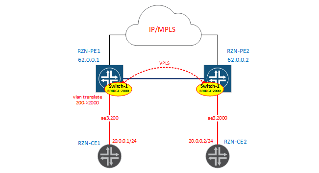
Configure the interface on the RZN-PE1 side:
bormoglotx@RZN-PE1# show interfaces ae3.200
description "to VR2";
encapsulation vlan-bridge;
family bridge {
    interface-mode trunk;
    vlan-id-list 2000;
    vlan-rewrite {
        translate 200 2000;
    }
}
As indicated in the diagram, we rewrite the tag from 200 to 2000. On the RZN-PE2 side, the interface configuration looks simpler:
[edit]
bormoglotx@RZN-PE2# show interfaces ae3.2000
description "to VR2";
encapsulation vlan-bridge;
family bridge {
    interface-mode trunk;
    vlan-id-list 2000;
}
Now let's move on to creating a virtual switch. The configuration will be approximately the same on RZN-PE1 and RZN-PE2, so I’ll give the config only from the first PE:
bormoglotx@RZN-PE1> show configuration routing-instances vSwitch-1
instance-type virtual-switch;
interface ae3.200;
route-distinguisher 62.0.0.1:1;
vrf-target {
    import target:1:1;
    export target:1:1;
}
protocols {
    vpls {
        site-range 2;
        no-tunnel-services;
        site SITE1 {
            site-identifier 1;
        }
    }
}
bridge-domains {
    BRIDGE-2000 {
        vlan-id 2000;
    }
}
Note: in the routing-instance configuration there are RD and RT values. This is not a required attribute of this routing-instance, but I used Kompella's vpls, so I need RD / RT for VPLS to work. If you use, for example, Martini without autodiscovering, then you do not need to specify RT / RD.
Now check the state of the BRIDGE-2000 bridge domain:
bormoglotx@RZN-PE1> show bridge domain instance vSwitch-1 BRIDGE-2000
Routing instance        Bridge domain            VLAN ID     Interfaces
vSwitch-1               BRIDGE-2000              2000
                                                     ae3.200
                                                     lsi.1048832
In addition to the ae3.200 interface being automatically added to the bridge domain, the lsi interface, which is our vpls port, was also added here:
Instance: vSwitch-1
  Local site: SITE1 (1)
    connection-site           Type  St     Time last up          # Up trans
    2                         rmt   Up     Feb 23 12:20:38 2017           1
      Remote PE: 62.0.0.2, Negotiated control-word: No
      Incoming label: 262146, Outgoing label: 262145
      Local interface: lsi.1048832, Status: Up, Encapsulation: VPLS
        Description: Intf - vpls vSwitch-1 local site 1 remote site 2
Now RZN-PE2 in this bridge domain is accessible to us through the VPLS port, and not as it was before through a direct link. Let's check if there is connectivity between our hosts and how things are with the forwarding table:
bormoglotx@RZN-CE1> ping rapid routing-instance VR2 source 20.0.0.1 20.0.0.2
PING 20.0.0.2 (20.0.0.2): 56 data bytes
!!!!!
--- 20.0.0.2 ping statistics ---
5 packets transmitted, 5 packets received, 0% packet loss
round-trip min/avg/max/stddev = 4.571/11.609/37.058/12.731 ms
bormoglotx@RZN-PE1> show bridge mac-table instance vSwitch-1 vlan-id 2000
MAC flags (S -static MAC, D -dynamic MAC, L -locally learned, C -Control MAC
SE -Statistics enabled, NM -Non configured MAC, R -Remote PE MAC)
Routing instance : vSwitch-1
Bridging domain : BRIDGE-2000, VLAN : 2000
MAC MAC Logical NH RTR
address flags interface Index ID
00:05:86:71:1c:c0 D lsi.1048832
00:05:86:71:e5:c0 D ae3.200 Everything is in order - the circuit works. Please note that, as in the default switch, interfaces are not added to the bridge domain itself - JunOS will automatically add them when the configuration is parsed (since we used the Enterprise configuration style). Our business in this scenario is to correctly indicate which interfaces belong to the virtual switch and correctly indicate vlan-id in the bridge domain (well, or vlan-id-range).
BRIDGE-2001
Now let's build the scheme for vlan 201 and 2001.
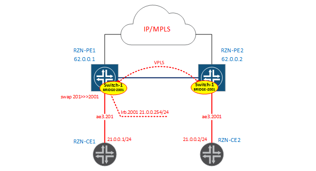
I will not do another virtual switch - just add another bridge domain to vSwitch-1. As I said, we will use the Service Provider style in configuring interfaces without rewriting tags.
Note: inside the virtual switch, as well as inside the bridge domain, nobody forbids you to use interfaces configured using different methods - as you find it easier - just do it, the main thing is not to get confused in the configuration yourself.
Interface configurations look very simple. On RZN-PE1:
[edit]
bormoglotx@RZN-PE1# show interfaces ae3.201
description "to VR2";
encapsulation vlan-bridge;
vlan-id 201;
RZN-PE2 counter-interface:
[edit]
bormoglotx@RZN-PE2# show interfaces ae3.2001
description "to VR2";
encapsulation vlan-bridge;
vlan-id 2001;
Now add the interfaces to our virtual switch:
[edit]
bormoglotx@RZN-PE2# show routing-instances vSwitch-1
instance-type virtual-switch;
interface ae3.2000;
##
## Warning: Only interface with 'interface-mode' is allowed in a virtual-switch
##
interface ae3.2001;
Получили ошибку. Дело в том, что в виртуальный свич в иерархию интерфейсов (сейчас и далее имеется ввиду иерархия [edit routing-instances vSwitch-1 interface]) можно добавить только интерфейсы в режиме транка или акссеса, то есть интерфейс должен быть сконфигурирован в стиле Enterprise. Это еще одно отличие этих двух методов конфигурирования интерфейсов. Если у нас интерфейс сконфигурирован в стиле Enterprise, то мы его не можем указать в иерархии bridge-домена — интерфейс будет добавлять в bridge-домен по номеру влана. Поэтому при конфигурировании виртуального свича нам необходимо добавить в него все наши интерфейсы, которые находятся в режиме транка или аксесса — далее JunOS автоматически добавит их в нужный bridge-домен. А вот интерфейсы, сконфигурированные в стиле Service Provider необходимо указать в bridge-домене вручную. Поэтому, при конфигурировании виртуального свича такие интерфейсы в виртуальный свич в иерархию интерфейсов добавлять не надо — мы их сразу добавляем в нужный нам bridge-домен, после чего интерфейс автоматически будет привязан к виртуальному свичу, в котором находится этот bridge-домен.
[edit]
bormoglotx@RZN-PE2# show routing-instances vSwitch-1
instance-type virtual-switch;
interface ae3.2000;
route-distinguisher 62.0.0.2:1;
vrf-target {
    import target:1:1;
    export target:1:1;
}
protocols {
    vpls {
        site-range 2;
        no-tunnel-services;
        site SITE2 {
            site-identifier 2;
        }
    }
}
bridge-domains {
    BRIDGE-2000 {
        vlan-id 2000;
    }
    BRIDGE-2001 {
        vlan-id 2001;
        interface ae3.2001;
    }
}
Note: VPLS or EVPN port is a trunk port and will skip all vlan and will be added to all bridge domains automatically.
The configuration on RZN-PE1 is similar to RZN-PE2 (only another interface is added to the bridge domain), so I won’t show it. Check the state of the bridge domains on both REs:
bormoglotx@RZN-PE1> show bridge domain instance vSwitch-1 BRIDGE-2001 detail
Routing instance: vSwitch-1
Bridge domain: BRIDGE-2001                    State: Active
Bridge VLAN ID: 2001
Interfaces:
    ae3.201
    lsi.1048832
Total MAC count: 0
bormoglotx@RZN-PE2> show bridge domain instance vSwitch-1 BRIDGE-2001 detail
Routing instance: vSwitch-1
Bridge domain: BRIDGE-2001 State: Active
Bridge VLAN ID: 2001
Interfaces:
ae3.2001
lsi.1048832
Total MAC count: 0Check that on ae3.201 there is a rewriting of tags:
bormoglotx@RZN-PE1> show interfaces ae3.201 | match vlan-tag
    VLAN-Tag [ 0x8100.201 ] In(swap .2001) Out(swap .201)
And to check, run the ping between our hosts and check the forwarding table:
bormoglotx@RZN-CE1> ping rapid routing-instance VR2 source 21.0.0.1 21.0.0.2
PING 21.0.0.2 (21.0.0.2): 56 data bytes
!!!!!
--- 21.0.0.2 ping statistics ---
5 packets transmitted, 5 packets received, 0% packet loss
round-trip min/avg/max/stddev = 7.026/9.563/15.398/3.000 ms
bormoglotx@RZN-PE1> show bridge mac-table instance vSwitch-1 vlan-id 2001
MAC flags (S -static MAC, D -dynamic MAC, L -locally learned, C -Control MAC
SE -Statistics enabled, NM -Non configured MAC, R -Remote PE MAC)
Routing instance : vSwitch-1
Bridging domain : BRIDGE-2001, VLAN : 2001
MAC MAC Logical NH RTR
address flags interface Index ID
00:05:86:71:1c:c0 D lsi.1048832
00:05:86:71:e5:c0 D ae3.201 Well, for the sake of completeness, we will add a routing interface to our virtual switch:
[edit]
bormoglotx@RZN-PE1# show | compare
[edit interfaces irb]
+    unit 2001 {
+        description "L3 for BRIDGE-2001 | vSwitch-1";
+        family inet {
+            address 21.0.0.254/24;
+        }
+    }
[edit routing-instances vSwitch-1 bridge-domains BRIDGE-2001]
+     routing-interface irb.2001;
Note: the routing interface is added immediately to the bridge-domain of the virtual switch we need, this interface does not need to be added to the hierarchy of the virtual switch interfaces.
Now check the availability of the irb interface with RZN-CE2:
bormoglotx@RZN-CE2> ping routing-instance VR2 rapid source 21.0.0.2 21.0.0.254
PING 21.0.0.254 (21.0.0.254): 56 data bytes
!!!!!
--- 21.0.0.254 ping statistics ---
5 packets transmitted, 5 packets received, 0% packet loss
round-trip min/avg/max/stddev = 3.369/10.704/36.307/12.813 ms
There is connectivity, but the MAC address of the irb interface, which is logically visible through the VPLS port, appeared in the forwarding table on RZN-PE2:
bormoglotx@RZN-PE2> show bridge mac-table instance vSwitch-1
MAC flags (S -static MAC, D -dynamic MAC, L -locally learned, C -Control MAC
           SE -Statistics enabled, NM -Non configured MAC, R -Remote PE MAC)
Routing instance : vSwitch-1
 Bridging domain : BRIDGE-2001, VLAN : 2001
   MAC                 MAC      Logical          NH     RTR
   address             flags    interface        Index  ID
   00:05:86:71:17:c0   D        ae3.2001
   00:05:86:71:26:c0   D        lsi.1048576
   00:05:86:71:8d:f0   D        lsi.1048576
For reference, I will give the MAC address of the irb interface with RZN-PE1:
bormoglotx@RZN-PE1> show interfaces irb | match current
  Current address: 00:05:86:71:8d:f0, Hardware address: 00:05:86:71:8d:f0
BRIDGE-302 >>> BRIDGE-502
And
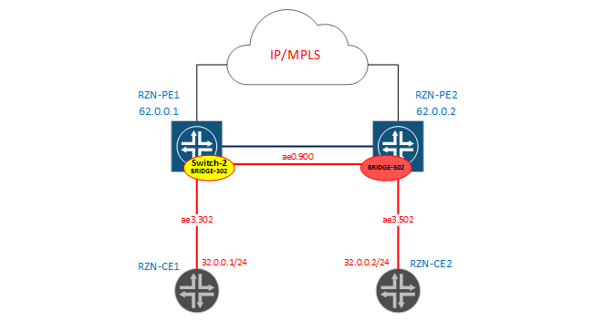
finally we will assemble a scheme in which we will rewrite the tags manually: From the side of RZN-PE1 we have the DOMAIN-302 bridge domain, which is located in the virtual switch vSwitch-2:
[edit]
bormoglotx@RZN-PE1# show | compare
[edit interfaces ae0]
+    unit 900 {
+        encapsulation vlan-bridge;
+        vlan-id 900;
+        input-vlan-map pop;
+        output-vlan-map push;
+    }
[edit interfaces ae3]
+    unit 302 {
+        encapsulation vlan-bridge;
+        vlan-id 302;
+        input-vlan-map pop;
+        output-vlan-map push;
+    }
[edit routing-instances]
+   vSwitch-2 {
+       instance-type virtual-switch;
+       bridge-domains {
+           DOMAIN-302 {
+               interface ae3.302;
+               interface ae0.900;
+           }
+       }
+   }
It can be seen from the configuration that the tag will be removed at the reception, and, logically, the transfer - hanging the tag - is nothing complicated.
From the side of RZN-PE2, we will just have a BRIDGE-502 bridge domain without creating a virtual switch (that is, it will be in the default switch):
bormoglotx@RZN-PE2# show | compare
[edit interfaces ae0]
+    unit 900 {
+        encapsulation vlan-bridge;
+        vlan-id 900;
+        input-vlan-map pop;
+        output-vlan-map push;
+    }
[edit interfaces ae3]
+    unit 502 {
+        encapsulation vlan-bridge;
+        vlan-id 502;
+        input-vlan-map pop;
+        output-vlan-map push;
+    }
[edit bridge-domains]
+   BRIDGE-502 {
+       domain-type bridge;
+       interface ae3.502;
+       interface ae0.900;
+   }
Naturally, here too we shoot at reception, and hang tags when transmitting.
Ultimately, our bridge domains on PE1 / 2 have this state:
bormoglotx@RZN-PE1> show bridge domain instance vSwitch-2
Routing instance        Bridge domain            VLAN ID     Interfaces
vSwitch-2               DOMAIN-302               NA
                                                     ae0.900
                                                     ae3.302
bormoglotx@RZN-PE2> show bridge domain BRIDGE-502
Routing instance Bridge domain VLAN ID Interfaces
default-switch BRIDGE-502 NA
ae0.900
ae3.502Instead of vlan-id, we have NA - since vlan-id is not defined by me, since I manually tag tags on interfaces and cannot set this value. For example, information about the manipulation of vlan tags with RZN-PE1:
bormoglotx@RZN-PE1> show interfaces ae3.302 | match vlan-tag
    VLAN-Tag [ 0x8100.302 ] In(pop) Out(push 0x0000.302)
bormoglotx@RZN-PE1> show interfaces ae0.900 | match vlan-tag
VLAN-Tag [ 0x8100.900 ] In(pop) Out(push 0x0000.900)Now run the ping between the hosts and check if we have connectivity:
bormoglotx@RZN-CE1> ping routing-instance VR3 source 32.0.0.1 32.0.0.2 rapid
PING 32.0.0.2 (32.0.0.2): 56 data bytes
!!!!!
--- 32.0.0.2 ping statistics ---
5 packets transmitted, 5 packets received, 0% packet loss
round-trip min/avg/max/stddev = 5.982/6.443/7.162/0.432 ms
MAC addresses appeared in the forwarding tables:
bormoglotx@RZN-PE1> show bridge mac-table instance vSwitch-2
MAC flags (S -static MAC, D -dynamic MAC, L -locally learned, C -Control MAC
           SE -Statistics enabled, NM -Non configured MAC, R -Remote PE MAC)
Routing instance : vSwitch-2
 Bridging domain : DOMAIN-302, VLAN : NA
   MAC                 MAC      Logical          NH     RTR
   address             flags    interface        Index  ID
   00:05:86:71:56:c0   D        ae3.302
   00:05:86:71:ed:c0   D        ae0.900
True, there is a very important limitation in such a bridge domain (without specifying vlan-id) - you cannot add a routing interface to this bridge domain. When you try to do this, you get an error:
[edit]
bormoglotx@RZN-PE1# commit
[edit routing-instances vSwitch-2 bridge-domains DOMAIN-302 routing-interface]
  'routing-interface irb.302'
    routing-interface can be configured only under bridge-domain with 'vlan-id' or 'vlan-tags'
error: commit failed: (statements constraint check failed)
This can be a very big problem if the L2 domain expands and you suddenly need to release it to the outside world - you will have to rewrite too much config in this case. Therefore, it is not recommended to use the latest model, but I collected it only to demonstrate the possibility of a bridge domain in JunOS.
That's all that I wanted to tell. I tried to explain everything as simple as possible, I hope that the reader understands everything. If there are any additions / comments - write correct / add. Thanks for attention!
PS> In the article I did not touch on some important topics, such as several learning domains in one bridge domain (for an unprepared person it will be a brain explosion), specifying a range of vlans for the bridge domain, etc. These topics are well described in the book Juniper MX-Series-Trio (a book in English) - if you are interested in this topic - then this book will be an excellent tutorial.