Consolidated building information model: a practical lesson on OpenBIM technology
In the summer of 2016, a wonderful article was published demonstrating OpenBIM technology (open interaction of information models) using the example of a multi-apartment residential building project in Yaroslavl, the architectural part of which was designed in the ARCHICAD software product (one of the most powerful BIM solutions for architects), and the design part (KZ section ) - in Tekla Structures (a powerful BIM solution for structural engineers). The article demonstrated the practical possibility of combining several independent solutions among themselves in the framework of joint work on a fairly large object.
Nanosoft experts requested the authors of the article working documentation on the engineering part of the project (performed using classical 2D technology) and reproduced it using modern information modeling technology in the new nanoCAD Engineering BIM software package , which was released in September 2016. And then they supplemented the previously created architectural design model with engineering sections. The result was a consolidated BIM model that combines seven design sections: architecture, structures in terms of reinforced concrete structures and engineering networks in parts of electrics / lighting, low currents, security systems, heating, water supply and sewage.
This, in my opinion, is a certain achievement for the Russian market - personally, I have not seen much of BIM projects combining more than three sections into one model. And here is a composite information model that combines seven sections created in software products from independent developers, one of which is Russian! Therefore, in this practical and technical article, we decided to share data with you, with which you can independently assemble a composite BIM model, in practice, feel the essence of information models, understand the details and, having found out all the advantages for yourself, apply this knowledge in practice. And in the comments to the article we suggest discussing near-thematic issues.
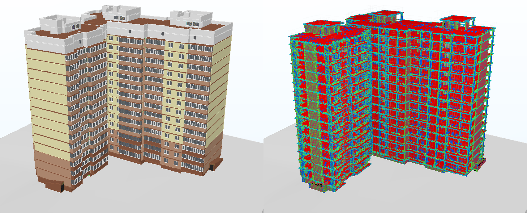
Fig. 1. Information (BIM) models of a residential building: architectural and design part
The author of the project and architectural model created in the ARCHICAD program is architect A. Lysokon. All load-bearing structures were completed in the Tekla Structures program by designers V. Sizov and D. Roik. The chief engineer of the project is A. Medvedev.
The engineering part (Fig. 2) using BIM technology (Building Information Modeling - information modeling of buildings / structures) was recreated according to 2D documentation by Nanosoft specialists: the electrical part - D. Schurov, heating, water supply and sewage - N. Suvorov, low currents and security systems - M. Badayev, consolidated model and overall coordination - D. Ozhigin.

Fig. 2. An informational (BIM) model of a residential building recreated according to 2D documentation regarding engineering: electrics, lighting, low currents, security systems, heating, water supply and sewage
firstly, the building actually consists of two buildings (Fig. 3) - independent parts, offset from each other by a height of 800 mm. This was unexpected, and we wondered a little how to organize the project: either two separate buildings, or one model for the building. In the end, they decided to make a single model (within each section) - in the future, this solution paid off, since we were able to carry out engineering calculations throughout the building;
secondly, the beginning of the architectural project does not coincide with the origin of the axis grid: the intersection of the A1 axes lies at the coordinates x = 19454.1, y = -271.4, z = 0. Nevertheless, we placed the origin of the coordinates of the engineering project at point A1, and when the collection of composite models took into account this bias;
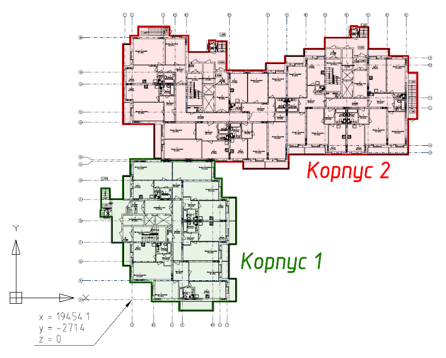
Fig. 3. The project consists of two buildings, and the intersection of the A1 axes is located at coordinates x = 19454.1, y = -271.4, z = 0
third, we had the following initial data from the architect:
We also had a single design model in IFC format, which we practically did not use, since we did not change the project. But we loaded the design model into a composite one and saw some conflicts. For example, between an engineer and reinforcing rods.
Of all the software products used, at any time, you can unload the information model in IFC format, and it will contain the latest and most current information. For practical work, we formed, using nanoCAD Electro, SCS, OPS, VK and Heating software products, separate IFC models, which we collected in a rar archive .
Please note that the archive also contains the file MKZHD.AS.ifc- This is the architectural part of the project (IFC-model, formed from ARCHICAD). Here are * .dwg files that are obtained from the ARCHICAD BIM model in an automated mode and are updated as the main model is updated - this is a two-dimensional drawing-job of the first floor and a three-dimensional model of the first floor (building 1 and building 2). In fact, this is the initial data on the ground floor for engineering design. We will use them to illustrate the collection of the composite model.
But as an experiment, you can use other IFC-viewers:
Install software products and launch nanoCAD Plus 8.1.
Next, insert the two-dimensional substrate. To do this, use the ATTACH command (the Insert / External link ... menu ) to connect the file 01 Ground floor 2D.dwg from the downloaded materials (Fig. 4). I draw your attention to the fact that when I insert, I use the relative path for the substrate (the section Defining the path in the Insert external link dialog ) and specify the coordinates of the insert: x = -19454.1, y = 271.4, z = 0 (that is, I place the origin at the intersection point of the A1 axes )
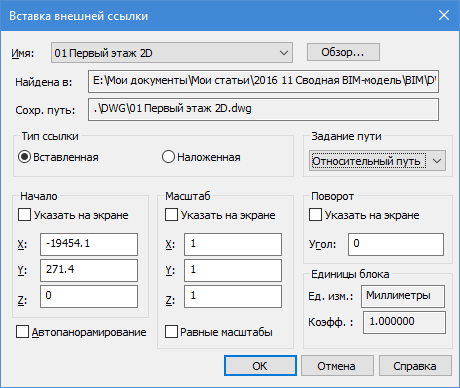
Fig. 4. When placing the substrates, we specify the coordinates of the insertion point and use the relative insertion paths.
When the substrate appears on the document field, move the cursor to the center of the screen and hold down the SHIFT key + mouse wheel and rotate the drawing at an angle into 3D space. Or expand it into standard SE isometry (_SEISO command).
Repeat the insert backing command for the files 01 Ground floor 3D (part 01) .dwg and 01 Ground floor 3D (part 02) .dwgwith the same insertion coordinates as for a two-dimensional project, three-dimensional geometry of the ground floor architecture will be added to your project. This is not a BIM model yet, since the resulting geometry does not contain any information about the elements. * .dwg files give only geometry, and we will use it in order to understand the difference with the real BIM model.
And finally, set the way to display three-dimensional space: in the View / Visual Styles menu, select either Fast with edges or Fast .
If everything is done correctly, then you will get the result shown in Fig. 5.

Fig. 5. We place a two-dimensional and three-dimensional substrate in the nanoCAD project in order to visually see the process of collecting a BIM project
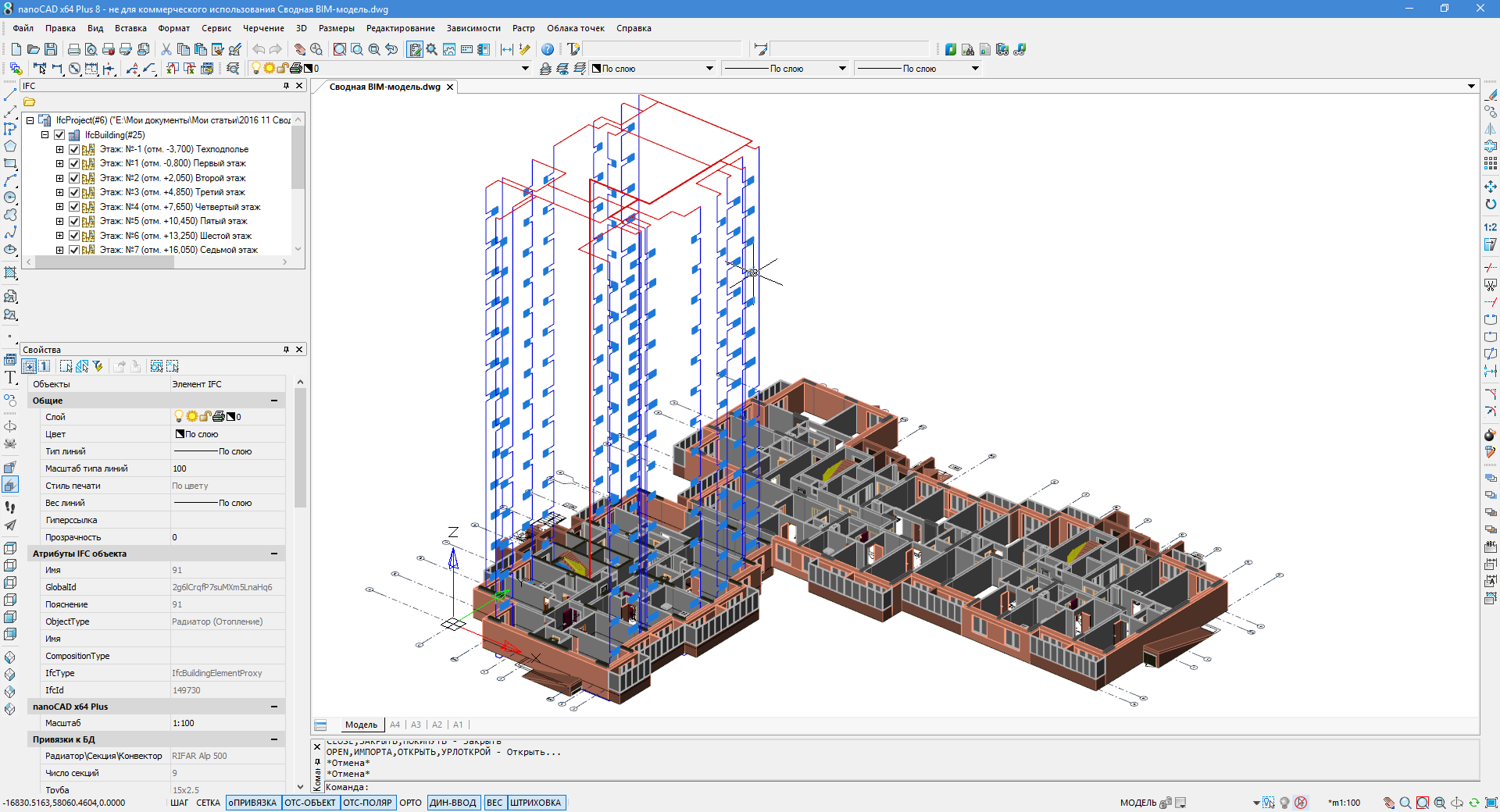
Fig. 6. Three-dimensional model of the project with * .dwg- and IFC data
Also note that the BIM model contains information on the objects: for example, if you select a radiator, then the information on the object is displayed in the properties window - volume, heat load, installation height relative to the floor, power, name, link to the manufacturer’s website, etc. . All this information was embedded in the nanoCAD Heating software product and accurately transferred to the nanoCAD Plus environment thanks to the IFC format, which is precisely designed for transferring such information between programs. Compare, for example, with the properties of objects from a * .dwg file, which contain only general information such as color, layer, line thickness (see figure 7).

Fig. 7. IFC objects contain much more parameters compared to DWG blocks
Information from IFC-objects can be used both in the Selection panel when setting up samples for a project and in autoformable specifications (for example, in equipment specifications) - see fig. 8.
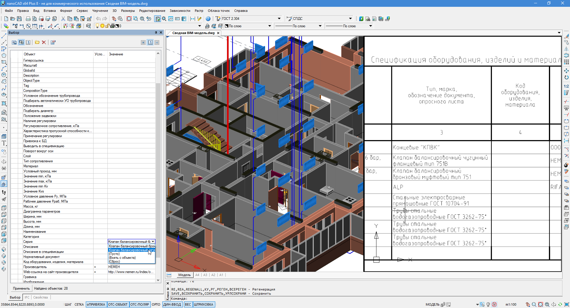
Fig. 8. Parameters and information from IFC objects can be used in tables and samples
For each section, a list of objects is created in the IFC panel. Each added section contains IFC-objects with their specific data (embedded in the corresponding software products), which can either be set manually, or taken from a database, or calculated as a result of calculations.
At the same time, each section added significantly loads the computer, and in order to assemble a complete model, powerful resources are needed. The most difficult model in this project is the water supply model - most likely, its loading will have to wait a while. Therefore, in real work, you can not combine the entire model, but only certain sections or even floors - this will allow solving practical problems without significantly increasing computer resources.
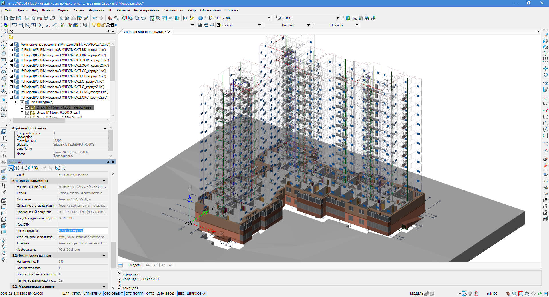
Fig. 9. Consolidated BIM-model allows specialists to work in a single information space
nanoCAD Plus as a viewer provides model display, navigation both in parallel (SHIFT + mouse wheel) and perspective projection (3D FLIGHT command and WSAD keys for control). This allows you to climb inside the project and visually find problem areas, conflicts and shortcomings. In addition, using automatic specifications, you can quickly select the desired IFC-objects and control the parameters of engineering networks. In general, this makes it possible to present the project as a whole, taking into account the situation in related sections, distribute further work between specialists and conduct work in a single information space (Fig. 10 and 11).
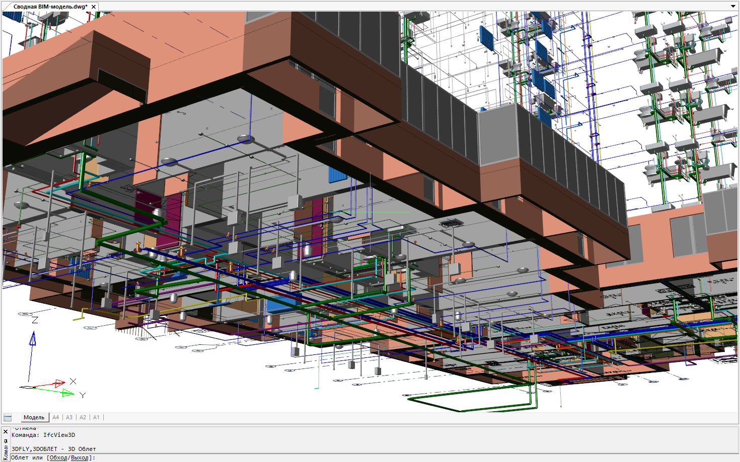
Fig. 10. The nanoCAD Plus platform's navigation features allow you to view a consolidated BIM model from any angle
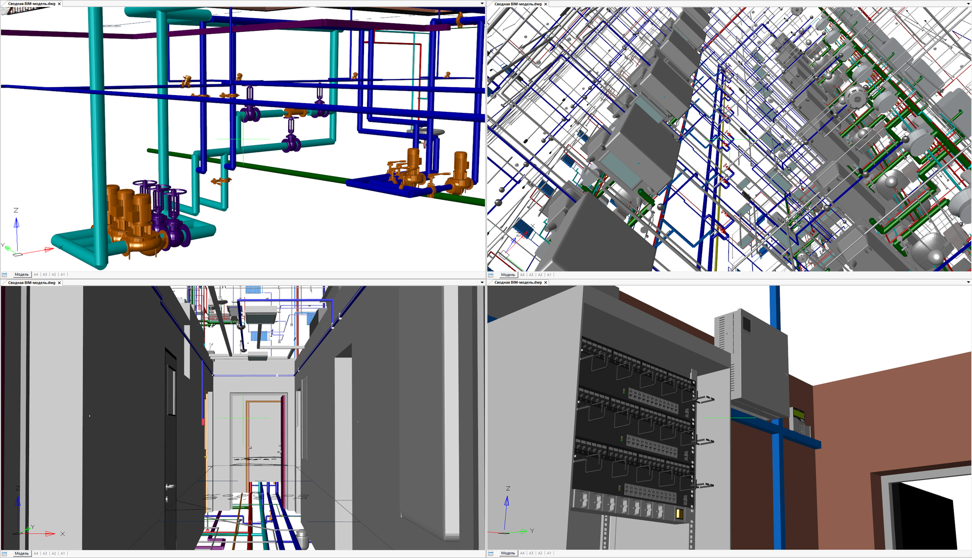
Fig. 11. Different types of consolidated BIM models in the nanoCAD Plus 8.1 working window
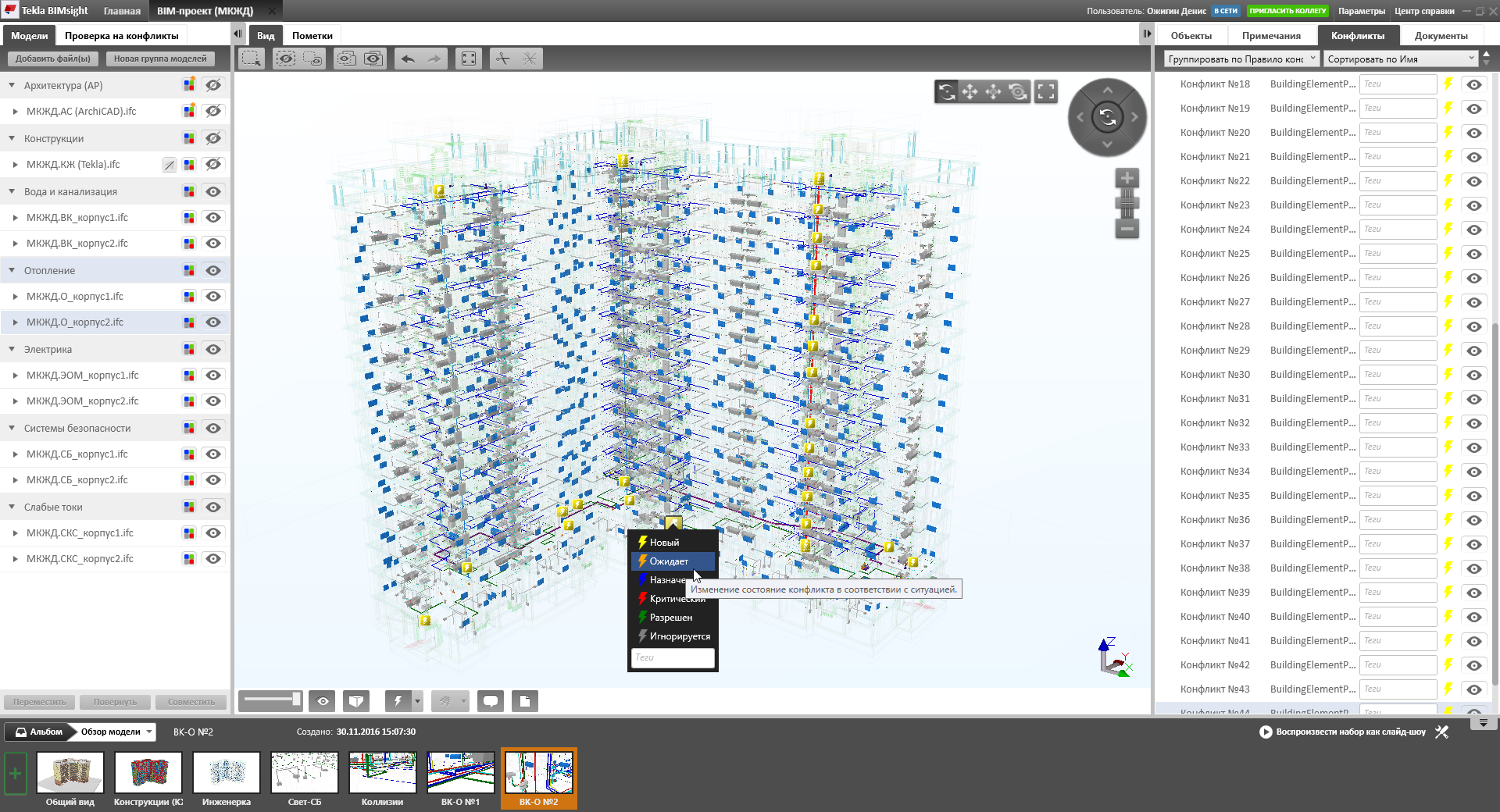
Fig. 12. The consolidated BIM model in the IFC-viewer Tekla BIMsight allows you to automatically find collisions between systems.
However, further development is still required. It is necessary to develop the speed of working with IFC data, improve update tools within the framework of consolidated BIM models, improve the integration between solutions at the level of information transfer, standardize the parameters, classes and hierarchy of building structures and materials in order to automate calculations, transfer changes between projects and sections . All this is the work of the near future.
Nanosoft experts invite you to cooperate and are ready to advise you on the creation of BIM-models of engineering networks and the organization of BIM-interaction.
Denis Ozhigin,
Technical Director Nanosoft
Nanosoft experts requested the authors of the article working documentation on the engineering part of the project (performed using classical 2D technology) and reproduced it using modern information modeling technology in the new nanoCAD Engineering BIM software package , which was released in September 2016. And then they supplemented the previously created architectural design model with engineering sections. The result was a consolidated BIM model that combines seven design sections: architecture, structures in terms of reinforced concrete structures and engineering networks in parts of electrics / lighting, low currents, security systems, heating, water supply and sewage.
This, in my opinion, is a certain achievement for the Russian market - personally, I have not seen much of BIM projects combining more than three sections into one model. And here is a composite information model that combines seven sections created in software products from independent developers, one of which is Russian! Therefore, in this practical and technical article, we decided to share data with you, with which you can independently assemble a composite BIM model, in practice, feel the essence of information models, understand the details and, having found out all the advantages for yourself, apply this knowledge in practice. And in the comments to the article we suggest discussing near-thematic issues.
Introduction
Let me remind you that the project itself (Fig. 1) was provided by the investment company ProfStroy LLC, whose activities are aimed at the construction of affordable and comfortable housing, mainly economy class, in Yaroslavl and the Yaroslavl municipal district.Fig. 1. Information (BIM) models of a residential building: architectural and design part
The author of the project and architectural model created in the ARCHICAD program is architect A. Lysokon. All load-bearing structures were completed in the Tekla Structures program by designers V. Sizov and D. Roik. The chief engineer of the project is A. Medvedev.
The engineering part (Fig. 2) using BIM technology (Building Information Modeling - information modeling of buildings / structures) was recreated according to 2D documentation by Nanosoft specialists: the electrical part - D. Schurov, heating, water supply and sewage - N. Suvorov, low currents and security systems - M. Badayev, consolidated model and overall coordination - D. Ozhigin.
Fig. 2. An informational (BIM) model of a residential building recreated according to 2D documentation regarding engineering: electrics, lighting, low currents, security systems, heating, water supply and sewage
Initial data: we understand the structure of the building
Having received materials on the building, we found out the following:firstly, the building actually consists of two buildings (Fig. 3) - independent parts, offset from each other by a height of 800 mm. This was unexpected, and we wondered a little how to organize the project: either two separate buildings, or one model for the building. In the end, they decided to make a single model (within each section) - in the future, this solution paid off, since we were able to carry out engineering calculations throughout the building;
secondly, the beginning of the architectural project does not coincide with the origin of the axis grid: the intersection of the A1 axes lies at the coordinates x = 19454.1, y = -271.4, z = 0. Nevertheless, we placed the origin of the coordinates of the engineering project at point A1, and when the collection of composite models took into account this bias;
Fig. 3. The project consists of two buildings, and the intersection of the A1 axes is located at coordinates x = 19454.1, y = -271.4, z = 0
third, we had the following initial data from the architect:
- floor plans in * .dwg format, downloaded from the ARCHICAD project - we used these materials as a basis (substrate) for engineering design and preparation of working documentation for the section,
- a single architectural model in IFC format - we used this model as a substrate to coordinate the three-dimensional equipment layout and get a general idea of the model,
- working documentation in * .dwg format - since we reproduced the project (rather than designed from scratch), we used these materials to understand the engineering solution.
We also had a single design model in IFC format, which we practically did not use, since we did not change the project. But we loaded the design model into a composite one and saw some conflicts. For example, between an engineer and reinforcing rods.
Output for practical assignment (IFC-models)
We get working documentation, calculations, project specifications within the framework of software products: in particular, engineering sections - from nanoCAD Engineering BIM . How exactly? This is slightly beyond the scope of our article, so come to our seminars and webinars for more information. Or look, for example, the playlist “Information Modeling Technology (BIM) and nanoCAD CAD platform” on our YouTube channel ( https://www.youtube.com/playlist?list=PLaWJ5dzYEDosgGNi7SH3xtxZWaqDc4y4_ ). In the framework of this practical task, we will assemble only a consolidated BIM model.Of all the software products used, at any time, you can unload the information model in IFC format, and it will contain the latest and most current information. For practical work, we formed, using nanoCAD Electro, SCS, OPS, VK and Heating software products, separate IFC models, which we collected in a rar archive .
Please note that the archive also contains the file MKZHD.AS.ifc- This is the architectural part of the project (IFC-model, formed from ARCHICAD). Here are * .dwg files that are obtained from the ARCHICAD BIM model in an automated mode and are updated as the main model is updated - this is a two-dimensional drawing-job of the first floor and a three-dimensional model of the first floor (building 1 and building 2). In fact, this is the initial data on the ground floor for engineering design. We will use them to illustrate the collection of the composite model.
Software
For practical work, we need one program - the nanoCAD Plus 8.1 platform, which can be downloaded on the developer's website: www.nanocad.ru/products/detail.php?ID=606057 .But as an experiment, you can use other IFC-viewers:
Install software products and launch nanoCAD Plus 8.1.
Step 1: forming the substrate
This step is more preparatory and necessary so that you clearly understand what is happening. Create a new project in nanoCAD Plus (the NEW team) and save it under the name BIM Consolidated Model.dwg .Next, insert the two-dimensional substrate. To do this, use the ATTACH command (the Insert / External link ... menu ) to connect the file 01 Ground floor 2D.dwg from the downloaded materials (Fig. 4). I draw your attention to the fact that when I insert, I use the relative path for the substrate (the section Defining the path in the Insert external link dialog ) and specify the coordinates of the insert: x = -19454.1, y = 271.4, z = 0 (that is, I place the origin at the intersection point of the A1 axes )
Fig. 4. When placing the substrates, we specify the coordinates of the insertion point and use the relative insertion paths.
When the substrate appears on the document field, move the cursor to the center of the screen and hold down the SHIFT key + mouse wheel and rotate the drawing at an angle into 3D space. Or expand it into standard SE isometry (_SEISO command).
Repeat the insert backing command for the files 01 Ground floor 3D (part 01) .dwg and 01 Ground floor 3D (part 02) .dwgwith the same insertion coordinates as for a two-dimensional project, three-dimensional geometry of the ground floor architecture will be added to your project. This is not a BIM model yet, since the resulting geometry does not contain any information about the elements. * .dwg files give only geometry, and we will use it in order to understand the difference with the real BIM model.
And finally, set the way to display three-dimensional space: in the View / Visual Styles menu, select either Fast with edges or Fast .
If everything is done correctly, then you will get the result shown in Fig. 5.
Fig. 5. We place a two-dimensional and three-dimensional substrate in the nanoCAD project in order to visually see the process of collecting a BIM project
Tip 1: use the SHIFT key and the mouse wheel simultaneously pressed to rotate the model - this will allow you to view the project from all sides.
Tip 2: if you have a powerful computer, but when you rotate the model “blinks”, disabling face painting, then in the program settings ( Tools / Settings ) you can turn off Triangle Rendering Optimization ( Graphic subsystem / Rendering optimization ) - after that nanoCAD will render the model completely even when spinning. Much more comfortable for the eyes.
Step 2: add the BIM model
We are fully prepared to assemble a consolidated BIM model. Now, using the IFCVIEW3D command, upload the file MKZHD.O_korpus1.ifc . You can choose any other file, but I recommend starting with this one - it is small in size, loads quickly and is pretty visual. If everything is done correctly, then you will have a heating system of the building in building 1 - see fig. 6.Tip 3: if you don’t see a model after loading the IFC file, save the file to your hard drive.Please note that the structure of the loaded IFC file has appeared on the IFC functional panel (the panel is located next to the Properties panel and is turned on / off via the View / Panels / Functional panels / IFC ... menu ): floors, element classes, heights, etc. . The panel allows you to quickly find items by their classes, as well as instantly turn off the visibility of objects - you can, for example, turn off objects on the upper floors.
Fig. 6. Three-dimensional model of the project with * .dwg- and IFC data
Also note that the BIM model contains information on the objects: for example, if you select a radiator, then the information on the object is displayed in the properties window - volume, heat load, installation height relative to the floor, power, name, link to the manufacturer’s website, etc. . All this information was embedded in the nanoCAD Heating software product and accurately transferred to the nanoCAD Plus environment thanks to the IFC format, which is precisely designed for transferring such information between programs. Compare, for example, with the properties of objects from a * .dwg file, which contain only general information such as color, layer, line thickness (see figure 7).
Fig. 7. IFC objects contain much more parameters compared to DWG blocks
Information from IFC-objects can be used both in the Selection panel when setting up samples for a project and in autoformable specifications (for example, in equipment specifications) - see fig. 8.
Fig. 8. Parameters and information from IFC objects can be used in tables and samples
Step 3: form a consolidated BIM model
Repeating step 2 sequentially for other IFC models, we can assemble a composite BIM model (Fig. 9).For each section, a list of objects is created in the IFC panel. Each added section contains IFC-objects with their specific data (embedded in the corresponding software products), which can either be set manually, or taken from a database, or calculated as a result of calculations.
At the same time, each section added significantly loads the computer, and in order to assemble a complete model, powerful resources are needed. The most difficult model in this project is the water supply model - most likely, its loading will have to wait a while. Therefore, in real work, you can not combine the entire model, but only certain sections or even floors - this will allow solving practical problems without significantly increasing computer resources.
Fig. 9. Consolidated BIM-model allows specialists to work in a single information space
nanoCAD Plus as a viewer provides model display, navigation both in parallel (SHIFT + mouse wheel) and perspective projection (3D FLIGHT command and WSAD keys for control). This allows you to climb inside the project and visually find problem areas, conflicts and shortcomings. In addition, using automatic specifications, you can quickly select the desired IFC-objects and control the parameters of engineering networks. In general, this makes it possible to present the project as a whole, taking into account the situation in related sections, distribute further work between specialists and conduct work in a single information space (Fig. 10 and 11).
Fig. 10. The nanoCAD Plus platform's navigation features allow you to view a consolidated BIM model from any angle
Fig. 11. Different types of consolidated BIM models in the nanoCAD Plus 8.1 working window
Step 5: updating IFC models
Currently, nanoCAD Plus 8.1 updates models by removing the IFC model from the IFC panel and reloading the new version of the model. Here we need to optimize the process - in the future we want to implement the loading of IFC data as a substrate. Then they will be updated independently after changing the IFC file.Step 6: consolidated BIM models in other solutions
As an additional task, you can try to assemble composite models in Tekla BIMsight (free solution) (Fig. 12) and in Solibri Model Checker (paid solution; the free version of Solibri Model Viewer allows you to open only one IFC model). These products are developed as universal solutions for viewing IFC and are expanded by functionality for automatic collision search, reporting on changes, as well as a wider range of model visualization tools.Fig. 12. The consolidated BIM model in the IFC-viewer Tekla BIMsight allows you to automatically find collisions between systems.
Conclusion
BIM technology is developing, and every day designers have additional tools for creating high-quality projects. It was difficult to assemble a model of a multi-storey residential building with architecture and engineering within a single space a couple of years ago, and now this is a very common practical task.However, further development is still required. It is necessary to develop the speed of working with IFC data, improve update tools within the framework of consolidated BIM models, improve the integration between solutions at the level of information transfer, standardize the parameters, classes and hierarchy of building structures and materials in order to automate calculations, transfer changes between projects and sections . All this is the work of the near future.
Nanosoft experts invite you to cooperate and are ready to advise you on the creation of BIM-models of engineering networks and the organization of BIM-interaction.
Denis Ozhigin,
Technical Director Nanosoft