Overview of CAD on the geometric core C3D
In previous articles on the C3D geometric core, we analyzed its internal structure ( kernel structure , visualization module ) and explained how it differs from the CAD-system API ( article ). The core, as a tool for a CAD developer, can only manifest its qualities in products written on its basis.
Now on our core released more than 20 commercial and corporate CAD. In the review we will tell you what kind of products, what role the core plays in them and what are the features of its use. Many products mentioned in the review have already appeared on Habré. We will give links to articles about them.
The first one we always call COMPAS-3D, from which, in fact, began the history of the nucleus. Today, the system employs more than 520,000 users (including commercial, home, educational licenses). For 12 years, the kernel developed as an internal component of KOMPAS-3D and derived its initial functionality from the requirements of its developers. Three-dimensional modeling was implemented with the C3D Toolkit tools (geometric core, parametric solver, converters), except for visualization - a 3D engine appeared only two years ago. Now KOMPAS-3D continues to influence the core: the most pressing tasks are modeling complex forms and increasing productivity.
In the latest version of the C3D Modeler kernel, we added new special cases for constructing rounding and rounding of three faces. In general, rounding off remains one of the most difficult tasks for geometric kernels, since cover all options for their construction is impossible.
Special cases of construction of rounding
Rounding of three faces (or full rounding)
Some COMPASS-3D applications also work directly with the geometric core. The article presents an example of the application “Shafts and mechanical transmissions of 3D”, where the exact models of the elements of mechanical gears (bevel, hypoid, etc.) are created using the core.
Another well-known CAD system in which the C3D Modeler core is presently present is the nanoCAD. In the article about the new nanoCAD Plus 10 platformdows described how the 3D modeling module works: the connection of the geometric core — C3D or ACIS — takes place at the user's choice, and our kernel is installed by default.
nanoCAD Plus with a 3D modeling module on C3D
In order to translate into C3D, operations that were previously performed on ACIS, it was necessary to overcome more than one barrier. Changing the 3D core entails changing the data of associative links, changing the orientation of faces and edges, changing the type of geometry of edges, changing the topology of the body when building, changing the topology of the body when changing the format of the 3D model, deviating the geometry of complex surfaces. All this, the developers of Nanosoft managed to win.
If mechanical CAD systems have moved to the paradigm of three-dimensional design for a long time, then for CAD electronic devices 3D becomes mainstream only now. World and Russian developers are here in approximately equal positions in terms of the capabilities of their products. And what is nice for us is that both work with our core.
A year ago, Altium, the developer of the worldwide popular Altium Designer (successor to P-CAD), licensed the C3D Toolkit, and in the near future a new version of Altium Designer should be released, in which 3D modeling has already been done with our tools.
In parallel with the Altium, the Russian company Eremex is developing a system for designing printed circuit boards Delta Design, based on the geometric core C3D Modeler.
PCB model in Delta Design
For Delta Design we had to solve the problem of visualization of printed circuit boards with a large number of layers and components - to speed up operations with regions in the core.
Industrial design engineers are well acquainted with NTP Pipeline and its products START, PASSAT, Union-FEM. Since 2014, in the PASSAT program, which performs the strength calculations of vessels and devices, all elements of the 3D model are created on the C3D Modeler core, and this is a fairly large list: cylindrical shells and conical transitions, welded bottoms and detachable covers, reinforcement holes, tie-ins into the shells and convex bottoms, flange connections, etc.
The kernel is also responsible for calculating the geometric characteristics (volume, surface area, center of gravity, moment of inertia), and the C3D Converter converters are responsible for exporting models to the ACIS, IGES, Parasolid, and STEP formats.

PASSAT
This year, NTP Pipeline connected the core to its second product, Fitting-FEM (strength calculations for tie-in units in equipment), but not yet for all geometric operations. Due to the nature of the models, difficulties have arisen with Boolean operations and the projection of curves onto the surface. Basically, in our core, Fitting-FEM stores curves and builds fillets.
Union-FEM
In the development of design software, it uses the C3D core and the RFNC-VNIITF nuclear center of the Rosatom State Corporation. We have no right to tell about the purpose of the product, but you can show some screenshots.
At first, our components were used in this product only for modeling geometry and importing / exporting finished geometry through exchange formats, and developers did visualization on their own components. But a year ago they switched to our C3D Vision engine. According to their assessment, the quality has improved and the output speed of the scene elements has increased. Now we are waiting for tools to create, output and work with 2D-scene.
Despite external differences, in terms of the geometric core, the architecture is not much different from mechanical engineering. Therefore, when the team of Renga Software Rengabim chose which core to write its BIM, our C3D proved to be very worthy.
Now developers use core, solver and converters in three products: Renga Architecture, Renga Structure and Renga MEP. C3D tools are responsible for creating the geometry of architectural and structural objects, transforming geometry, obtaining sections and facades of buildings, editing trails and equipment connected to them, calculating masses and areas, and importing solid-state models.
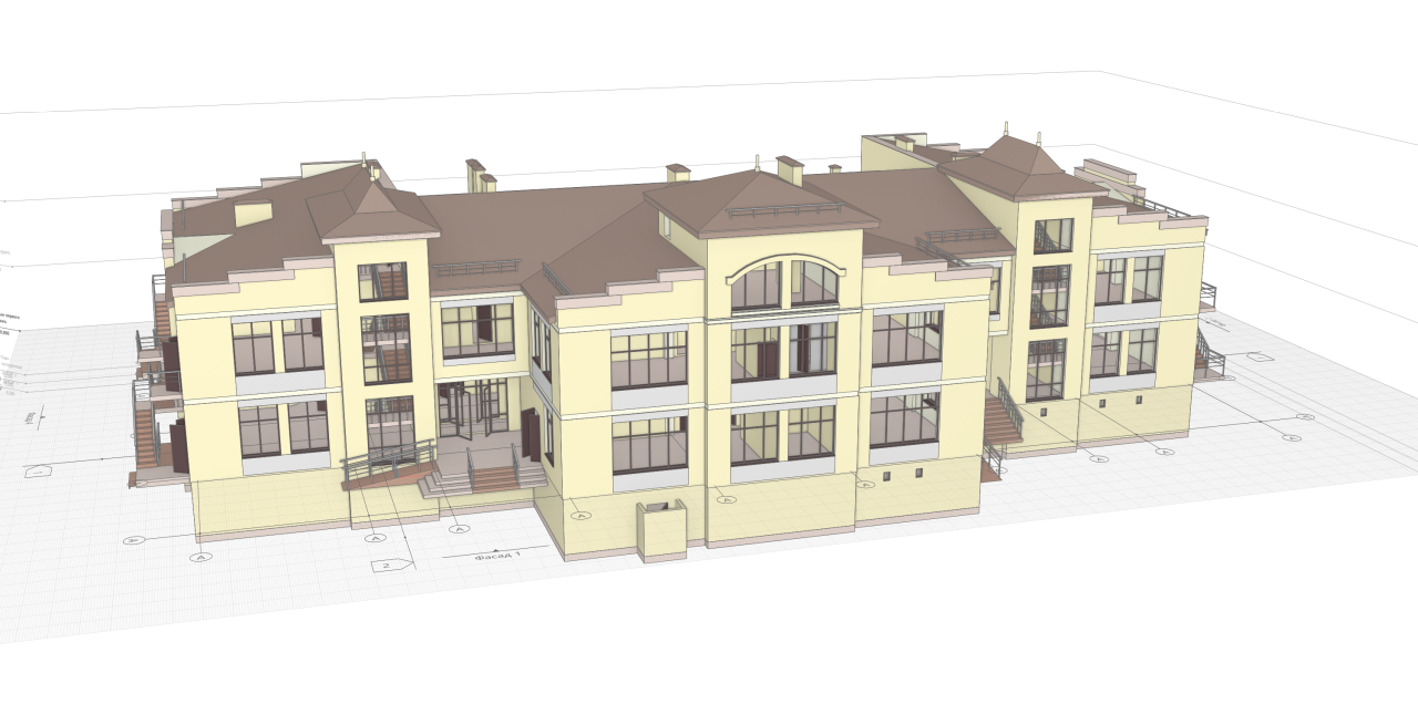
The project of the kindergarten in the city of Gelendzhik in Renga Architecture

Renga Structure
This group includes applications that in Russia are used to be called furniture CAD. BAZIS-Center was the first to start using the C3D core, when we did not have any documentation, no official price for the license, or the very name C3D. He described his experience of choosing and implementing the kernel in detail in x512 in the article “ Nuclear technologies in CAD .
Let us single out in the article one moment related to the specifics of furniture design - modeling of curved facades. At the request of BAZIS Center, we added non-sheeting bodies to C3D Modeler. To bend any body, it is sufficient to specify the cutting plane, the number and thickness of the pieces into which the body will be broken, and for each piece, specify the location of the bend axis and its neutral layer radius. Cylindrical folds will be formed from body pieces, in which a layer spaced at a distance of a neutral radius from the axis will not experience compression or stretching. Now in CAD Basis, you can simulate curved facades with milling.

Bending non-leaf bodies
The program complex K3-Furniture for the design, production and sale of cabinet furniture is developing the Nizhny Novgorod Center GeoS. This is our only customer who uses only the parametric solver C3D Solver, without a geometric core. It is used to program the visualization of the kinematics of various furniture mechanisms, for example, lift elevators.
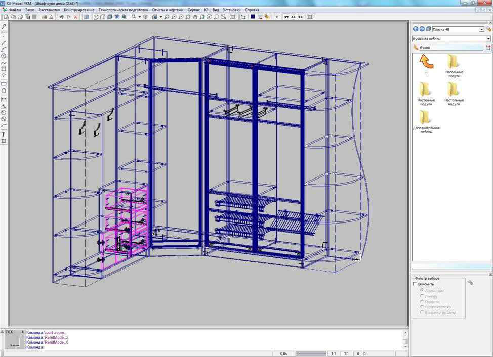
K3-Furniture
Among our customers, there are still few followers of cloud technologies, but if they decide to go on this road, then we also have this experience.
For example, on the C3D Modeler core, KOMPAS is implemented: 24, the Android model viewer KOMPAS-3D ( article ).
Novosibirsk company LEDAS has integrated the core with its cloud platform LEDAS Cloud Platform (LCP). The platform transfers CAD applications to the web environment and provides in the browser the functions of data storage and management, visualization, navigation, communication and collaboration.
At the request of a single American customer, we made a parametric C3D Solver for JavaScript. A product written on its basis can not only function in the browser, but also produce geometric calculations on the client side. As far as we know, not a single developer in the world has a similar solution.
For the convenience of work and information exchange in PDM-systems, a secondary presentation of documents is formed (a copy in a neutral format). For this, VRML, eDrawings, 3D PDF can be used. Developers LOTSMAN: PLM for 15 years tried different options and last year stopped on our viewer C3D Viewer ( article ). It allows you to view 3D models and annotate. By the way, the annotation functionality was developed by order of the LOTSMAN: PLM team and is included in the paid Enterprise version of the product. The basic C3D Viewer remains free (you can download it here ).
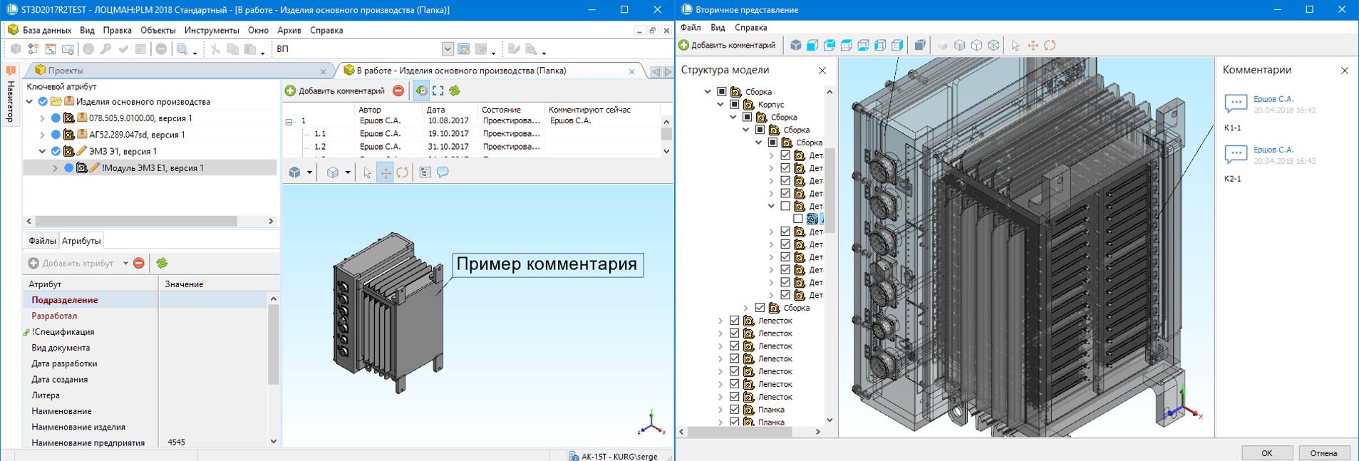
Secondary presentation in LOTSMAN: PLM
Usually, in systems of preparation of control programs for CNC machines, the geometric core plays an important, but not the key role: it works in the preprocessor, ensuring the import of a geometric model from CAD systems and the refinement of geometry before programming processing. In essence, the core is needed to saturate CAM systems with CAD functionality demanded by technologists. Do not do without the 3D-core and developers of integrated CAD / CAM solutions.
At Mordovia State University, a long-standing team on the CAM-direction. First they wrote “CNC module. Turning ”on API KOMPAS, and later -“ CNC module. Milling ”for 2.5 and 3-axis machining directly on the C3D core. Their path is different from the traditional approach of CAM developers to the core.
The application is integrated into the KOMPAS-3D workspace and uses the CAD model created in KOMPAS as a source of geometric information. With the help of C3D functions, spatial areas of material removal, their subtraction from the workpiece, the construction of three-dimensional trajectories are modeled. The specificity of using C3D for CAM tasks is that such complex geometric modeling operations as building shells, finding intersection curves, Boolean operations, are not the ultimate modeling objects (as in CAD systems), but are elementary bricks for implementing high-level algorithms for the CAM area. This imposes additional requirements for the coordination of the accuracy of the results obtained through the kernel, with the overall accuracy of calculations in the framework of high-level tasks.
CNC module. Milling
Interested developers can test the C3D Toolkit themselves. All components are provided free of charge for three months, with documentation, upon request on our website.
Now on our core released more than 20 commercial and corporate CAD. In the review we will tell you what kind of products, what role the core plays in them and what are the features of its use. Many products mentioned in the review have already appeared on Habré. We will give links to articles about them.
CAD / Engineering
The first one we always call COMPAS-3D, from which, in fact, began the history of the nucleus. Today, the system employs more than 520,000 users (including commercial, home, educational licenses). For 12 years, the kernel developed as an internal component of KOMPAS-3D and derived its initial functionality from the requirements of its developers. Three-dimensional modeling was implemented with the C3D Toolkit tools (geometric core, parametric solver, converters), except for visualization - a 3D engine appeared only two years ago. Now KOMPAS-3D continues to influence the core: the most pressing tasks are modeling complex forms and increasing productivity.
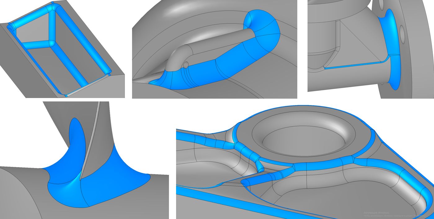
In the latest version of the C3D Modeler kernel, we added new special cases for constructing rounding and rounding of three faces. In general, rounding off remains one of the most difficult tasks for geometric kernels, since cover all options for their construction is impossible.
Special cases of construction of rounding
Rounding of three faces (or full rounding)
Some COMPASS-3D applications also work directly with the geometric core. The article presents an example of the application “Shafts and mechanical transmissions of 3D”, where the exact models of the elements of mechanical gears (bevel, hypoid, etc.) are created using the core.
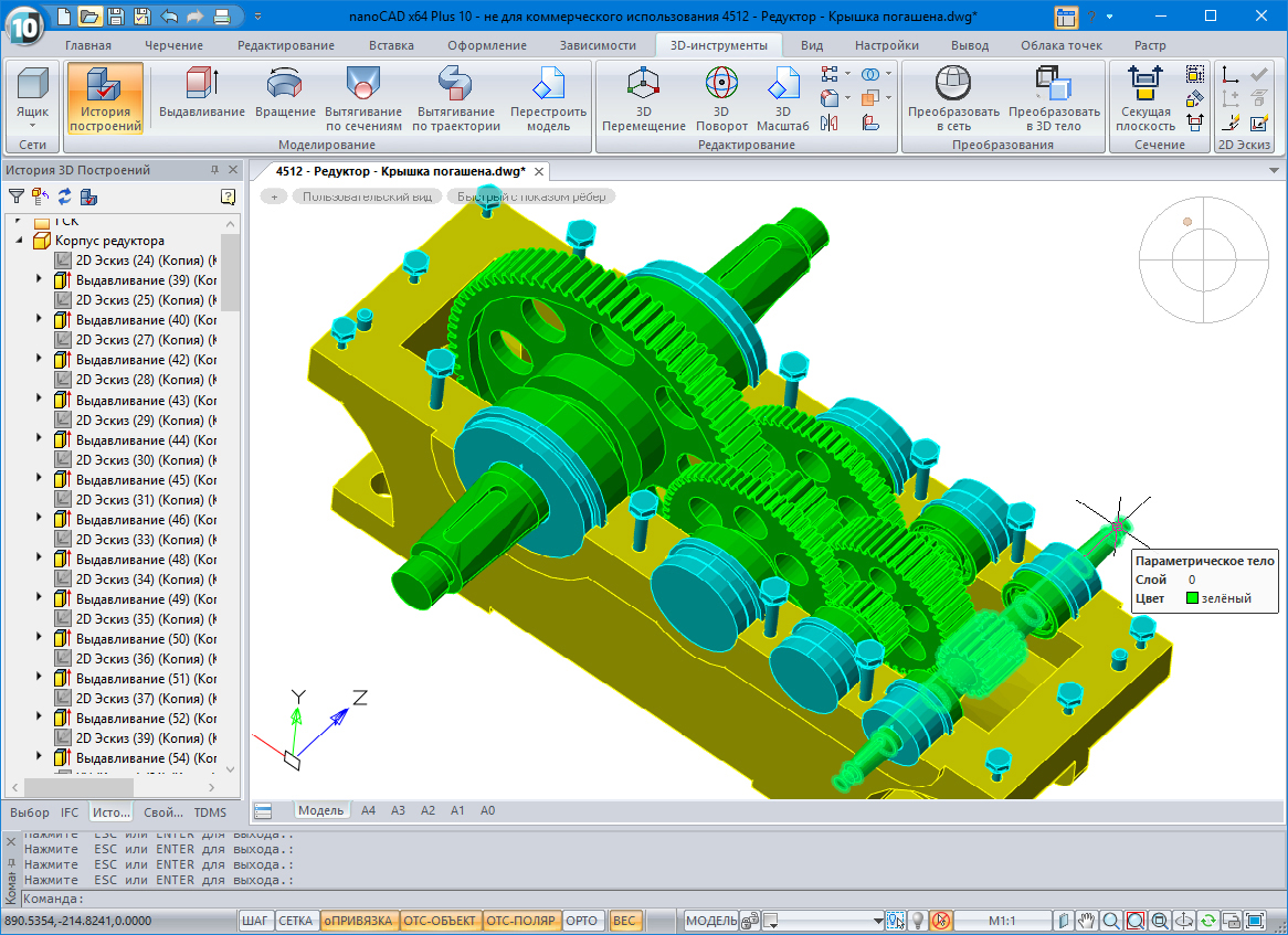
Another well-known CAD system in which the C3D Modeler core is presently present is the nanoCAD. In the article about the new nanoCAD Plus 10 platformdows described how the 3D modeling module works: the connection of the geometric core — C3D or ACIS — takes place at the user's choice, and our kernel is installed by default.
nanoCAD Plus with a 3D modeling module on C3D
In order to translate into C3D, operations that were previously performed on ACIS, it was necessary to overcome more than one barrier. Changing the 3D core entails changing the data of associative links, changing the orientation of faces and edges, changing the type of geometry of edges, changing the topology of the body when building, changing the topology of the body when changing the format of the 3D model, deviating the geometry of complex surfaces. All this, the developers of Nanosoft managed to win.
EDA / Electronics Design
If mechanical CAD systems have moved to the paradigm of three-dimensional design for a long time, then for CAD electronic devices 3D becomes mainstream only now. World and Russian developers are here in approximately equal positions in terms of the capabilities of their products. And what is nice for us is that both work with our core.
A year ago, Altium, the developer of the worldwide popular Altium Designer (successor to P-CAD), licensed the C3D Toolkit, and in the near future a new version of Altium Designer should be released, in which 3D modeling has already been done with our tools.
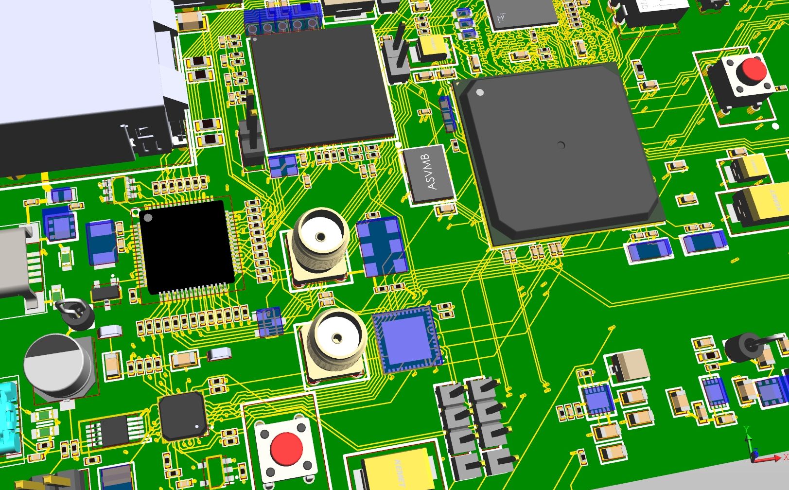
In parallel with the Altium, the Russian company Eremex is developing a system for designing printed circuit boards Delta Design, based on the geometric core C3D Modeler.
PCB model in Delta Design
For Delta Design we had to solve the problem of visualization of printed circuit boards with a large number of layers and components - to speed up operations with regions in the core.
CAE / Engineering Analysis and Calculations
Industrial design engineers are well acquainted with NTP Pipeline and its products START, PASSAT, Union-FEM. Since 2014, in the PASSAT program, which performs the strength calculations of vessels and devices, all elements of the 3D model are created on the C3D Modeler core, and this is a fairly large list: cylindrical shells and conical transitions, welded bottoms and detachable covers, reinforcement holes, tie-ins into the shells and convex bottoms, flange connections, etc.
The kernel is also responsible for calculating the geometric characteristics (volume, surface area, center of gravity, moment of inertia), and the C3D Converter converters are responsible for exporting models to the ACIS, IGES, Parasolid, and STEP formats.
PASSAT
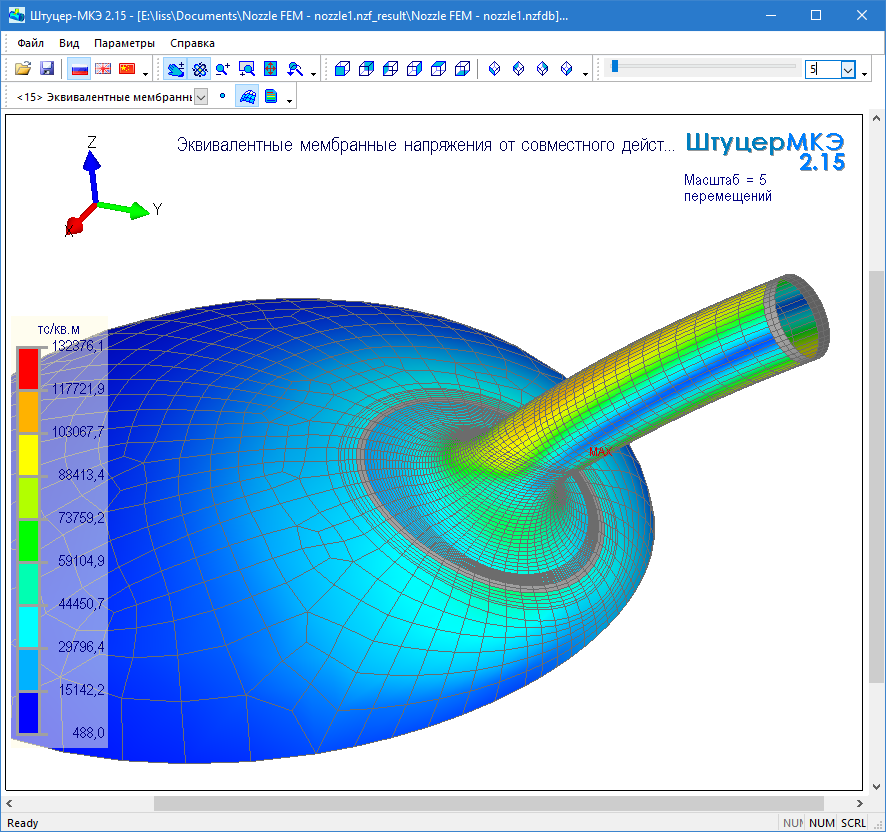
This year, NTP Pipeline connected the core to its second product, Fitting-FEM (strength calculations for tie-in units in equipment), but not yet for all geometric operations. Due to the nature of the models, difficulties have arisen with Boolean operations and the projection of curves onto the surface. Basically, in our core, Fitting-FEM stores curves and builds fillets.
Union-FEM
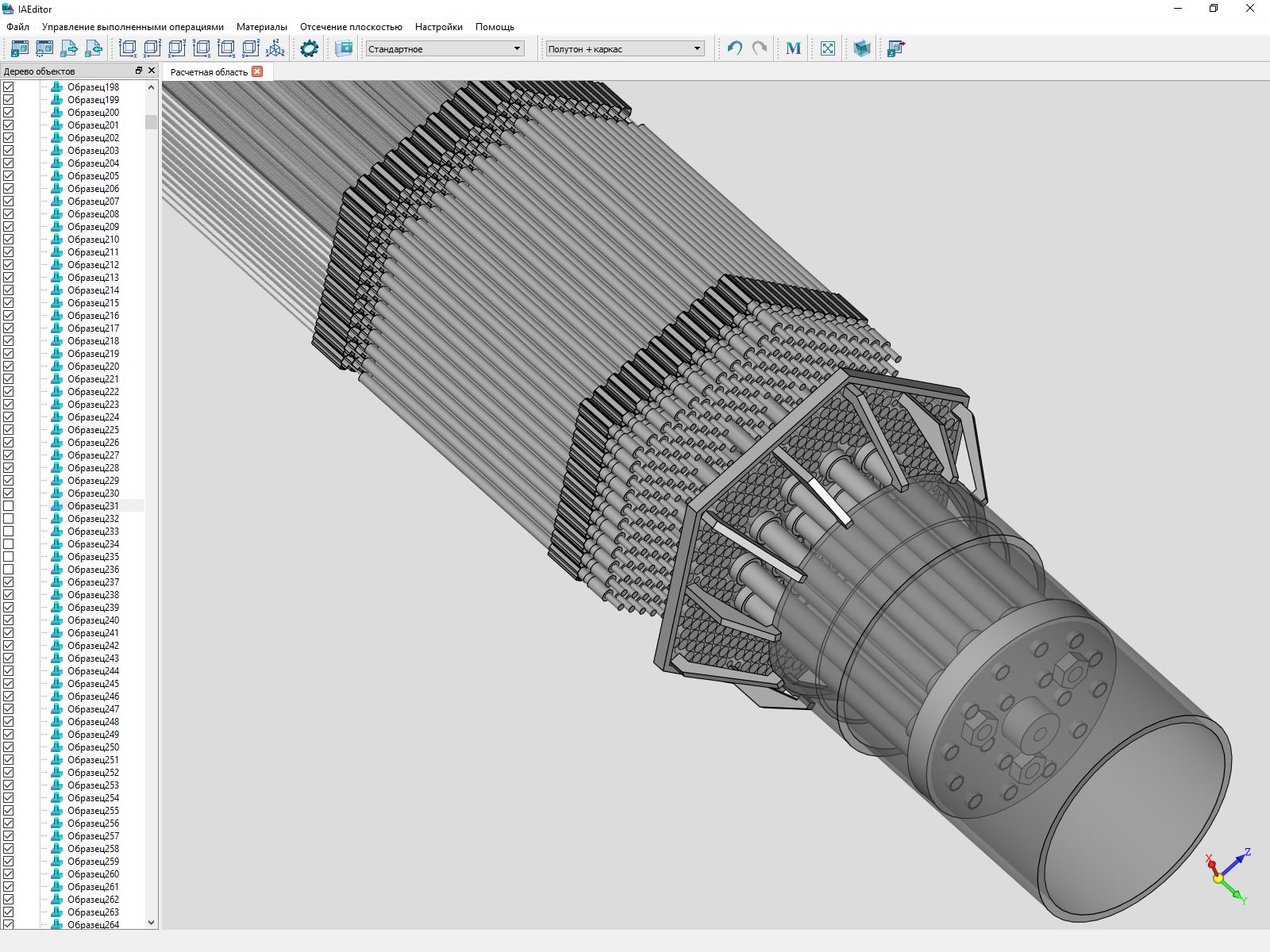
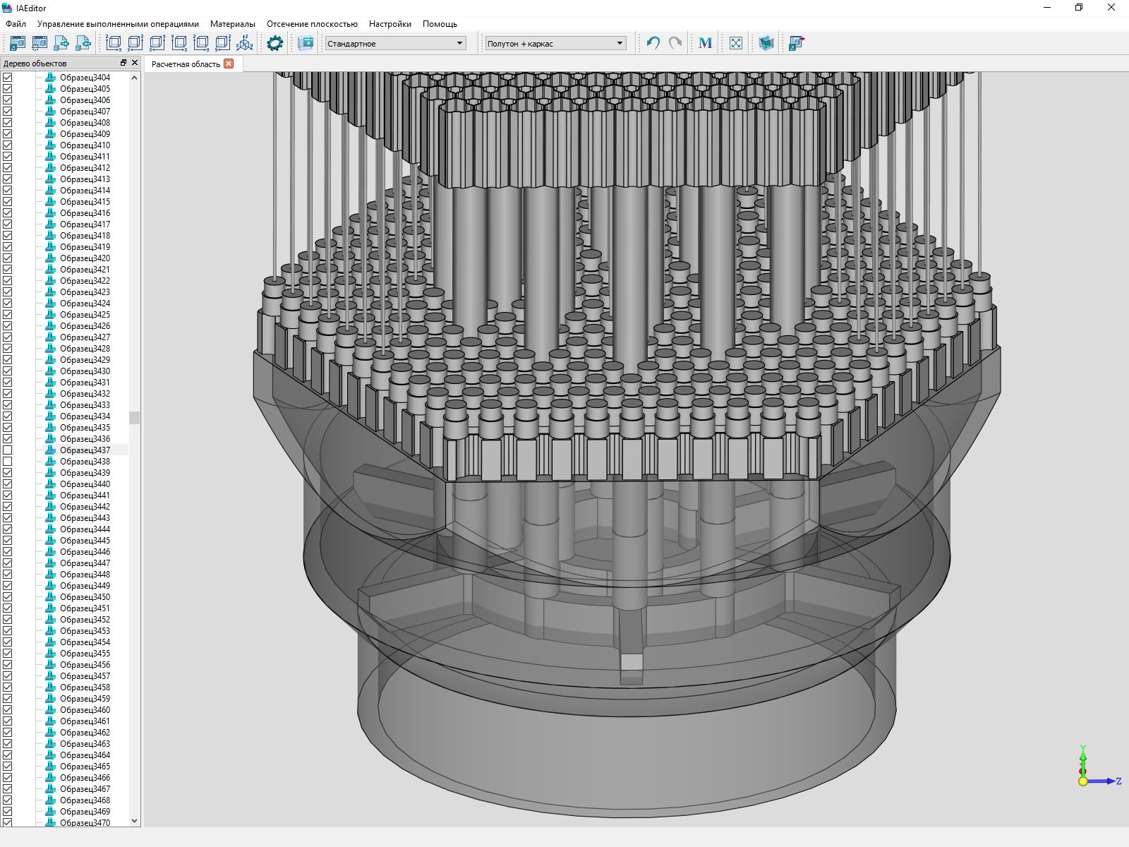
In the development of design software, it uses the C3D core and the RFNC-VNIITF nuclear center of the Rosatom State Corporation. We have no right to tell about the purpose of the product, but you can show some screenshots.
At first, our components were used in this product only for modeling geometry and importing / exporting finished geometry through exchange formats, and developers did visualization on their own components. But a year ago they switched to our C3D Vision engine. According to their assessment, the quality has improved and the output speed of the scene elements has increased. Now we are waiting for tools to create, output and work with 2D-scene.
AEC & BIM / Architecture, Construction and Information Modeling
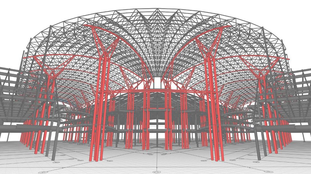
Despite external differences, in terms of the geometric core, the architecture is not much different from mechanical engineering. Therefore, when the team of Renga Software Rengabim chose which core to write its BIM, our C3D proved to be very worthy.
Now developers use core, solver and converters in three products: Renga Architecture, Renga Structure and Renga MEP. C3D tools are responsible for creating the geometry of architectural and structural objects, transforming geometry, obtaining sections and facades of buildings, editing trails and equipment connected to them, calculating masses and areas, and importing solid-state models.
The project of the kindergarten in the city of Gelendzhik in Renga Architecture
Renga Structure
Interior and Cabinet Design / Furniture and Interior Design
This group includes applications that in Russia are used to be called furniture CAD. BAZIS-Center was the first to start using the C3D core, when we did not have any documentation, no official price for the license, or the very name C3D. He described his experience of choosing and implementing the kernel in detail in x512 in the article “ Nuclear technologies in CAD .
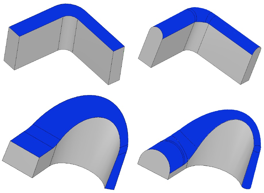
Let us single out in the article one moment related to the specifics of furniture design - modeling of curved facades. At the request of BAZIS Center, we added non-sheeting bodies to C3D Modeler. To bend any body, it is sufficient to specify the cutting plane, the number and thickness of the pieces into which the body will be broken, and for each piece, specify the location of the bend axis and its neutral layer radius. Cylindrical folds will be formed from body pieces, in which a layer spaced at a distance of a neutral radius from the axis will not experience compression or stretching. Now in CAD Basis, you can simulate curved facades with milling.
Bending non-leaf bodies
The program complex K3-Furniture for the design, production and sale of cabinet furniture is developing the Nizhny Novgorod Center GeoS. This is our only customer who uses only the parametric solver C3D Solver, without a geometric core. It is used to program the visualization of the kinematics of various furniture mechanisms, for example, lift elevators.
K3-Furniture
Mobile & Cloud / Mobile and cloud applications
Among our customers, there are still few followers of cloud technologies, but if they decide to go on this road, then we also have this experience.
For example, on the C3D Modeler core, KOMPAS is implemented: 24, the Android model viewer KOMPAS-3D ( article ).
Novosibirsk company LEDAS has integrated the core with its cloud platform LEDAS Cloud Platform (LCP). The platform transfers CAD applications to the web environment and provides in the browser the functions of data storage and management, visualization, navigation, communication and collaboration.
At the request of a single American customer, we made a parametric C3D Solver for JavaScript. A product written on its basis can not only function in the browser, but also produce geometric calculations on the client side. As far as we know, not a single developer in the world has a similar solution.
PDM / Engineering Data Management
For the convenience of work and information exchange in PDM-systems, a secondary presentation of documents is formed (a copy in a neutral format). For this, VRML, eDrawings, 3D PDF can be used. Developers LOTSMAN: PLM for 15 years tried different options and last year stopped on our viewer C3D Viewer ( article ). It allows you to view 3D models and annotate. By the way, the annotation functionality was developed by order of the LOTSMAN: PLM team and is included in the paid Enterprise version of the product. The basic C3D Viewer remains free (you can download it here ).
Secondary presentation in LOTSMAN: PLM
CAM / Production
Usually, in systems of preparation of control programs for CNC machines, the geometric core plays an important, but not the key role: it works in the preprocessor, ensuring the import of a geometric model from CAD systems and the refinement of geometry before programming processing. In essence, the core is needed to saturate CAM systems with CAD functionality demanded by technologists. Do not do without the 3D-core and developers of integrated CAD / CAM solutions.
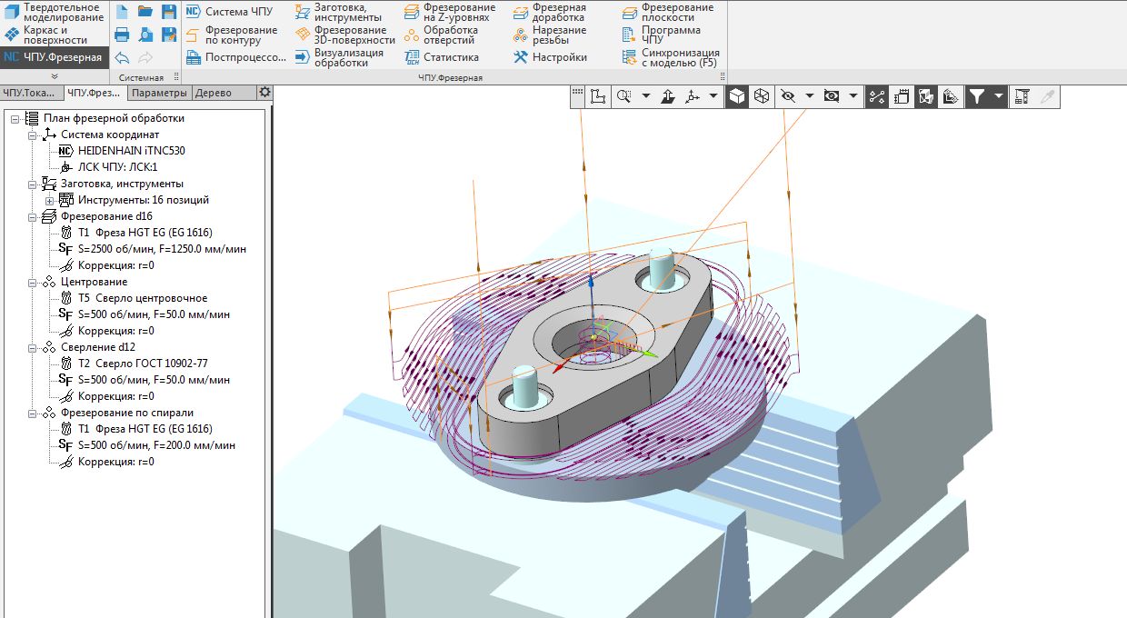
At Mordovia State University, a long-standing team on the CAM-direction. First they wrote “CNC module. Turning ”on API KOMPAS, and later -“ CNC module. Milling ”for 2.5 and 3-axis machining directly on the C3D core. Their path is different from the traditional approach of CAM developers to the core.
The application is integrated into the KOMPAS-3D workspace and uses the CAD model created in KOMPAS as a source of geometric information. With the help of C3D functions, spatial areas of material removal, their subtraction from the workpiece, the construction of three-dimensional trajectories are modeled. The specificity of using C3D for CAM tasks is that such complex geometric modeling operations as building shells, finding intersection curves, Boolean operations, are not the ultimate modeling objects (as in CAD systems), but are elementary bricks for implementing high-level algorithms for the CAM area. This imposes additional requirements for the coordination of the accuracy of the results obtained through the kernel, with the overall accuracy of calculations in the framework of high-level tasks.
CNC module. Milling
Interested developers can test the C3D Toolkit themselves. All components are provided free of charge for three months, with documentation, upon request on our website.