How the cooling system of the data center NORD-4 was created
At the end of September, the NORD-4 data center cooling system project received the Russian Data Center Awards 2016 in the nomination “The Best Solution in the Field of Engineering Systems” . Today we will tell you in detail how the cooling system of the largest data center in Russia was created.
Type of building. NORD-4 was immediately planned to be multi-storey: on the first floor of the data center there is an energy center, on the second and third - 8 rooms for 2016 rack seats.
Cooling capacity. At least 10,000 kW of cooling capacity was required to remove heat from IT equipment with a capacity of 9000 kW and related engineering infrastructure.
The temperature in the room . In the cold corridors of the machine room, the temperature should be between 23–27 ° С. In such conditions, the equipment works stably, and engineers in cold corridors do not catch a cold.
Climatic conditions on the street.The outdoor temperature for the project is taken from building codes (SNiP). In the Moscow region in winter the temperature drops to –42 ° С, and in the warm season reaches +37 ° С.
Certification The data center was planned to be certified according to the standards of the Uptime Institute Tier III (design, finished building and operation processes). According to the standard, in the Tier III level data center, any system component can be turned off for maintenance without interruption. This means that each element has a margin of at least N + 1.
Launch schedule. The data center was immediately built with an eye to phased launch, so all systems had to be designed so that the installation and commissioning of new capacities did not interfere with existing machine rooms.
Type of IT equipment.NORD-4 is a commercial data center: it will be filled gradually and with a variety of racks. This means that you cannot rigidly fix the layout of the racks in the engine room and pre-isolate hot or cold corridors.
Before dwelling on the chiller circuit, which was implemented, we examined several alternatives.
Direct expansion air conditioners (DX). This configuration is often called simply freon. In the machine rooms are cabinet freon air conditioners with an evaporator, compressor, and thermostatic valve. On the roof or next to the data center building - external units with a capacitor. Air conditioners and external units are interconnected by copper freon conduits.
In this scheme, the air conditioner cools the air directly in the engine room without an intermediate coolant (water, air).
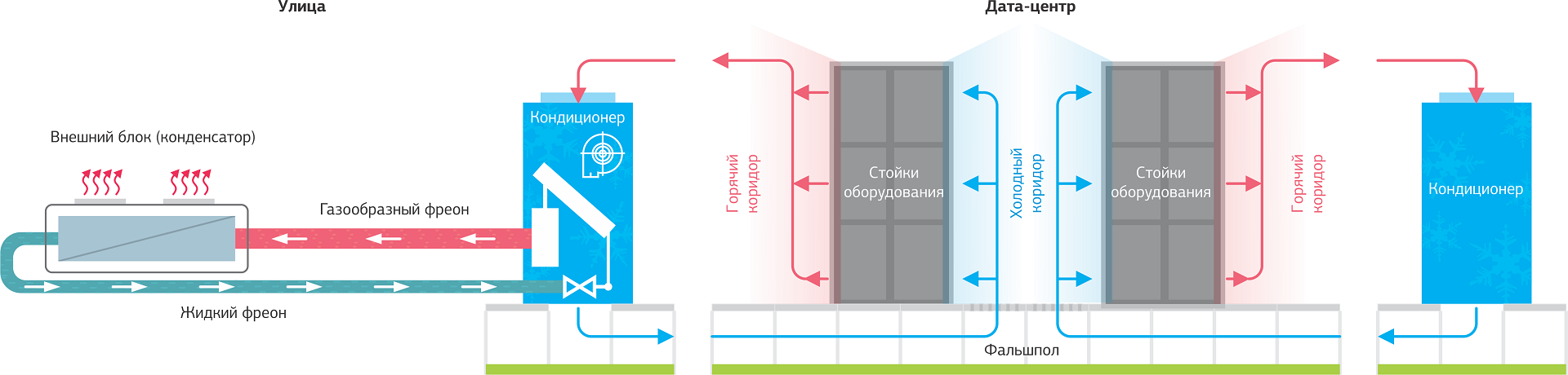
The principle of operation of the freon cooling circuit.
This system works in 5 of our data centers, so it is familiar to us. Compared with the chiller scheme, it has a number of advantages: it is cheaper in terms of capital investments, easier and faster to install. Since all air conditioners are autonomous, to back up the system it is enough to add the right amount of extra air conditioners.
Despite these advantages, it did not fit the NORD-4 project due to the following restrictions:
Kyoto Cooling. This is a dual-circuit circuit with natural air cooling (free cooling). Data center air circulates in the internal circuit, and street air is supplied to the external circuit. In a rotary heat exchanger-recuperator, or “wheel”, hot air from IT equipment is cooled by street air. Kyoto Cooling does not involve compressors (the same natural cooling) at low street temperatures.
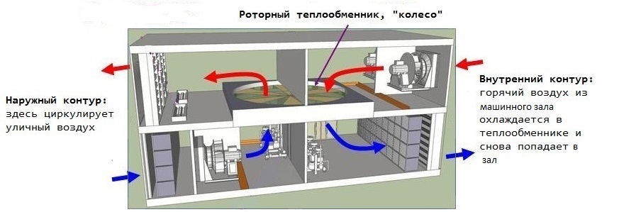
The principle of operation of Kyoto Cooling.
This option bribed with its energy efficiency: in the freecooling mode, electricity is consumed only on the drive of fan motors. Data centers using this scheme can boast one of the lowest PUEs - 1.09–1.13. Unlike the chiller scheme, Kyoto Cooling works without water, so there is no risk of leaks.
At the same time, the Kyoto Cooling system presented specific building planning requirements:
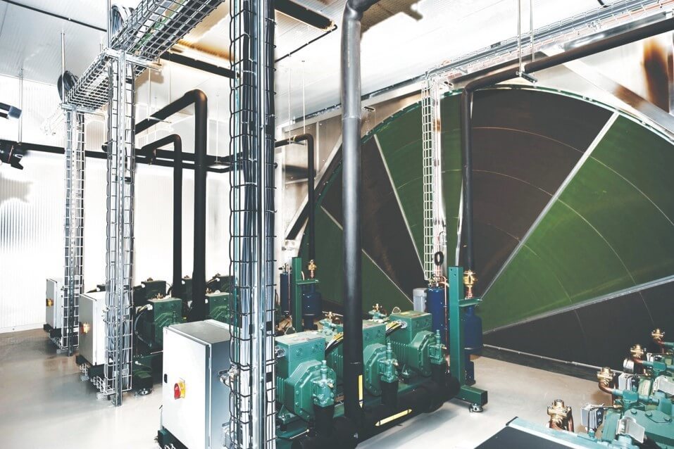
"Wheel" with a horizontal axis.
At a cost, the system was expensive. In order for Kyoto Cooling to cope with cooling only due to street air, the street should not be hotter than 25 ° С. For the summer period, in addition to the “wheel”, we would still have to purchase refrigeration machines at full capacity. In addition, the solution was new and untested for us, and I did not want to experiment in such a large-scale facility.
Chiller fan coil.Another alternative was the double-circuit chiller scheme based on ethylene glycol and water. An external circuit with a non-freezing ethylene glycol solution connects the chillers and the heat exchanger. The internal circuit with water goes from the heat exchanger to the cabinet air conditioners. Thus, the air in the engine rooms is cooled using coolants - water and ethylene glycol solution.
We used a similar scheme in our very first data center OST-1. The possibility of natural cooling in the cold season is the main advantage of this scheme. When freezing, only fans and pumps consume electricity. Compressors, the most "gluttonous" element of the system, are turned off.
The chiller circuit looked like the most suitable option for the NORD-4 project. It did not rest against restrictions, like a freon circuit, and in the long run was more energy efficient. Unlike Kyoto Cooling, it did not require special solutions in the layout of the building, but at the same time also supported the free-cooling mode.
Chillers. We analyzed the energy and economic efficiency of equipment with close technical parameters: from the cost of the equipment and its estimated energy consumption during the year it was calculated how soon the difference in price compared to the cheapest model would be eliminated due to energy savings. In fact, we compared CAPEX and OPEX. As a rule, it turned out that the more expensive the car, the longer it worked in the free-cooling mode and the less electricity it consumed during the year. Thanks to this comparison, we saw that the payback period for expensive models is comparable to cheaper ones.
Viewed the equipment of more than 10 vendors: Emerson, Uniflair, Stulz, Climaventa, Hiref, Aermec, Climacore, Clivet, Hitema, Clint, Ferroli. According to the results of our research, the Stulz CyberCool-2 chiller with a nominal cooling capacity of 950 kW turned out to be the most suitable for our purposes. The chiller operates on a “warm” coolant: the temperature of ethylene glycol at the outlet of the chiller is 16 ° C, at the inlet - 22 ° C. Typically, the temperature of ethylene glycol is +7 and +12 ° C.
The high temperature of the coolant provides a longer period of natural cooling due to street air. If ethylene glycol is warmer than outside air, the cooling system removes heat without turning on the compressors.
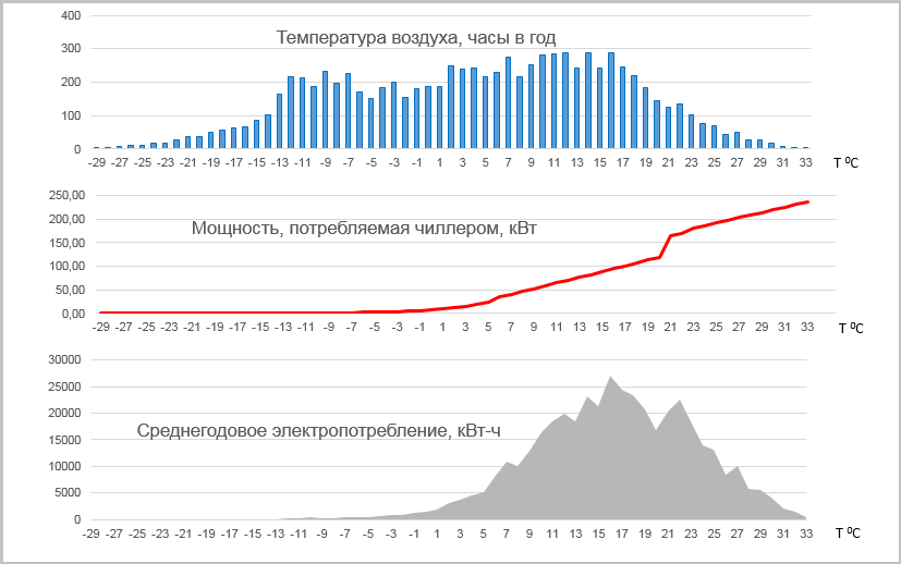
Energy Efficiency Analysis of the Stulz CyberCool-2 Chiller.
The chiller enters the full freecooling mode when it is cooler than +6 ° С in the street, and into partial mode - at temperatures from +6 to +19 ° С. With full freecooling, compressors are turned off, and only fans and pumps consume electricity.
The chiller's cooling capacity is regulated thanks to 4-speed screw compressors. They work in four modes and can vary performance: 0, 25, 50,100%. Power is also regulated by electronically-switched fans.
The chiller controller is powered by the built-in UPS, therefore, when switching the power in the data center, it continues to work and does not waste time rebooting.
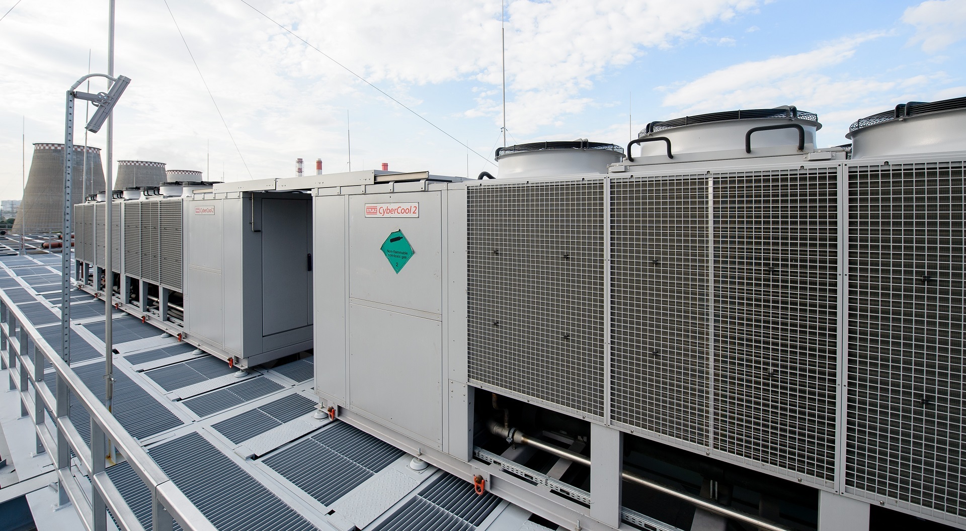
Chillers Stulz CyberCool-2.
Air conditioners.As is the case with chillers, more expensive models of air conditioners turned out to be more energy efficient. It happened with Stulz ASD1000CW as a result. According to our calculations, the high cost of the Stulz air conditioner is compensated in less than a year by the use of fans with electronic switching.
The water temperature at the inlet to the air conditioner is 18 ° C, at the outlet - 24 ° C. Due to the high temperature of the coolant in the system, the air conditioners operate above the dew point, so no extra energy is spent on moisture condensation and subsequent air humidification.

Air conditioning Stulz ASD1000CW.
Each air conditioner regulates cooling capacity with a 2-way valve, changing the flow rate of water (variable flow diagram). In a more common constant-flow scheme, the air conditioner regulates the air temperature using a 3-way valve, passing part of the water through the heat exchanger and part through the bypass. At the outlet of the air conditioner, the flows are mixed. In our scheme, this does not happen, and it turns out to maintain a high temperature of return water.
At a variable flow rate, the pumps maintain a constant pressure at the inlets of the air conditioners. This is followed by an automatic control system.
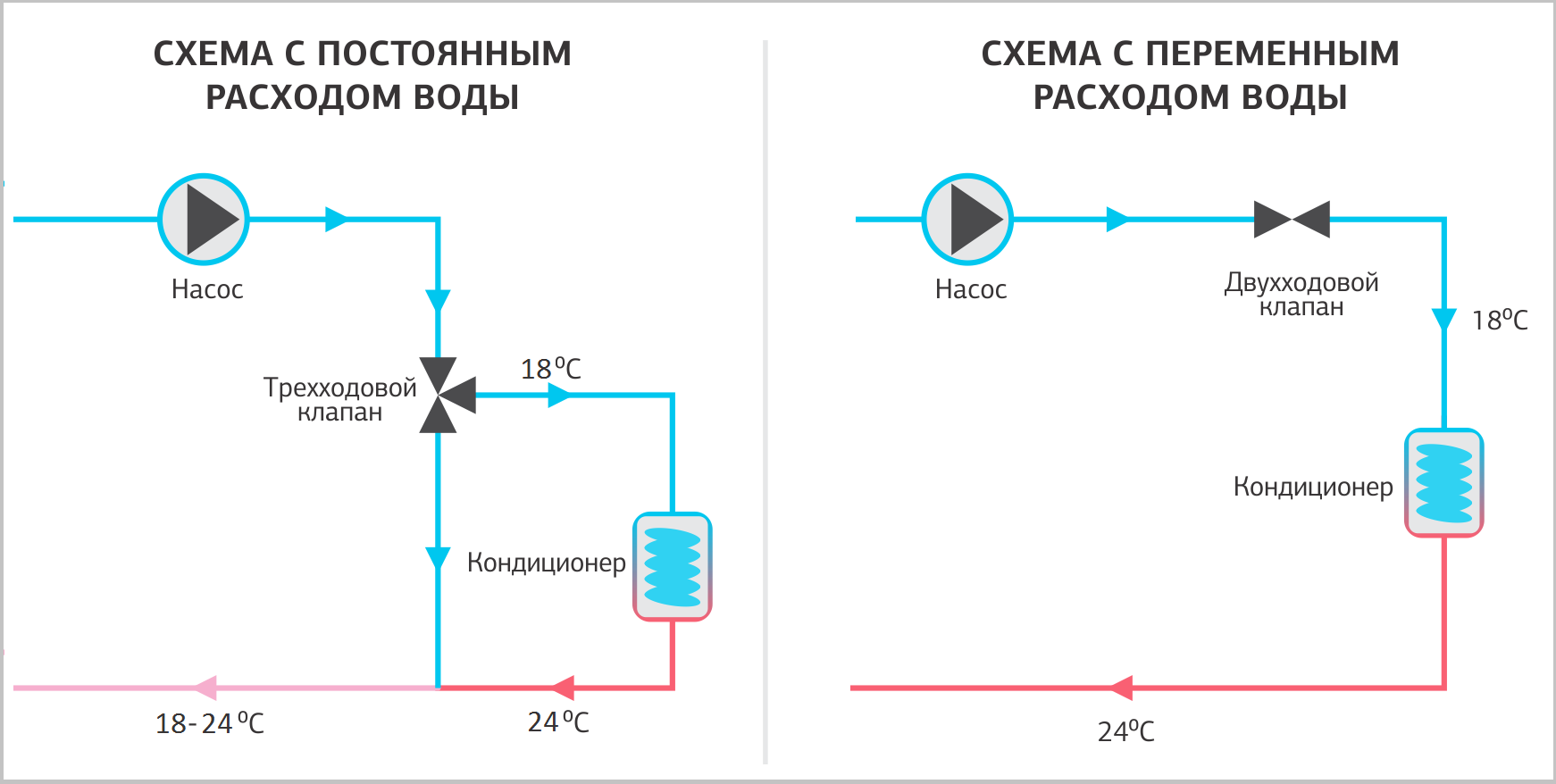
Comparison of schemes with constant and variable water flow.
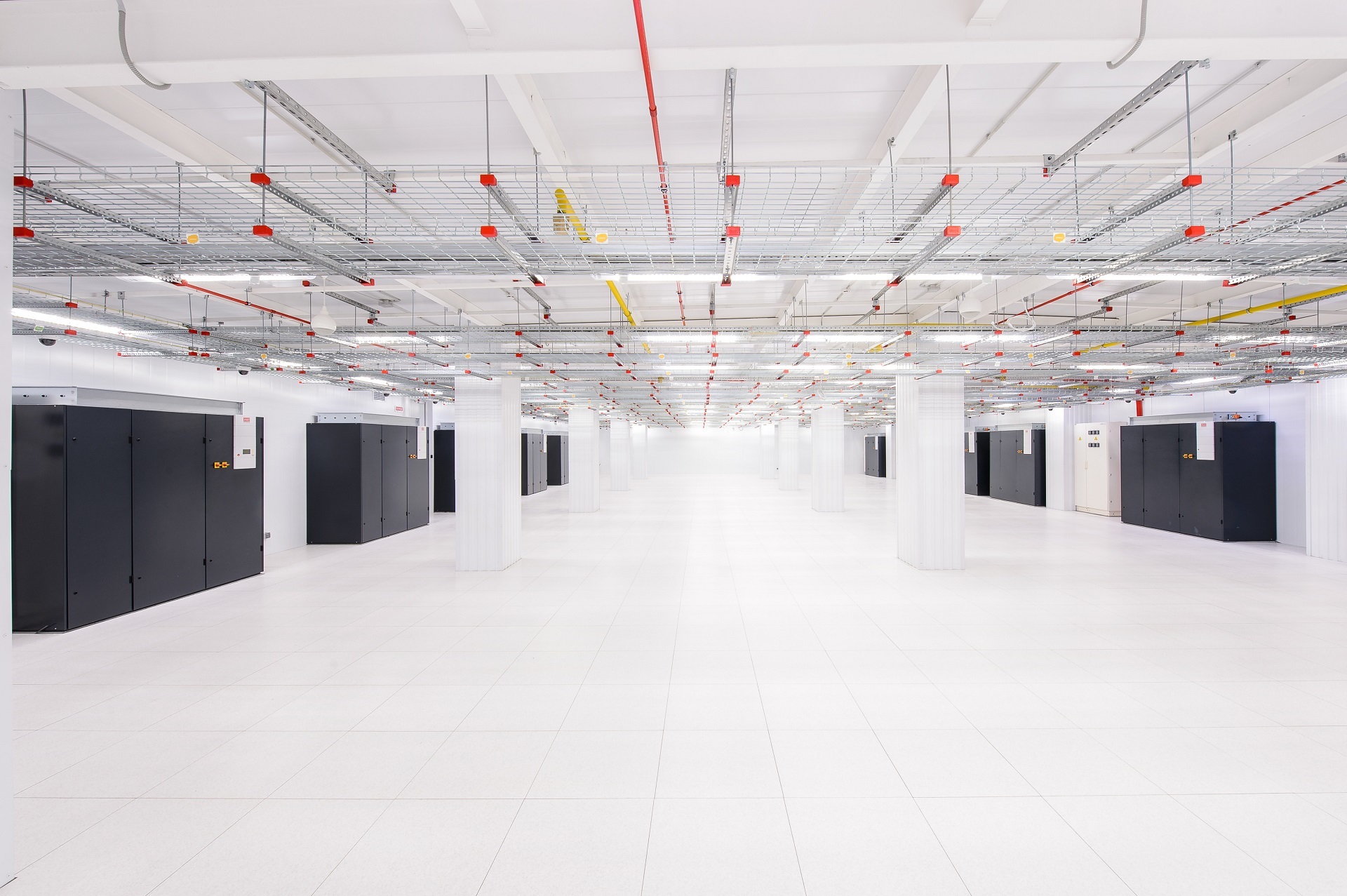
There are 14 air conditioners in each engine room, and 4 in the energy centers. Redundancy scheme N + 1.
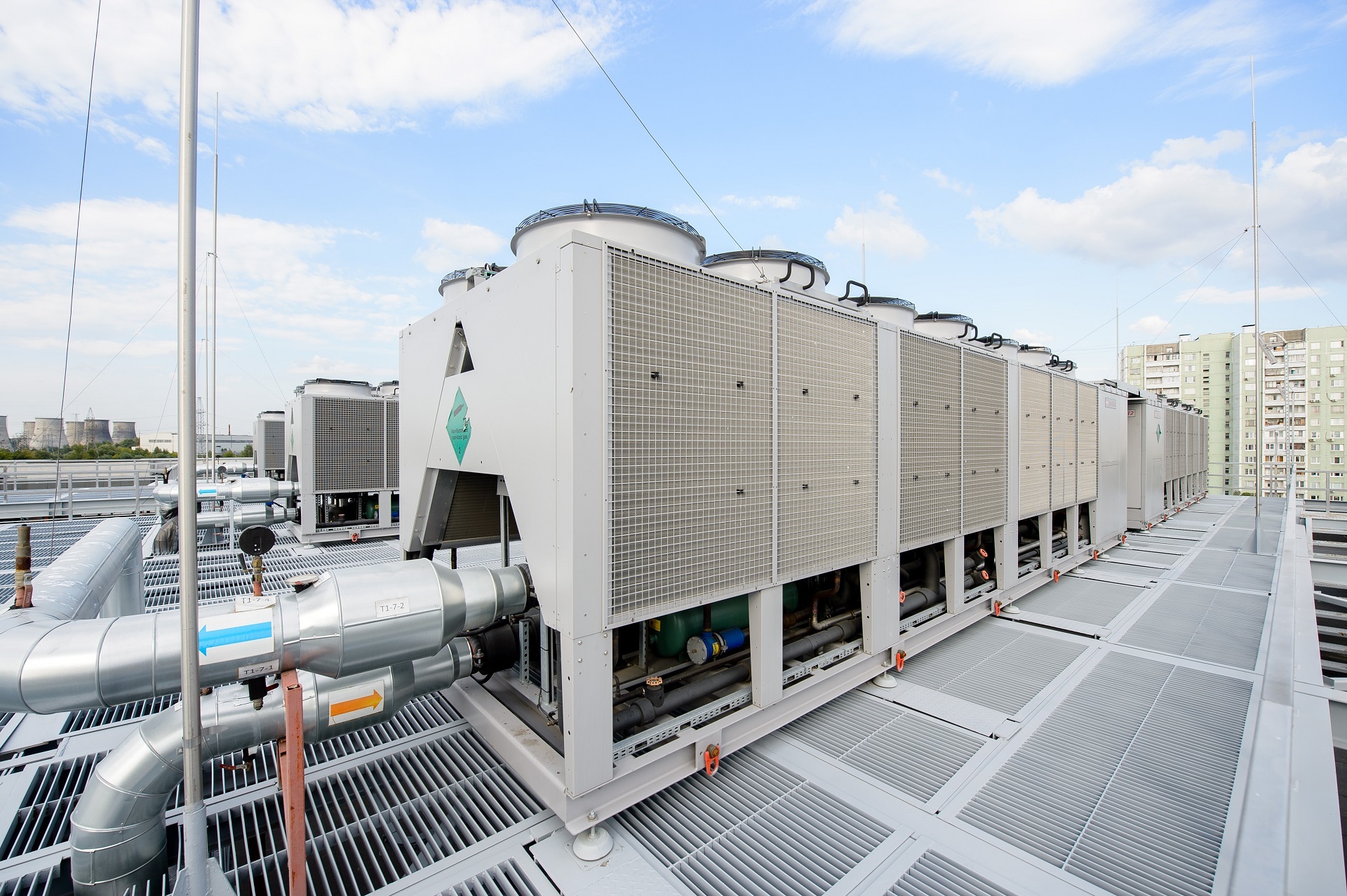
There are 14 chillers on the roof of the data center. Chiller groups will be mounted in four stages in accordance with the launch of machine rooms: 4 + 3 + 4 + 3. At each stage, a reserve of at least N + 1 is maintained: 3 + 1, 6 + 1, 9 + 2, 12 + 2. To date, 7 chillers (6 + 1) have been installed.
We placed all other elements of the system in a refrigeration center on the fourth technical floor above the engine rooms. There are pumps, storage tanks, the main shut-off and control valves, intermediate heat exchangers, piping of water and glycol circuits of the cooling system. So we simplified the management of valves, unloaded the floors with machine rooms and secured ourselves from large-scale leaks near IT equipment. The technical floor is waterproofed and equipped with 24 emergency funnel drainage systems. In the event of an accident, all spilled liquid is removed from the technical floor through pipes to the basement, in special storage tanks. Leakage sensors are included with each air conditioner, and there is also a network of independent sensors for the monitoring system.
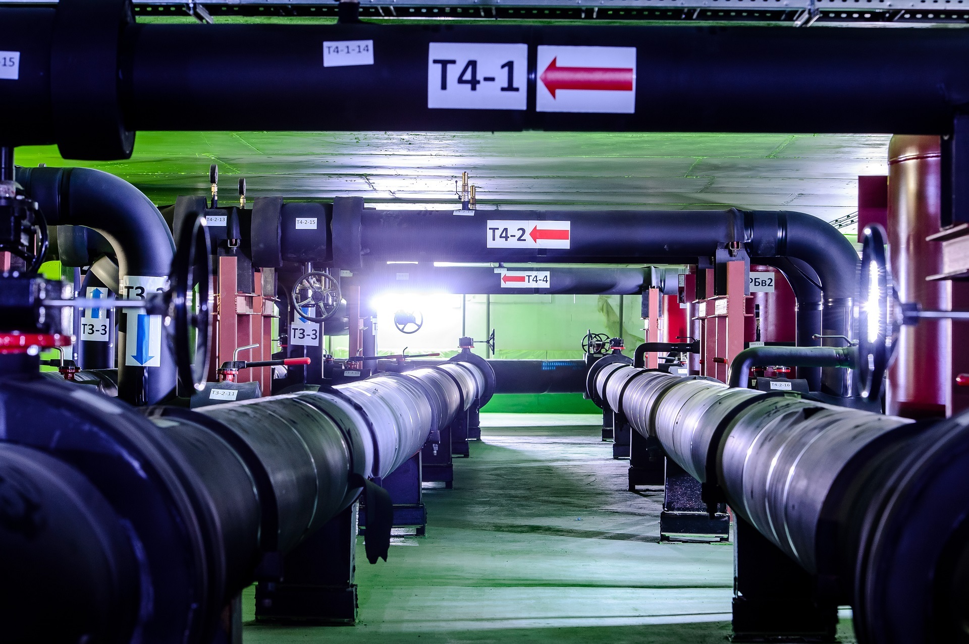
Technical floor.
An external circuit with a solution of ethylene glycol connects the chiller and the heat exchanger: warm glycol with a temperature of 22 ° C goes to the chiller, is cooled to 16 ° C and enters the heat exchanger. Each chiller with pump, piping and heat exchanger forms an independent refrigeration unit. If one of the elements fails, the entire node is taken out of operation.
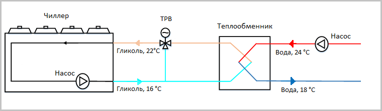
The interaction of the external and internal circuits in the chiller circuit.
The internal water circuit, which occupies the entire technical floor, connects the heat exchanger with air conditioners: water with a temperature of 18 ° C flows to the air conditioners, 24 ° C water returns from the air conditioners to the heat exchanger.
In an internal contour storage tanks with a total volume of 46 cubic meters are provided. m. During breaks in the operation of the chillers (for example, when switching from the city to DGU) These tanks support autonomous system operation for up to 8 minutes. It turns out a kind of "uninterrupted cooling."
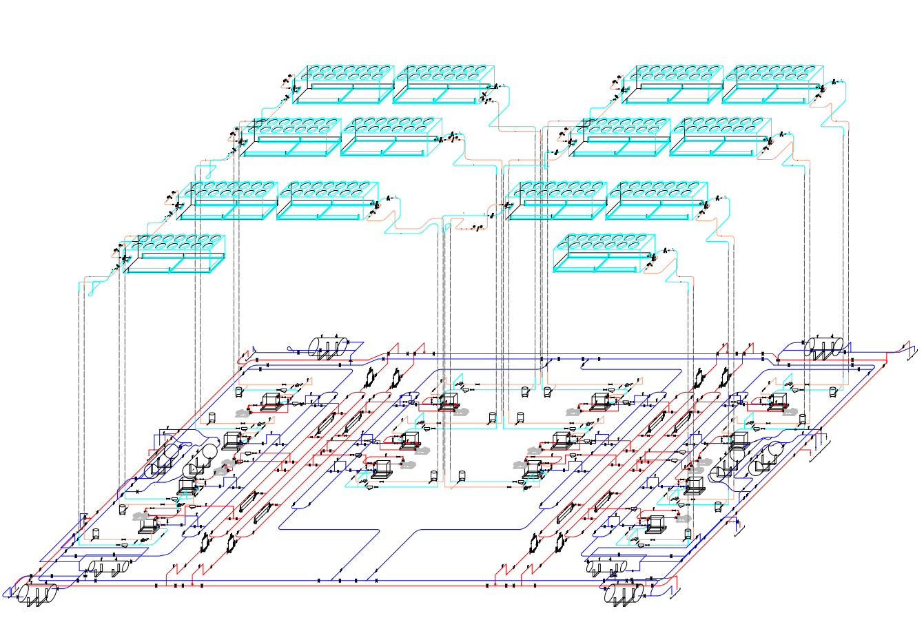
Roof with chillers and technical floor.
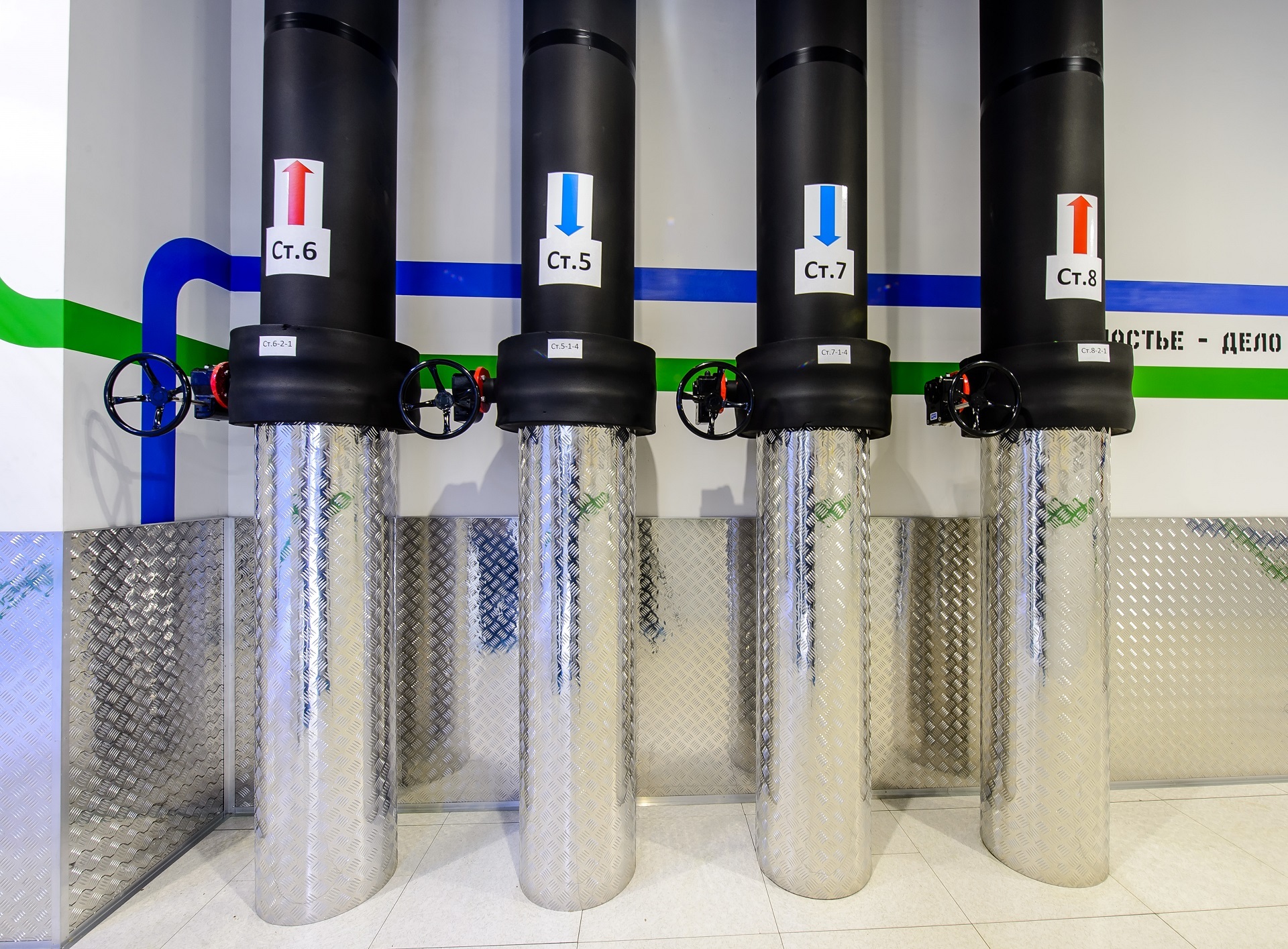
Pipelines of the internal circuit on one of the floors of NORD-4.
The main advantage of the resulting refrigeration system is its high energy efficiency. This was achieved thanks to the following solutions:
According to our calculations, at full design load of the data center, the average annual mechanical PUE (“in the cold”) will be no more than 1.21.
The conditions of the problem are as follows
Type of building. NORD-4 was immediately planned to be multi-storey: on the first floor of the data center there is an energy center, on the second and third - 8 rooms for 2016 rack seats.
Cooling capacity. At least 10,000 kW of cooling capacity was required to remove heat from IT equipment with a capacity of 9000 kW and related engineering infrastructure.
The temperature in the room . In the cold corridors of the machine room, the temperature should be between 23–27 ° С. In such conditions, the equipment works stably, and engineers in cold corridors do not catch a cold.
Climatic conditions on the street.The outdoor temperature for the project is taken from building codes (SNiP). In the Moscow region in winter the temperature drops to –42 ° С, and in the warm season reaches +37 ° С.
Certification The data center was planned to be certified according to the standards of the Uptime Institute Tier III (design, finished building and operation processes). According to the standard, in the Tier III level data center, any system component can be turned off for maintenance without interruption. This means that each element has a margin of at least N + 1.
Launch schedule. The data center was immediately built with an eye to phased launch, so all systems had to be designed so that the installation and commissioning of new capacities did not interfere with existing machine rooms.
Type of IT equipment.NORD-4 is a commercial data center: it will be filled gradually and with a variety of racks. This means that you cannot rigidly fix the layout of the racks in the engine room and pre-isolate hot or cold corridors.
Choice of cooling scheme
Before dwelling on the chiller circuit, which was implemented, we examined several alternatives.
Direct expansion air conditioners (DX). This configuration is often called simply freon. In the machine rooms are cabinet freon air conditioners with an evaporator, compressor, and thermostatic valve. On the roof or next to the data center building - external units with a capacitor. Air conditioners and external units are interconnected by copper freon conduits.
In this scheme, the air conditioner cools the air directly in the engine room without an intermediate coolant (water, air).
The principle of operation of the freon cooling circuit.
This system works in 5 of our data centers, so it is familiar to us. Compared with the chiller scheme, it has a number of advantages: it is cheaper in terms of capital investments, easier and faster to install. Since all air conditioners are autonomous, to back up the system it is enough to add the right amount of extra air conditioners.
Despite these advantages, it did not fit the NORD-4 project due to the following restrictions:
- length of freon pipelines: for effective cooling, it should not exceed 50 meters horizontally, if there is a height difference - even less. With a multi-story data center, it was difficult to meet these restrictions.
- low energy efficiency: in the long run, the freon circuit is less profitable than the same chiller. The freon air conditioning compressor has only two states - on and off. In such a scheme, there is no possibility of cooling without a running compressor, that is, electricity for cooling will be consumed even when it is cold outside.
Kyoto Cooling. This is a dual-circuit circuit with natural air cooling (free cooling). Data center air circulates in the internal circuit, and street air is supplied to the external circuit. In a rotary heat exchanger-recuperator, or “wheel”, hot air from IT equipment is cooled by street air. Kyoto Cooling does not involve compressors (the same natural cooling) at low street temperatures.
The principle of operation of Kyoto Cooling.
This option bribed with its energy efficiency: in the freecooling mode, electricity is consumed only on the drive of fan motors. Data centers using this scheme can boast one of the lowest PUEs - 1.09–1.13. Unlike the chiller scheme, Kyoto Cooling works without water, so there is no risk of leaks.
At the same time, the Kyoto Cooling system presented specific building planning requirements:
- the heat exchanger “wheel” with all ventilation chambers takes up a lot of space. In fact, you need a separate technical room for it, which is difficult to fit into the finished building project.
- air has a small heat capacity: large air ducts are needed to transfer a large amount of heat. The function of the ducts can be performed by corridors, but this again must be provided for at the design stage of the building.
- hot hallways must be insulated inside the machine room. This is difficult to do when the racks are of various sizes and the hall is filling up gradually.
- additional costs for filters. The street air that comes to the wheel needs to be filtered, otherwise the dust will fall into the engine rooms.
"Wheel" with a horizontal axis.
At a cost, the system was expensive. In order for Kyoto Cooling to cope with cooling only due to street air, the street should not be hotter than 25 ° С. For the summer period, in addition to the “wheel”, we would still have to purchase refrigeration machines at full capacity. In addition, the solution was new and untested for us, and I did not want to experiment in such a large-scale facility.
Chiller fan coil.Another alternative was the double-circuit chiller scheme based on ethylene glycol and water. An external circuit with a non-freezing ethylene glycol solution connects the chillers and the heat exchanger. The internal circuit with water goes from the heat exchanger to the cabinet air conditioners. Thus, the air in the engine rooms is cooled using coolants - water and ethylene glycol solution.
We used a similar scheme in our very first data center OST-1. The possibility of natural cooling in the cold season is the main advantage of this scheme. When freezing, only fans and pumps consume electricity. Compressors, the most "gluttonous" element of the system, are turned off.
The chiller circuit looked like the most suitable option for the NORD-4 project. It did not rest against restrictions, like a freon circuit, and in the long run was more energy efficient. Unlike Kyoto Cooling, it did not require special solutions in the layout of the building, but at the same time also supported the free-cooling mode.
Equipment selection
Chillers. We analyzed the energy and economic efficiency of equipment with close technical parameters: from the cost of the equipment and its estimated energy consumption during the year it was calculated how soon the difference in price compared to the cheapest model would be eliminated due to energy savings. In fact, we compared CAPEX and OPEX. As a rule, it turned out that the more expensive the car, the longer it worked in the free-cooling mode and the less electricity it consumed during the year. Thanks to this comparison, we saw that the payback period for expensive models is comparable to cheaper ones.
Viewed the equipment of more than 10 vendors: Emerson, Uniflair, Stulz, Climaventa, Hiref, Aermec, Climacore, Clivet, Hitema, Clint, Ferroli. According to the results of our research, the Stulz CyberCool-2 chiller with a nominal cooling capacity of 950 kW turned out to be the most suitable for our purposes. The chiller operates on a “warm” coolant: the temperature of ethylene glycol at the outlet of the chiller is 16 ° C, at the inlet - 22 ° C. Typically, the temperature of ethylene glycol is +7 and +12 ° C.
The high temperature of the coolant provides a longer period of natural cooling due to street air. If ethylene glycol is warmer than outside air, the cooling system removes heat without turning on the compressors.
Energy Efficiency Analysis of the Stulz CyberCool-2 Chiller.
The chiller enters the full freecooling mode when it is cooler than +6 ° С in the street, and into partial mode - at temperatures from +6 to +19 ° С. With full freecooling, compressors are turned off, and only fans and pumps consume electricity.
The chiller's cooling capacity is regulated thanks to 4-speed screw compressors. They work in four modes and can vary performance: 0, 25, 50,100%. Power is also regulated by electronically-switched fans.
The chiller controller is powered by the built-in UPS, therefore, when switching the power in the data center, it continues to work and does not waste time rebooting.
Chillers Stulz CyberCool-2.
Air conditioners.As is the case with chillers, more expensive models of air conditioners turned out to be more energy efficient. It happened with Stulz ASD1000CW as a result. According to our calculations, the high cost of the Stulz air conditioner is compensated in less than a year by the use of fans with electronic switching.
The water temperature at the inlet to the air conditioner is 18 ° C, at the outlet - 24 ° C. Due to the high temperature of the coolant in the system, the air conditioners operate above the dew point, so no extra energy is spent on moisture condensation and subsequent air humidification.
Air conditioning Stulz ASD1000CW.
Each air conditioner regulates cooling capacity with a 2-way valve, changing the flow rate of water (variable flow diagram). In a more common constant-flow scheme, the air conditioner regulates the air temperature using a 3-way valve, passing part of the water through the heat exchanger and part through the bypass. At the outlet of the air conditioner, the flows are mixed. In our scheme, this does not happen, and it turns out to maintain a high temperature of return water.
At a variable flow rate, the pumps maintain a constant pressure at the inlets of the air conditioners. This is followed by an automatic control system.
Comparison of schemes with constant and variable water flow.
Final implementation
There are 14 air conditioners in each engine room, and 4 in the energy centers. Redundancy scheme N + 1.
There are 14 chillers on the roof of the data center. Chiller groups will be mounted in four stages in accordance with the launch of machine rooms: 4 + 3 + 4 + 3. At each stage, a reserve of at least N + 1 is maintained: 3 + 1, 6 + 1, 9 + 2, 12 + 2. To date, 7 chillers (6 + 1) have been installed.
We placed all other elements of the system in a refrigeration center on the fourth technical floor above the engine rooms. There are pumps, storage tanks, the main shut-off and control valves, intermediate heat exchangers, piping of water and glycol circuits of the cooling system. So we simplified the management of valves, unloaded the floors with machine rooms and secured ourselves from large-scale leaks near IT equipment. The technical floor is waterproofed and equipped with 24 emergency funnel drainage systems. In the event of an accident, all spilled liquid is removed from the technical floor through pipes to the basement, in special storage tanks. Leakage sensors are included with each air conditioner, and there is also a network of independent sensors for the monitoring system.
Technical floor.
An external circuit with a solution of ethylene glycol connects the chiller and the heat exchanger: warm glycol with a temperature of 22 ° C goes to the chiller, is cooled to 16 ° C and enters the heat exchanger. Each chiller with pump, piping and heat exchanger forms an independent refrigeration unit. If one of the elements fails, the entire node is taken out of operation.
The interaction of the external and internal circuits in the chiller circuit.
The internal water circuit, which occupies the entire technical floor, connects the heat exchanger with air conditioners: water with a temperature of 18 ° C flows to the air conditioners, 24 ° C water returns from the air conditioners to the heat exchanger.
In an internal contour storage tanks with a total volume of 46 cubic meters are provided. m. During breaks in the operation of the chillers (for example, when switching from the city to DGU) These tanks support autonomous system operation for up to 8 minutes. It turns out a kind of "uninterrupted cooling."
Roof with chillers and technical floor.
Pipelines of the internal circuit on one of the floors of NORD-4.
findings
The main advantage of the resulting refrigeration system is its high energy efficiency. This was achieved thanks to the following solutions:
- Elevated temperature of heat carriers - ethylene glycol and water.
- Variable flow rate of the coolant in the internal water circuit. This scheme eliminates the mixing of cold and hot water. As a result, we got an increased temperature difference between hot and cold water and a longer freecooling period.
- Fans with electronic switching in cabinet air conditioners and chillers.
According to our calculations, at full design load of the data center, the average annual mechanical PUE (“in the cold”) will be no more than 1.21.