learnopengl. Lesson 1.4 - Hello Triangle
- Transfer
- Tutorial
 In the last lesson, we mastered opening a window and primitive user input. In this lesson we will analyze all the basics of displaying vertices on the screen and use all the features of OpenGL, such as VAO, VBO, EBO, in order to draw a pair of triangles.
 Interested, I ask for cat.
Content
Part 1. Getting Started
Part 2. Basic lighting
Part 3. Download 3D models
Part 4. Advanced OpenGL Features
Part 5. Advanced Lighting
- Opengl
- Window creation
- Hello window
- Hello triangle
- Shaders
- Textures
- Transformations
- Coordinate systems
- Camera
Part 2. Basic lighting
Part 3. Download 3D models
Part 4. Advanced OpenGL Features
- Depth test
- Stencil test
- Color mixing
- Clipping faces
- Frame buffer
- Cubic cards
- Advanced data handling
- Advanced GLSL
- Geometric shader
- Instancing
- Smoothing
Part 5. Advanced Lighting
In OpenGL, everything is in 3D space, but at the same time, the screen and the window are a 2D matrix of pixels. Therefore, most of the work of OpenGL is the conversion of 3D coordinates to 2D space for rendering on the screen. The process of converting 3D coordinates to 2D coordinates is controlled by the OpenGL graphics pipeline. The graphics pipeline can be divided into 2 large parts: the first part converts 3D coordinates to 2D coordinates, and the second part converts 2D coordinates to color pixels. In this lesson, we will discuss in detail the graphics pipeline and how we can use it as a plus to create beautiful pixels.
There is a difference between the 2D coordinates and the pixel. A 2D coordinate is a very accurate representation of a point in 2D space, while a 2D pixel is an approximate location within your screen / window.
The graphics pipeline takes a set of 3D coordinates and converts them into 2D color pixels on the screen. This graphic container can be divided into several stages, where each stage - requires the result of the work of the past to enter. All these stages are extremely specialized and can be easily executed in parallel. Because of their parallel nature, most modern GPUs have thousands of small processors for quickly processing graphics pipeline data by running a large number of small programs at each stage of the pipeline. These small programs are called shaders .
Some of these shaders can be customized by the developer, which allows us to write our own shaders to replace the standard ones. This gives us much more opportunities to fine-tune specific places in the pipeline, and it is precisely because they work on the GPU that allows us to save CPU time. Shaders are written in the OpenGL Shading Language (GLSL) and we will delve deeper into it in the next lesson.
In the image below you can see an approximate representation of all stages of the graphics pipeline. The blue parts describe the stages for which we can specify our own shaders.
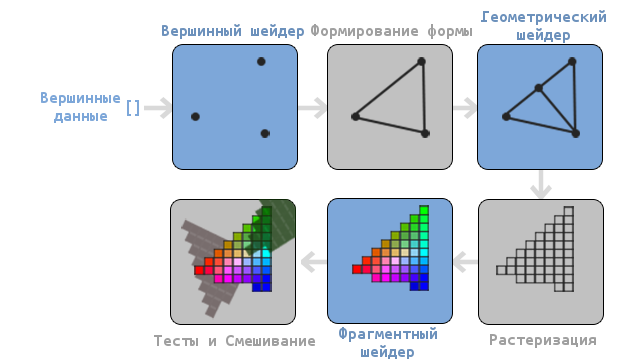
As you can see, the graphics pipeline contains a large number of sections, where each deals with its part of processing vertex data in a fully rendered pixel. We will describe each section of the conveyor in a simplified form a bit to give you a good idea of how the conveyor works.
An array of 3D coordinates is passed to the input of the conveyor from which triangles can be formed, called vertex data; vertex data is a collection of vertices. A vertex is a dataset on top of a 3D coordinate. This data is represented using the attributes of the vertex, which can contain any data, but for simplicity we assume that the vertex consists of a 3D position and color value.
Since OpenGL wants to know what to compose from a collection of coordinates and color values passed to it, OpenGL requires you to specify which shape you want to form from the data. Do we want to draw a set of points, a set of triangles, or just one long line? Such shapes are called primitives and are passed to OpenGL when invoking rendering commands. Here are some of the primitives: GL_POINTS , GL_TRIANGLES, and GL_LINE_STRIP .
The first stage of the pipeline is a vertex shader, which takes one vertex as an input. The main task of the vertex shader is to convert 3D coordinates to other 3D coordinates (more on that later) and the fact that we have the ability to change this shader allows us to perform some basic transformations on the vertex values.
Assembly of primitives is a stage that takes all the vertices (or one vertex if GL_POINTS primitive is selected ) from the vertex shader that forms the primitive and collects the primitive from them; in our case it will be a triangle.
The result of the primitive assembly phase is passed to the geometric shader. He, in turn, receives a set of vertices forming primitives at the input and can generate other shapes by generating new vertices to form new (or other) primitives. For example, in our case, he will generate a second triangle in addition to this figure.
The result of the work of the geometric shader is passed to the rasterization stage, where the resulting primitives will correspond with the pixels on the screen, forming a fragment for the fragment shader. Before the fragment shader starts, cutting is performed. It discards all fragments that are out of sight, thus increasing productivity.
A fragment in OpenGL is all the data that OpenGL needs in order to draw a pixel.
The main goal of the fragment shader is to calculate the final color of the pixel, and this is also most often the stage when all the additional OpenGL effects are performed. Often, a fragment shader contains all the information about the 3D scene, which can be used to modify the final color (such as lighting, shadows, the color of the light source, etc.).
After the determination of all the relevant color values is completed, the result will go through another step, which is called alpha testing and blending. This stage checks the corresponding value of the depth (and template) (we will return to this later) of the fragment and uses them to check the location of the fragment relative to other objects: front or back. This step also checks the transparency values and mixes the colors if necessary. Thus, during rendering of multiple primitives, the resulting color of the pixel may differ from the color calculated by the fragment shader.
As you can see, the graphics pipeline is quite complex and contains many configurable parts. Despite this, we will mainly work with the vertex and fragment shaders. A geometric shader is optional and is often left standard.
In modern OpenGL, you are forced to specify at least a vertex shader (there is no standard vertex / fragment shader on video cards). For this reason, it can often be difficult to study modern OpenGL, since you need to learn quite a lot of theory before drawing your first triangle. At the end of this tutorial, you will learn a lot about graphical programming.
Vertex transfer
In order to draw something for starters, we need to pass OpenGL vertex data. OpenGL is a 3D library and therefore all the coordinates that we tell OpenGL are in three-dimensional space (x, y and z). OpenGL does not convert all 3D coordinates passed to it into 2D pixels on the screen; OpenGL only processes 3D coordinates in a certain interval between -1.0 and 1.0 for all 3 coordinates (x, y and z). All such coordinates are called coordinates normalized to the device (or simply normalized).
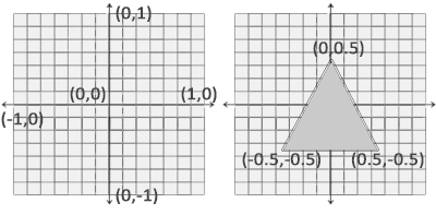
Since we want to draw one triangle, we must provide 3 vertices, each of which is in three-dimensional space. We will define them in normalized form in the GLfloat array.
GLfloat vertices[] = {
    -0.5f, -0.5f, 0.0f,
     0.5f, -0.5f, 0.0f,
     0.0f,  0.5f, 0.0f
};
Since OpenGL works with three-dimensional space, we draw a two-dimensional triangle with a z coordinate equal to 0.0. Thus, the depth of the triangle will be the same and it will look two-dimensional.
Normalized Device Coordinates (NDC)
After the vertex coordinates are processed in the vertex shader, they must be normalized to NDC, which is a small space, where x, y and z coordinates are in the range from -1.0 up to 1.0 . Any coordinates that go beyond this limit will be discarded and not displayed on the screen. Below you can see the triangle we have set:
Unlike screen coordinates, a positive y-axis value points up, and coordinates (0, 0) are the center of the graph, instead of the upper left corner.
Your NDC coordinates will then be converted to screen space coordinates through the Viewport using the data provided through the glViewport call . The coordinates of the screen space are then transformed into fragments and fed to the input to the fragment shader.
After determining the vertex data, it is required to transfer it to the first stage of the graphics pipeline: to the vertex shader. This is done as follows: we allocate memory on the GPU, where we will save our vertex data, tell OpenGL how it should interpret the data transferred to it, and transfer the amount of data transferred by us to the GPU. Then the vertex shader will process as many vertices as we told him.
We manage this memory through the so-called vertex buffer objects (VBOs), which can store a large number of vertices in the GPU memory. The advantage of using such buffer objects is that we can send a large number of data sets to the video card at a time, without the need to send one vertex at a time. Sending data from the CPU to the GPU is rather slow, so we will try to send as much data as possible at a time. But as soon as the data is in the GPU, the vertex shader will receive it almost instantly.
VBO is our first encounter with the objects described in the first lesson. Like any object in OpenGL, this buffer has a unique identifier. We can create VBOs using the glGenBuffers function :
GLuint VBO;
glGenBuffers(1, &VBO);
OpenGL has a large number of different types of buffer objects. Type VBO - GL_ARRAY_BUFFER . OpenGL allows you to bind multiple buffers if they have different types. We can bind GL_ARRAY_BUFFER to our buffer using glBindBuffer :
glBindBuffer(GL_ARRAY_BUFFER, VBO);
From now on, any call using a buffer will work with VBO. Now we can call glBufferData to copy the vertex data to this buffer.
glBufferData(GL_ARRAY_BUFFER, sizeof(vertices), vertices, GL_STATIC_DRAW);
glBufferData is a function whose purpose is to copy user data to the specified buffer. Its first argument is the type of buffer into which we want to copy the data (our VBO is now bound to GL_ARRAY_BUFFER ). The second argument determines the amount of data (in bytes) that we want to pass to the buffer. The third argument is the data itself.
The fourth argument determines how we want the video card to work with the data transferred to it. There are 3 modes:
- GL_STATIC_DRAW : data will either never change, or it will change very rarely;
- GL_DYNAMIC_DRAW : data will change quite often;
- GL_STREAM_DRAW : The data will change with every render.
The data on the position of the triangle will not change and therefore we select GL_STATIC_DRAW . If, for example, we had a buffer whose value would change very often, then we would use GL_DYNAMIC_DRAW or GL_STREAM_DRAW , thus providing the video card with information that the data of this buffer should be stored in the memory area that is the fastest to write.
Now we have saved vertex data on the GPU into a buffer object called VBO.
Next, we need to create vertex and fragment shaders for the actual data processing, so let's get started.
Vertex shader
The vertex shader is one of the programmable shaders. Modern OpenGL requires that vertex and fragment shaders be defined if we want to draw something, so we will provide two very simple shaders to draw our triangle. In the next lesson, we will discuss shaders in more detail.
At the beginning, we must write the shader itself in a special GLSL language (OpenGL Shading Language), and then assemble it so that the application can work with it. Here is the simplest shader code:
#version 330 core
layout (location = 0) in vec3 position;
void main()
{
    gl_Position = vec4(position.x, position.y, position.z, 1.0);
}
As you can see, GLSL is very similar to C. Each shader starts by installing its version. With OpenGL version 3.3 and higher, GLSL versions are the same as OpenGL versions (For example, the GLSL 420 version is the same as OpenGL version 4.2). We also explicitly indicated that we are using a core profile.
Next, we specify all the input vertex attributes in a vertex shader using the keyword in . Now we only need to work with position data, so we only specify one vertex attribute. GLSL has a vector data type containing 1 to 4 floating point numbers. Since the vertices have three-dimensional coordinates, we create vec3 called position . We also explicitly indicated the position of our variable through layout (location = 0) later you will see why we did it.
Vector
In graphical programming, we often use the mathematical concept of a vector, since it perfectly represents positions / directions in any space, and also has useful mathematical properties. The maximum size of a vector in GLSL is 4 elements, and access to each of the elements can be obtained through vec.x , vec.y , vec.z and vec.w, respectively. Note that the component vec.w is not used as a position in space (we work in 3D, not 4D), but it can be useful when working with perspective division. We will discuss vectors more deeply in the next lesson.
To indicate the result of the vertex shader, we must assign the value to the predefined variable gl_Position , which is of type vec4 . After the main function finishes, whatever we pass to gl_Position, it will be used as the result of the vertex shader. Since our input vector is three-dimensional, we must convert it to four-dimensional. We can do this simply by passing the vec3 components to vec4 , and set the w component to 1.0f (We will explain why so later).
This vertex shader is probably the easiest shader you can think of, since it does not process any data, but simply passes this data to the output. In real applications, the input data is not normalized, so in the beginning they need to be normalized.
Shader assembly
We wrote the source code for the shader (stored in the C line), but for OpenGL to use this shader, it needs to be built.
First we need to create a shader object. And since access to created objects is done through an identifier, we will store it in a variable of type GLuint , and we will create it through glCreateShader :
GLuint vertexShader;
vertexShader = glCreateShader(GL_VERTEX_SHADER);
When creating a shader, we must specify the type of shader to create. Since we need a vertex shader, we specify GL_VERTEX_SHADER .
Next, we bind the shader source code to the shader object and compile it.
glShaderSource(vertexShader, 1, &vertexShaderSource, NULL);
glCompileShader(vertexShader);
The glShaderSource function takes as a first argument the shader that needs to be assembled. The second argument describes the number of rows. In our case, there is only one line. The third parameter is the source code of the shader itself, and we leave the fourth parameter to NULL.
Most likely you will want to check the success of the shader assembly. And if the shader was not built, get errors that occurred during the build. Check for errors as follows:GLint success; GLchar infoLog[512]; glGetShaderiv(vertexShader, GL_COMPILE_STATUS, &success);
To begin with, we declare a number to determine the success of the assembly and a container for storing errors (if any). Then we test success with glGetShaderiv . If the assembly fails, we can get the error message using glGetShaderInfoLog and display this error:if(!success) { glGetShaderInfoLog(vertexShader, 512, NULL, infoLog); std::cout << "ERROR::SHADER::VERTEX::COMPILATION_FAILED\n" << infoLog << std::endl; }
After that, if there were no compilation errors, then the shader will be built.
Fragment shader
The fragment shader is the second and last shader that we need to draw a triangle. The fragment shader calculates pixel colors. For the sake of simplicity, our fragment shader will only output orange.
Color in computer graphics is represented as an array of 4 values: red, green, blue and transparency; such a component base is called RGBA. When we set the color in OpenGL or in GLSL we set the value of each component between 0.0 and 1.0. If, for example, we set the value of the red and green components to 1.0f, then we get a mixture of these colors - yellow. The combination of 3 components gives about 16 million different colors.
#version 330 core
out vec4 color;
void main()
{
	color = vec4(1.0f, 0.5f, 0.2f, 1.0f);
}
An output fragment shader only requires a color value, which is a 4 component vector. We can specify the output variable using the keyword out , and we call this variable color . Then we just set the value of this variable vec4 with opaque orange.
The process of assembling a fragment shader is similar to assembling a vertex shader, only you need to specify a different type of shader: GL_FRAGMENT_SHADER :
GLuint fragmentShader;
fragmentShader = glCreateShader(GL_FRAGMENT_SHADER);
glShaderSource(fragmentShader, 1, &fragmentShaderSource, NULL);
glCompileShader(fragmentShader);
Both shaders were assembled and now it remains only to link them into the program so that we can use them when rendering.
Shader program
A shader program is an object that is the final result of a combination of several shaders. In order to use assembled shaders, you need to connect them into an object of a shader program, and then activate this program when rendering objects, and this program will be used when calling the drawing commands.
When connecting shaders to the program, the output values of one shader are compared with the input values of another shader. You can also get errors during the shader connection if the input and output values do not match.
Creating a program is very simple:
GLuint shaderProgram;
shaderProgram = glCreateProgram();
The glCreateProgram function creates a program and returns the identifier of this program. Now we need to attach our assembled shaders to the program, and then link them using glLinkProgram :
glAttachShader(shaderProgram, vertexShader);
glAttachShader(shaderProgram, fragmentShader);
glLinkProgram(shaderProgram);
This code fully describes itself. We attach the shaders to the program, and then bind them.
As well as with the shader assembly, we can get the success of the binding and the error message. The only difference is that instead of glGetShaderiv and glGetShaderInfoLog we use:glGetProgramiv(shaderProgram, GL_LINK_STATUS, &success); If (!success) { glGetProgramInfoLog(shaderProgram, 512, NULL, infoLog); … }
To use the created program, you need to call glUseProgram :
glUseProgram(shaderProgram);
Each call to the shader and rendering functions will use our program object (and, accordingly, our shaders).
Oh yes, remember to delete the created shaders after binding. We will no longer need them.
glDeleteShader(vertexShader);
glDeleteShader(fragmentShader);
At the moment, we passed the vertex data to the GPU and told the GPU how to handle it. We are almost done. OpenGL still does not know how to represent vertex data in memory and how to combine vertex data into attributes of a vertex shader. Well, let's get started.
Linking Vertex Attributes
The vertex shader allows us to specify any data in each attribute of the vertex, but this does not mean that we have to indicate which data element belongs to which attribute. This means that we must tell how OpenGL should interpret the vertex data before rendering.
The format of our vertex buffer is as follows:
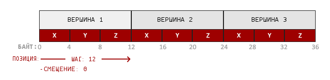
- Position information is stored in a 32 bit (4 byte) floating point value;
- Each position is formed of 3 values;
- There is no separator between sets of 3 values. Such a buffer is called tightly packed ;
- The first value in the transferred data is the beginning of the buffer.
Knowing these features, we can tell OpenGL how it should interpret vertex data. This is done using the glVertexAttribPointer function :
glVertexAttribPointer(0, 3, GL_FLOAT, GL_FALSE, 3 * sizeof(GLfloat), (GLvoid*)0);
glEnableVertexAttribArray(0);
The glVertexAttribPointer function has few parameters, let's quickly go over them:
- Первый аргумент описывает какой аргумент шейдера мы хотим настроить. Мы хотим специфицировать значение аргумента position, позиция которого была указана следующим образом: layout (location = 0).
- Следующий аргумент описывает размер аргумента в шейдере. Поскольку мы использовали vec3 то мы указываем 3.
- Третий аргумент описывает используемый тип данных. Мы указываем GL_FLOAT, поскольку vec в шейдере использует числа с плавающей точкой.
- Четвертый аргумент указывает необходимость нормализовать входные данные. Если мы укажем GL_TRUE, то все данные будут расположены между 0 (-1 для знаковых значений) и 1. Нам нормализация не требуется, поэтому мы оставляем GL_FALSE;
- Пятый аргумент называется шагом и описывает расстояние между наборами данных. Мы также можем указать шаг равный 0 и тогда OpenGL высчитает шаг (работает только с плотно упакованными наборами данных). Как выручить существенную пользу от этого аргумента мы рассмотрим позже.
- Последний параметр имеет тип GLvoid* и поэтому требует такое странное приведение типов. Это смещение начала данных в буфере. У нас буфер не имеет смещения и поэтому мы указываем 0.
Каждый атрибут вершины получает значение из памяти, управляемой VBO, которая в данный момент является привязанной к GL_ARRAY_BUFFER. Соответственно если бы мы вызвали glVertexAttribPointer с другим VBO — то вершинные данные были бы взяты из другого VBO.
After we told OpenGL how it should interpret vertex data, we should enable the attribute using glEnableVertexAttribArray . Thus, we will pass the vertex attribute the position of the argument. After we all set up, we initialized the vertex data in the buffer using VBO, set the vertex and fragment shader and told OpenGL how to connect the vertex shader and the vertex data. Rendering an object in OpenGL will look something like this:
// 0. Копируем массив с вершинами в буфер OpenGL
glBindBuffer(GL_ARRAY_BUFFER, VBO);
glBufferData(GL_ARRAY_BUFFER, sizeof(vertices), vertices, GL_STATIC_DRAW);
// 1. Затем установим указатели на вершинные атрибуты
glVertexAttribPointer(0, 3, GL_FLOAT, GL_FALSE, 3 * sizeof(GLfloat), (GLvoid*)0);
// 2. Используем нашу шейдерную программу
glUseProgram(shaderProgram);
// 3. Теперь уже отрисовываем объект
someOpenGlFunctionThatDrawsOutTriangle();
We must repeat this process every time we draw an object. It doesn't seem to be very difficult, but now imagine that you have more than 5 vertex attributes and something in the region of 100 different objects. And immediately the constant installation of these configurations for each object becomes a wild routine. That would be some way to store all these states and that we would only have to bind to some state for rendering ...
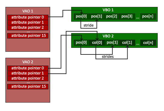
Vertex Array Object
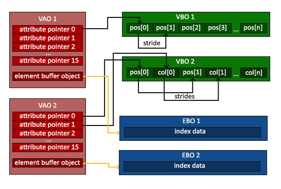
A vertex array object (VAO) can also be bound like a VBO and after that all subsequent calls to the vertex attributes will be stored in the VAO. The advantage of this method is that we need to configure the attributes only once, and the VAO configuration will be used all subsequent times. Also, this method makes it easy to change vertex data and attribute configurations by simply binding different VAOs.
Core OpenGL requires that we use VAO so that OpenGL knows how to work with our input vertices. If we do not specify VAO, OpenGL may refuse to render anything.
VAO stores the following calls:
- Calls glEnableVertexAttribArray or glDisableVertexAttribArray .
- Attribute configuration done through glVertexAttribPointer .
- VBOs associated with vertex attributes using glVertexAttribPointer
The VAO generation process is very similar to VBO generation:
GLuint VAO;
glGenVertexArrays(1, &VAO);
To use VAO, all you have to do is bind the VAO with glBindVertexArray . Now we need to configure / bind the required VBOs and attribute pointers, and at the end untie the VAO for later use. And now, every time we want to draw an object, we simply bind the VAO with the settings we need before rendering the object. It should look something like this:
// ..:: Код инициализации (выполняется единожды (если, конечно, объект не будет часто изменяться)) :: ..
// 1. Привязываем VAO
glBindVertexArray(VAO);
// 2. Копируем наш массив вершин в буфер для OpenGL
glBindBuffer(GL_ARRAY_BUFFER, VBO);
glBufferData(GL_ARRAY_BUFFER, sizeof(vertices), vertices, GL_STATIC_DRAW);
// 3. Устанавливаем указатели на вершинные атрибуты
glVertexAttribPointer(0, 3, GL_FLOAT, GL_FALSE, 3 * sizeof(GLfloat), (GLvoid*)0);
glEnableVertexAttribArray(0);
//4. Отвязываем VAO
glBindVertexArray(0);
[...]
// ..:: Код отрисовки (в игровом цикле) :: ..
// 5. Отрисовываем объект
glUseProgram(shaderProgram);
glBindVertexArray(VAO);
someOpenGLFunctionThatDrawsOurTriangle();
glBindVertexArray(0);
In OpenGL, untying objects is common. At least just to not accidentally ruin the configuration.
That's all! All that we have done over millions of pages has brought us to this point. VAO that stores the vertex attributes and the required VBO. Often, when we have multiple objects for rendering, we first generate and configure VAOs and save them for later use. And when it will be necessary to draw one of our objects, we simply use the saved VAO.
The triangle we have been waiting for
OpenGL provides us with the glDrawArrays function to draw our objects . It uses the active shader and the installed VAO to draw the specified primitives.
glUseProgram(shaderProgram);
glBindVertexArray(VAO);
glDrawArrays(GL_TRIANGLES, 0, 3);
glBindVertexArray(0);
The glDrawArrays function takes the primitive that you want to draw as the first argument to OpenGL. Since we want to draw a triangle and since we don’t want to lie to you, we specify GL_TRIANGLES . The second argument indicates the starting index of the array with the vertices that we want to draw, we just leave 0. The last argument indicates the number of vertices to draw, we need to draw 3 (the length of one triangle is 3 vertices).
Now you can build and run the written code. You will see the following result:
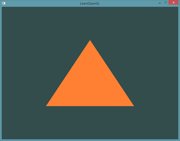
Source code can be found here .
If your result is different then you are probably wrong somewhere. Compare your code with the source code above.
Element Buffer Object
The last thing we talk about today on the topic of vertex rendering is element buffer objects (EBO). In order to explain what it is and how it works, it is better to give an example: suppose that we need to draw not a triangle, but a quadrangle. We can draw a quadrangle using 2 triangles (OpenGL mainly works with triangles).
Note from the translator
As user proydakov noted , this object is also called Index Buffer Object, respectively, IBO.
Accordingly, it will be necessary to declare the following set of vertices:
GLfloat vertices[] = {
    // Первый треугольник
     0.5f,  0.5f, 0.0f,  // Верхний правый угол
     0.5f, -0.5f, 0.0f,  // Нижний правый угол
    -0.5f,  0.5f, 0.0f,  // Верхний левый угол
    // Второй треугольник
     0.5f, -0.5f, 0.0f,  // Нижний правый угол
    -0.5f, -0.5f, 0.0f,  // Нижний левый угол
    -0.5f,  0.5f, 0.0f   // Верхний левый угол
};
As you can see: we indicated the lower right and upper left vertices twice. This is not a very rational use of resources, since we can describe a rectangle with 4 vertices instead of 6. The problem becomes even more significant when we deal with larger models that can have more than 1000 triangles. The most correct solution to this problem is to store only unique vertices, and then separately indicate the order in which we want the rendering to be done. In our case, we would only need to store 4 vertices, and then specify the order in which they need to be drawn. It would be great if OpenGL provided such an opportunity.
Fortunately, EBO is exactly what we need. EBO is a buffer like VBO, but it stores the indexes that OpenGL uses to decide which vertex to draw. This is called indexed drawing and is a solution to the above problem. At the beginning, we will need to specify unique vertices and indices to draw them as triangles:
GLfloat vertices[] = {
     0.5f,  0.5f, 0.0f,  // Верхний правый угол
     0.5f, -0.5f, 0.0f,  // Нижний правый угол
    -0.5f, -0.5f, 0.0f,  // Нижний левый угол
    -0.5f,  0.5f, 0.0f   // Верхний левый угол
};
GLuint indices[] = {  // Помните, что мы начинаем с 0!
    0, 1, 3,   // Первый треугольник
    1, 2, 3    // Второй треугольник
};
As you can see, we only needed 4 vertices instead of 6. Then we need to create an EBO:
GLuint EBO;
glGenBuffers(1, &EBO);
As with VBO, we bind EBO and copy indexes into this buffer via glBufferData . As with VBO, we place calls between binding and decoupling commands ( glBindBuffer (GL_ELEMENT_ARRAY_BUFFER, 0) , only this time the buffer type is GL_ELEMENT_ARRAY_BUFFER .
glBindBuffer(GL_ELEMENT_ARRAY_BUFFER, EBO);
glBufferData(GL_ELEMENT_ARRAY_BUFFER, sizeof(indices), indices, GL_STATIC_DRAW);
Notice that we are passing GL_ELEMENT_ARRAY_BUFFER as the target buffer now. The last thing that remains for us to do is to replace the call to glDrawArrays with the call to glDrawElements in order to indicate that we want to draw triangles from the index buffer. When glDrawElements is used , rendering is performed from the currently bound EBO:
glBindBuffer(GL_ELEMENT_ARRAY_BUFFER, EBO);
glDrawElements(GL_TRIANGLES, 6, GL_UNSIGNED_INT, 0);
The first argument describes the primitive we want to render , just like glDrawArrays . The second argument is the number of elements we want to render. We specified 6 indices, so we pass 6 vertices to the function. The third argument is the index data type, in our case, it is GL_UNSIGNED_INT . The last argument allows us to set the offset in EBO (or pass the array with indexes, but they don’t do this when using EBO), so we just specify 0.
The glDrawElements function takes the indices from the current EB_ bound GL_ELEMENT_ARRAY_BUFFER. This means that if we have to attach different EBOs each time. But VAO knows how to store EBO.
VAO stores calls to glBindBuffer if the target is GL_ELEMENT_ARRAY_BUFFER. It also means that it stores untie calls, too, so make sure you don't untie your EBO before untying the VAO, otherwise you won't have an attached EBO at all.
As a result, you get something like this code:
// ..:: Код инициализации :: ..
// 1. Привязываем VAO
glBindVertexArray(VAO);
    // 2. Копируем наши вершины в буфер для OpenGL
    glBindBuffer(GL_ARRAY_BUFFER, VBO);
    glBufferData(GL_ARRAY_BUFFER, sizeof(vertices), vertices, GL_STATIC_DRAW);
    // 3. Копируем наши индексы в в буфер для OpenGL
    glBindBuffer(GL_ELEMENT_ARRAY_BUFFER, EBO);
    glBufferData(GL_ELEMENT_ARRAY_BUFFER, sizeof(indices), indices, GL_STATIC_DRAW);
    // 3. Устанавливаем указатели на вершинные атрибуты
    glVertexAttribPointer(0, 3, GL_FLOAT, GL_FALSE, 3 * sizeof(GLfloat), (GLvoid*)0);
    glEnableVertexAttribArray(0);
// 4. Отвязываем VAO (НЕ EBO)
glBindVertexArray(0);
[...]
// ..:: Код отрисовки (в игровом цикле) :: ..
glUseProgram(shaderProgram);
glBindVertexArray(VAO);
glDrawElements(GL_TRIANGLES, 6, GL_UNSIGNED_INT, 0)
glBindVertexArray(0);
After starting the program should produce the following result. The left image looks exactly as we planned, the right image is a rectangle drawn in wireframe mode. As you can see this quadrangle is built of 2 triangles.
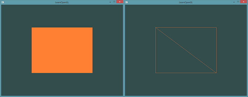
Режим Wireframe
Для того чтобы отрисовать ваши треугольники в этом режиме, укажите OpenGL, как отрисовывать примитивы с помощью glPolygonMode(GL_FRONT_AND_BACK, GL_LINE). Первый аргумент указываем, что мы хотим отрисовывать переднюю и заднюю части всех треугольников, а второй аргумент, что мы хотим отрисовывать только линии. Для того, чтобы вернуться к начальной конфигурации — вызовите glPolygonMode(GL_FRONT_AND_BACK, GL_FILL).
If you have any problems, go over the lesson, maybe you forgot something. You can also check the source code .
If everything worked out for you, then congratulations, you just went through one of the most difficult parts of learning modern OpenGL: finding the first triangle. This part is so complex because it requires a certain set of knowledge before it appears possible to draw the first triangle. Fortunately, we have already gone through this and subsequent lessons should be easier.
Additional Resources
- antongerdelan.net/hellotriangle : Anton Gerdelans draws the first triangle ..
- open.gl/drawing : Alexander Overvoordes draws the first triangle.
- antongerdelan.net/vertexbuffers : a small indentation in VBO.
- learnopengl.com/#!In-Practice/Debugging : Much has been taken from this lesson in this lesson; if you’re stuck somewhere, you can refer to this page. (After the translation of this page, I will make a link to the translation).
Exercises
To consolidate the studied, I will offer several exercises: