State machines in the SimInTech dynamic simulation environment. Part 3. We pass to the C code
- Tutorial
In the first and second parts, an example of creating a control system based on the logic of "finite state machines" was considered and a model of a heater controller was created.
In this part, it will be shown how to generate C code from SimInTech that implements a control program based on the logic of "state machines", and then remove it in MS Visual Studio 2015 together with the object model in SimInTech.
The control algorithm created at the previous stage based on the finite state machine logic in the SimInTech environment can be automatically converted to C code, ready for loading into the controller. I don’t have a controller at hand, so in this example we will simply collect the dll from the generated code. In this part, we will analyze the main steps for preparing the model and generating C code from the SimInTech environment.
Save the project created at the previous stage under the name of Heater.prt.
To create the C code, it is necessary to divide our general model into an object model and a control system model. Since at the first stage we packed the control model into the “Heater Controller” substructure, it is enough for us to take this structure into a separate project.
Create a new project called "Controller_dll" and save it in the same directory. Then copy the “Heater controller” block into it.
To create an external program in SimInTech, you must use special input - output blocks. These blocks “input contact S3” and “output contact S3” are located in the “Data” tab (see Fig. 45 - 46).

Figure 45. Block input contact S3.

Figure 46. Block output pin S3.
Place on the diagram two blocks “input contact S3” and two blocks “output contact S3” and connect to the block “Heater controller”. The type of circuit is shown in Figure 47.

Figure 47. Diagram of the heater controller algorithms in a separate project.
To configure the inputs, go into the properties of the blocks (double-click on the block) and configure the input ports as follows:
“Contact Name” - input: 0 for the first block and input: 1 for the second block
“Contact Type” - Float (see Figure 48 )

Figure 48. Setting the input signal to the program.
To configure the outputs, go into the properties of the blocks and configure the parameters of the output ports as follows:
“Contact name” - out: 0 for the first block and out: 1 for the second block
“Contact type” - Float (see Figure 49)
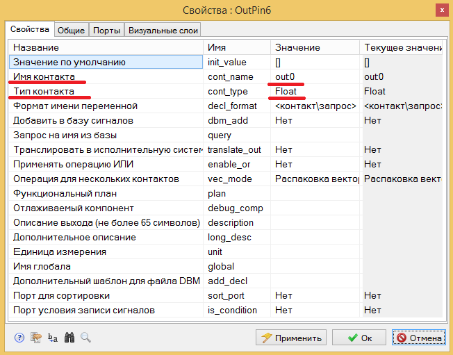
Figure 49. Signal settings exits from the control program.
To configure the name of the program or dynamic library, click the button “Calculation parameters” on the diagram window. In the dialog box that appears, specify the name of the future program. In the "Name (s) of algorithms" parameter, specify controller_dll. (see. Fig. 50)

Figure 50. Setting the program name.
Save the project as dll.prt_controller.
Let's move on to setting up the code generation process. In the main menu of the program, select the item "Code generator". In the dialog box, go to the “Settings” tab and select the template code directory “% codetemplates% VC2015 \” (see Fig. 51)
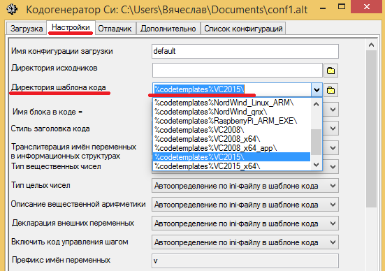
Figure 51. Configuring the code generation template.
To generate code, there is a set of prepared templates configured for various compilers. SimInTech developers offer several options for code generation templates designed for different hardware platforms and OS. Among them - code generation for Windows, Linux, QNX. From the developers site, you can download the MinGW toolkit for creating Windows executables and libraries.
In this example, we will use the template for the Visual Studio 2015 compiler. A free (“communist”) version of this program is sufficient for work. The version of Visual Studio Community 2015 can be downloaded from the official website beta.visualstudio.com/en
The main text of the program is created in the form of pure C code that complies with the ANSI standard. This text is placed in a pre-prepared template for various compilers.
To generate the code in the main menu of the program, select the “Tools” item and the sub-item “Generate program”. When this item is selected, an error message appears at the bottom of the diagram window. Double-clicking on the error line leads to the transition to the submodel in which the error occurred, and a block is selected for which the program code cannot be generated (see Figure 52).

Figure 52. Error message and highlighting the block with the error.
In this case, the error is due to the fact that in the general project we used the global flash_time signal to change the response time of the transition from the state on to the off state and back. After transferring part of the circuit to a new project where there is no such signal, SimInTech shows an error. This error is fixed by creating this signal in a new project. In the SimInTech main menu, select the "Signals" submenu in the "Service" menu (see Figure 53).

Figure 53. Calling up the project signal settings.
Create a new signal (add button at the bottom of the window), set the name flash_time. Set the mode to “Omnidirectional” and set the default value to 5 (see. Fig. 54)
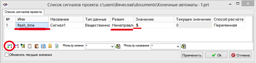
Figure 54. Adding a project signal.
Close the dialog box with the OK button and repeat the code generation process: in the main menu of the program, select the "Generate program" sub-item in the "Tools" item.
If the Visual Studio Community 2015 environment is installed correctly, then the corresponding text will appear in the message box of the circuit (see Figure 55): Figure 55. The message box
about the project.
The first two lines of messages inform about the error - an unregistered code generation module. In an unregistered form, the module allows you to generate code for circuits whose number of blocks does not exceed 200. Our project contains 56 blocks, so the code is generated, despite error messages.
The following messages inform the user about the creation of source code files and indicate where they are located. Unless otherwise specifically indicated in the settings of the code generator, the files are saved in the same directory where we saved the project.
Next, SimInTech reports which code template is used (in which directory it is located).
The last line says that the controller_dll build script is running. If the program Visual Studio 2015 is installed and configured correctly, then opening Explorer, we will see that all the files are in the same folder as the original project. (see. Fig. 56)
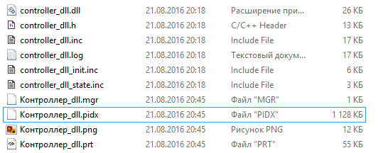
Figure 56. Files created by the code generator and compiler.
Open the source project (we saved it under the name Heater.prt) and save it under the name Heater_loader.prt We will use this project to test the code created by the SimInTech environment.
Remove the “Heater Controller” block and place the “External DLL” block from the “Substructures” tab in its place (see Fig. 57).

Figure 57. Setting up the project for dll testing.
By default, this block does not contain input and output ports. To configure this block, double-click on the block and set the following parameters in the block properties (see Figure 58):

Figure 58. Setting the properties of the “External dll” block
Close the window by clicking the “OK” button, after which ports similar to those of the remote block “Heater Controller” appeared on the diagram of the “External DLL” block. Connect the circuit as shown in Figure 59.

Figure 59. Heater circuit for dll testing.
After that, you can start the project for calculation and see how the code assembled in the dll works.
Earlier, we specified in the properties of the “External DLL” block the name of the project from which the code was generated, and now, during simulation, by double-clicking on the image of the “External DLL” block, the project window will open from which the code was generated and it will be possible to observe code work in dll. (see Fig. 60).
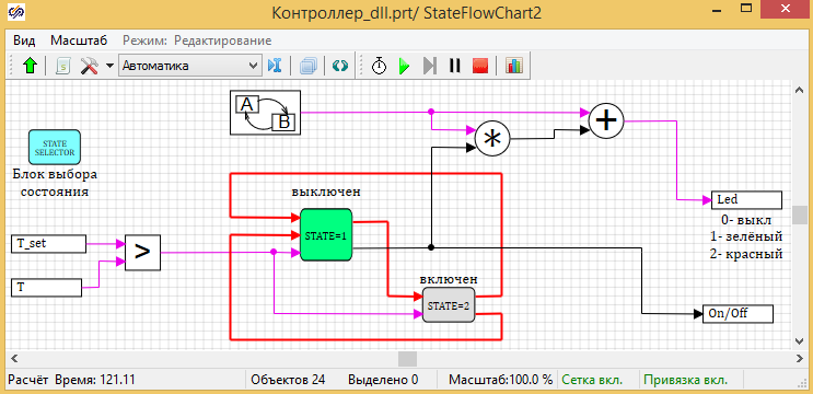
Figure 60. Display on the scheme of work of dll.
The graphs for calculating the model are shown in Figure 61. The graphs show that the temperature drops at the time of shutdown and increases at the time of heating. It is also seen that the mode of operation corresponds to the model of finite state machines created in the first stage. First, for 40 seconds, the heater is turned off and the temperature decreases with a cooling rate, then it is turned on for 20 seconds and the temperature rises with a heating rate. And then the cycle repeats.
But the indicator does not work as planned. The indicator correctly shows the status, but the switching frequency does not change. Obviously, there are problems with the flash_time property of the indicator modeling blocks (see Fig. 61)

Figure 61. The operation graphs of the heater with the controller from dll.
The detected discrepancy between the code and the original model is associated with the features of the code generator. In the SimInTech environment in simulation mode, any property can be set as a variable and calculated using a scripting language, which we did when creating the state machine that controls the indication. During simulation, any change in block properties is possible. The mathematical core of SimInTech takes this into account in the process of sorting blocks and in the calculation process. The operation diagram of the “State Exposure” block in the SimInTech environment is shown in Figure 62.
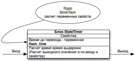
Figure 62. The operation diagram of the “State Exposure” block in the SimInTech environment.
The ability to change parameters on the go, during simulation, significantly increases the flexibility of the system, allows you to select block parameters using SimInTech optimization tools, as well as adjust the controls.
When creating C code, it is necessary to have an unambiguous correspondence between the inputs and outputs of the block with the given parameters. When generating the C code, the ability to change the parameters leads to uncertainty with the formation of the code, in which there should be a clear separation between the input values, the properties of the blocks and the result of the calculation of the block function. To eliminate this uncertainty, all block properties are converted to constants during code generation. The operation diagram of the “State Exposure" block in C code is shown in Figure 63.

Figure 63. The operation diagram of the “State Exposure” block in C code.
To change the properties of a block when working in C code, you must explicitly indicate that the flash_time signal changes during the code operation. In this case, for the code generator, this property turns into a normal input and the uncertainty with the block properties is removed. The operation diagram of the “State Exposure” block will look like that shown in Figure 64.

Figure 64. The operation diagram of the block with a variable exposure time in the C code.
Let's fix our controller taking into account the above features of C code generation in SimInTech.
Open the Controller_dll.prt project, double-click on the “Heater Controller” submodel, then turn it off and remove the “Programming Language” block from the circuit. Place the “Record in the signal list” block from the “Data” tab on the diagram (see Fig. 65)
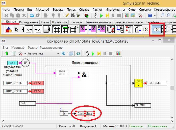
Figure 65. The state diagram is “off” after correction.
In the properties of the "Write to signal list" block, specify the signal name - flash_time. (see. Fig. 66)
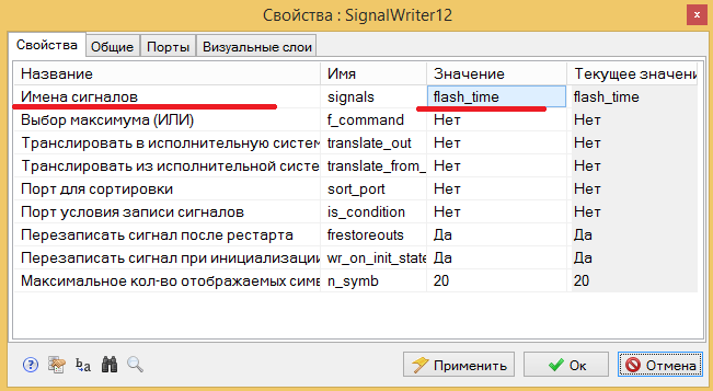
Figure 66. Properties of the “Write to the list of signals” block
Repeat this procedure for the status is on. You can copy the two blocks "Constant" and "Write to the list of signals" and paste in the status block is on. At the input to the unit, apply constant 1 (switching time in heating mode). The status block diagram included should look like Figure 67.
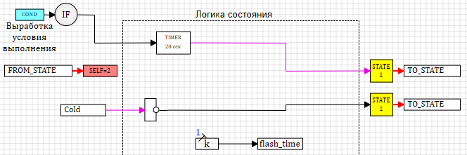
Figure 67. The scheme of work in the on state.
Thus, we explicitly indicated that we want to change the signal from the state circuit when generating the code.
Let's move on to setting up the state machine of indication. Enter the submodel of the display machine, and then - into the off state. Remove the “State exposure” block and replace the “Variable state exposure” block from the “Finite state machines” tab.
Place also the block “Read from the list of signals” from the tab “Data” on the diagram. Set the signal name to flash_time. The circuit should look as shown in Figure 68.
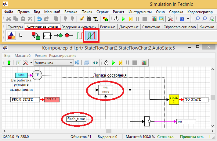
Figure 68. The state circuit is included in the timer operation automaton.
Repeat the same for the off state. The layout should look like the one shown in Figure 69.

Figure 69. The status diagram is turned off.
Thus, we explicitly indicate to the code generator that we want to change the value of the exposure time in the state (indicator blinking interval). Save the project.
Repeat the code generation process. In the main menu of the program, select "Generate program" in the "Tools" item. If you followed the instructions above, then you will have a dll created from C code.
Open the Heater_Loader_Hole project. Run the project for calculation and make sure that now the automatic display is working correctly and changes the frequency of the display depending on the mode. (see. Fig. 70)
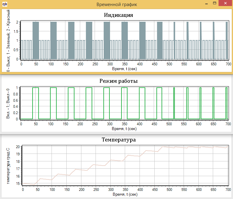
Figure 70. Operation of the heater with the controller from dll.
By default, the SimInTech environment is configured so that the process of creating programs from the circuit is fully automated. The user does not need to edit the text of the program in C. The user receives the program from the circuit, ready to be downloaded to the controller, or in the form of a dll. The previous example shows how to create programs without editing the code.
However, there may be situations where you need to debug C code at the same time and use SimInTech to test this code. Next, we show how to configure Visual Studio 2015 to manually edit C code with testing in the SimInTech environment.
To automate code generation and program creation, SimInTech uses pre-configured templates for different compilers and development environments. In our example, we used the Visual Studio 2015 template, which is located in the folder:
C: \ SimInTech \ bin \ CodeTemplates \ VC2015
This folder contains the command-launch files that provide fully automated library assembly. When generating the code, the files with the code are placed both in the project directory (or another specified by the user during configuration) and in the template directory. The names in the project folder correspond to the program name in the settings of the generation code. The file names in the template folder are fixed, and the files are overwritten when generating different projects in SimInTech.
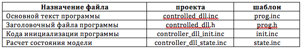
The correspondence between the files in the template pack and the project folder for the heater controller is shown in the following table:
For debugging and manual editing of the source code, you need to transfer the C: \ SimInTech \ bin \ CodeTemplates \ VC2015 \ src folder to the project’s working directory. For our example, do the following:

Figure 72. Configuring the SimInTech environment for dll debugging.
Set a breakpoint to enter the main procedure for executing the RUN_FUNC program and start local debugging by clicking the corresponding button in Visual Studio 2015 (see Figure 73).
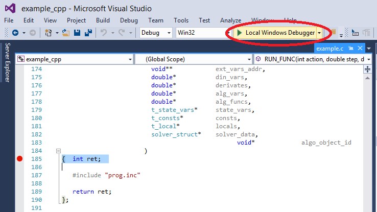
Figure 73. Breakpoint in the main body of the program
If all the settings are correct, then when you start local debugging, SimInTech will be launched and the project Heater_loader_dll.prt will be opened in it.
After starting the simulation of this project in the SimInTech environment, the debugged controller_dll.dll will be called in the first step and control will go to Visual Studio 2015 at the breakpoint.
The created project configuration and working directory settings allow you to manually modify C code in Visual Studio 2015 and perform step-by-step code debugging together with the model in SimInTech. The main text of the program is in the prog.inc file (see Fig. 73).
To configure syntax highlighting of the file with the inc extension in Visual Studio, select “Tools” / “Options ..” in the main menu, in the dialog box under Text Editor / File Extention, add the inc extension.
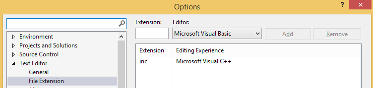
Figure 74. Configuring the file extension.
To search for sections of C code associated with blocks of the calculation scheme, perform the following steps:
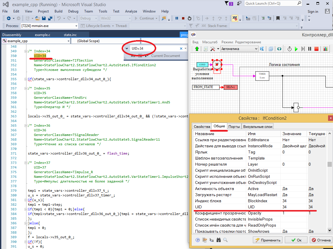
Figure 75. Search for C code by block index in the circuit.
The latest version of SimInTech can be requested here ... The
archive with the project files can be located here ...
In this part, it will be shown how to generate C code from SimInTech that implements a control program based on the logic of "state machines", and then remove it in MS Visual Studio 2015 together with the object model in SimInTech.
The control algorithm created at the previous stage based on the finite state machine logic in the SimInTech environment can be automatically converted to C code, ready for loading into the controller. I don’t have a controller at hand, so in this example we will simply collect the dll from the generated code. In this part, we will analyze the main steps for preparing the model and generating C code from the SimInTech environment.
Save the project created at the previous stage under the name of Heater.prt.
To create the C code, it is necessary to divide our general model into an object model and a control system model. Since at the first stage we packed the control model into the “Heater Controller” substructure, it is enough for us to take this structure into a separate project.
Create a new project called "Controller_dll" and save it in the same directory. Then copy the “Heater controller” block into it.
To create an external program in SimInTech, you must use special input - output blocks. These blocks “input contact S3” and “output contact S3” are located in the “Data” tab (see Fig. 45 - 46).
Figure 45. Block input contact S3.
Figure 46. Block output pin S3.
Place on the diagram two blocks “input contact S3” and two blocks “output contact S3” and connect to the block “Heater controller”. The type of circuit is shown in Figure 47.
Figure 47. Diagram of the heater controller algorithms in a separate project.
To configure the inputs, go into the properties of the blocks (double-click on the block) and configure the input ports as follows:
“Contact Name” - input: 0 for the first block and input: 1 for the second block
“Contact Type” - Float (see Figure 48 )
Figure 48. Setting the input signal to the program.
To configure the outputs, go into the properties of the blocks and configure the parameters of the output ports as follows:
“Contact name” - out: 0 for the first block and out: 1 for the second block
“Contact type” - Float (see Figure 49)
Figure 49. Signal settings exits from the control program.
To configure the name of the program or dynamic library, click the button “Calculation parameters” on the diagram window. In the dialog box that appears, specify the name of the future program. In the "Name (s) of algorithms" parameter, specify controller_dll. (see. Fig. 50)
Figure 50. Setting the program name.
Save the project as dll.prt_controller.
Let's move on to setting up the code generation process. In the main menu of the program, select the item "Code generator". In the dialog box, go to the “Settings” tab and select the template code directory “% codetemplates% VC2015 \” (see Fig. 51)
Figure 51. Configuring the code generation template.
To generate code, there is a set of prepared templates configured for various compilers. SimInTech developers offer several options for code generation templates designed for different hardware platforms and OS. Among them - code generation for Windows, Linux, QNX. From the developers site, you can download the MinGW toolkit for creating Windows executables and libraries.
In this example, we will use the template for the Visual Studio 2015 compiler. A free (“communist”) version of this program is sufficient for work. The version of Visual Studio Community 2015 can be downloaded from the official website beta.visualstudio.com/en
The main text of the program is created in the form of pure C code that complies with the ANSI standard. This text is placed in a pre-prepared template for various compilers.
To generate the code in the main menu of the program, select the “Tools” item and the sub-item “Generate program”. When this item is selected, an error message appears at the bottom of the diagram window. Double-clicking on the error line leads to the transition to the submodel in which the error occurred, and a block is selected for which the program code cannot be generated (see Figure 52).
Figure 52. Error message and highlighting the block with the error.
In this case, the error is due to the fact that in the general project we used the global flash_time signal to change the response time of the transition from the state on to the off state and back. After transferring part of the circuit to a new project where there is no such signal, SimInTech shows an error. This error is fixed by creating this signal in a new project. In the SimInTech main menu, select the "Signals" submenu in the "Service" menu (see Figure 53).
Figure 53. Calling up the project signal settings.
Create a new signal (add button at the bottom of the window), set the name flash_time. Set the mode to “Omnidirectional” and set the default value to 5 (see. Fig. 54)
Figure 54. Adding a project signal.
Close the dialog box with the OK button and repeat the code generation process: in the main menu of the program, select the "Generate program" sub-item in the "Tools" item.
If the Visual Studio Community 2015 environment is installed correctly, then the corresponding text will appear in the message box of the circuit (see Figure 55): Figure 55. The message box
about the project.
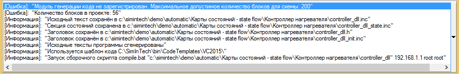
[Error]: “The code generation module is not registered. Maximum allowable number of blocks for the circuit: 200 "
[Error]:" Number of blocks in the project: 56 "
The first two lines of messages inform about the error - an unregistered code generation module. In an unregistered form, the module allows you to generate code for circuits whose number of blocks does not exceed 200. Our project contains 56 blocks, so the code is generated, despite error messages.
[Information]: "The source text is saved in c: \ simintech \ demo \ automatic \ State maps - state flow \ heater controller \ controller_dll.inc"
[Information]: "The state section is saved in c: \ simintech \ demo \ automatic \ Maps state flow - state flow \ Heater controller \ controller_dll_state.inc "
[Information]:" The title is saved in c: \ simintech \ demo \ automatic \ State maps - state flow \ Heater controller \ controller_dll.h "
[Information]:" The title is saved in c: \ simintech \ demo \ automatic \ State maps - state flow \ Heater controller \ controller_dll_init.inc "
[Information]:" The source code of the program is generated "
The following messages inform the user about the creation of source code files and indicate where they are located. Unless otherwise specifically indicated in the settings of the code generator, the files are saved in the same directory where we saved the project.
[Information]: "The code template is used C: \ SimInTech \ bin \ CodeTemplates \ VC2015 \"
[Information]: "Run the compile.bat assembly script„ c: \ simintech \ demo \ automatic \ State maps - state flow \ Heater controller \ controller_dll “192.168.1.1 root root”
Next, SimInTech reports which code template is used (in which directory it is located).
The last line says that the controller_dll build script is running. If the program Visual Studio 2015 is installed and configured correctly, then opening Explorer, we will see that all the files are in the same folder as the original project. (see. Fig. 56)
Figure 56. Files created by the code generator and compiler.
Call created dll from project
Open the source project (we saved it under the name Heater.prt) and save it under the name Heater_loader.prt We will use this project to test the code created by the SimInTech environment.
Remove the “Heater Controller” block and place the “External DLL” block from the “Substructures” tab in its place (see Fig. 57).
Figure 57. Setting up the project for dll testing.
By default, this block does not contain input and output ports. To configure this block, double-click on the block and set the following parameters in the block properties (see Figure 58):
- Number of ports - 2 (Number of input ports).
- An array of output dimensions is [1,1] (For output ports, you need to specify the dimensions of each, we have two ports with 1 signal in the model).
- The names of the loaded DLLs are controller_dll.dll - the name of the file that we specified when generating the code (see Fig. 50).
- The names of the project files for debugging - Controller_dll.prt - the name of the project file under which we saved the scheme for generating the dll.
Figure 58. Setting the properties of the “External dll” block
Close the window by clicking the “OK” button, after which ports similar to those of the remote block “Heater Controller” appeared on the diagram of the “External DLL” block. Connect the circuit as shown in Figure 59.
Figure 59. Heater circuit for dll testing.
After that, you can start the project for calculation and see how the code assembled in the dll works.
Earlier, we specified in the properties of the “External DLL” block the name of the project from which the code was generated, and now, during simulation, by double-clicking on the image of the “External DLL” block, the project window will open from which the code was generated and it will be possible to observe code work in dll. (see Fig. 60).
Figure 60. Display on the scheme of work of dll.
The graphs for calculating the model are shown in Figure 61. The graphs show that the temperature drops at the time of shutdown and increases at the time of heating. It is also seen that the mode of operation corresponds to the model of finite state machines created in the first stage. First, for 40 seconds, the heater is turned off and the temperature decreases with a cooling rate, then it is turned on for 20 seconds and the temperature rises with a heating rate. And then the cycle repeats.
But the indicator does not work as planned. The indicator correctly shows the status, but the switching frequency does not change. Obviously, there are problems with the flash_time property of the indicator modeling blocks (see Fig. 61)
Figure 61. The operation graphs of the heater with the controller from dll.
Features of C code generation in SimInTech
The detected discrepancy between the code and the original model is associated with the features of the code generator. In the SimInTech environment in simulation mode, any property can be set as a variable and calculated using a scripting language, which we did when creating the state machine that controls the indication. During simulation, any change in block properties is possible. The mathematical core of SimInTech takes this into account in the process of sorting blocks and in the calculation process. The operation diagram of the “State Exposure” block in the SimInTech environment is shown in Figure 62.
Figure 62. The operation diagram of the “State Exposure” block in the SimInTech environment.
The ability to change parameters on the go, during simulation, significantly increases the flexibility of the system, allows you to select block parameters using SimInTech optimization tools, as well as adjust the controls.
When creating C code, it is necessary to have an unambiguous correspondence between the inputs and outputs of the block with the given parameters. When generating the C code, the ability to change the parameters leads to uncertainty with the formation of the code, in which there should be a clear separation between the input values, the properties of the blocks and the result of the calculation of the block function. To eliminate this uncertainty, all block properties are converted to constants during code generation. The operation diagram of the “State Exposure" block in C code is shown in Figure 63.
Figure 63. The operation diagram of the “State Exposure” block in C code.
To change the properties of a block when working in C code, you must explicitly indicate that the flash_time signal changes during the code operation. In this case, for the code generator, this property turns into a normal input and the uncertainty with the block properties is removed. The operation diagram of the “State Exposure” block will look like that shown in Figure 64.
Figure 64. The operation diagram of the block with a variable exposure time in the C code.
Let's fix our controller taking into account the above features of C code generation in SimInTech.
Open the Controller_dll.prt project, double-click on the “Heater Controller” submodel, then turn it off and remove the “Programming Language” block from the circuit. Place the “Record in the signal list” block from the “Data” tab on the diagram (see Fig. 65)
Figure 65. The state diagram is “off” after correction.
In the properties of the "Write to signal list" block, specify the signal name - flash_time. (see. Fig. 66)
Figure 66. Properties of the “Write to the list of signals” block
Repeat this procedure for the status is on. You can copy the two blocks "Constant" and "Write to the list of signals" and paste in the status block is on. At the input to the unit, apply constant 1 (switching time in heating mode). The status block diagram included should look like Figure 67.
Figure 67. The scheme of work in the on state.
Thus, we explicitly indicated that we want to change the signal from the state circuit when generating the code.
Let's move on to setting up the state machine of indication. Enter the submodel of the display machine, and then - into the off state. Remove the “State exposure” block and replace the “Variable state exposure” block from the “Finite state machines” tab.
Place also the block “Read from the list of signals” from the tab “Data” on the diagram. Set the signal name to flash_time. The circuit should look as shown in Figure 68.
Figure 68. The state circuit is included in the timer operation automaton.
Repeat the same for the off state. The layout should look like the one shown in Figure 69.
Figure 69. The status diagram is turned off.
Thus, we explicitly indicate to the code generator that we want to change the value of the exposure time in the state (indicator blinking interval). Save the project.
Repeat the code generation process. In the main menu of the program, select "Generate program" in the "Tools" item. If you followed the instructions above, then you will have a dll created from C code.
Open the Heater_Loader_Hole project. Run the project for calculation and make sure that now the automatic display is working correctly and changes the frequency of the display depending on the mode. (see. Fig. 70)
Figure 70. Operation of the heater with the controller from dll.
Collaborative debugging in Visual Studio 2015 and SimInTech
By default, the SimInTech environment is configured so that the process of creating programs from the circuit is fully automated. The user does not need to edit the text of the program in C. The user receives the program from the circuit, ready to be downloaded to the controller, or in the form of a dll. The previous example shows how to create programs without editing the code.
However, there may be situations where you need to debug C code at the same time and use SimInTech to test this code. Next, we show how to configure Visual Studio 2015 to manually edit C code with testing in the SimInTech environment.
To automate code generation and program creation, SimInTech uses pre-configured templates for different compilers and development environments. In our example, we used the Visual Studio 2015 template, which is located in the folder:
C: \ SimInTech \ bin \ CodeTemplates \ VC2015
This folder contains the command-launch files that provide fully automated library assembly. When generating the code, the files with the code are placed both in the project directory (or another specified by the user during configuration) and in the template directory. The names in the project folder correspond to the program name in the settings of the generation code. The file names in the template folder are fixed, and the files are overwritten when generating different projects in SimInTech.
The correspondence between the files in the template pack and the project folder for the heater controller is shown in the following table:
For debugging and manual editing of the source code, you need to transfer the C: \ SimInTech \ bin \ CodeTemplates \ VC2015 \ src folder to the project’s working directory. For our example, do the following:
- Copy C: \ SimInTech \ bin \ CodeTemplates \ VC2015 \ src to the folder in which the Heater Controller project is located (I have C: \ SimInTech \ Demo \ Heater Controller).
- Open the Visual Studio 2015 project file example_cpp.vcxproj located in the C: \ SimInTech \ Demo \ Heater Controller \ src directory in Visual Studio.
- In the project settings, specify the path to the working directories. To do this: in the “Solution Explorer” window, select the example_cpp file and click the “Properties” button. In the settings dialog box, select as “Output Directory” the working directory where the project with the dll call is located. (In our example, the working directory is one level above the directory with the source files). The name of the created dll “Target Name” is controller_dll, the extension of the created file is dll. (see. Fig. 71)
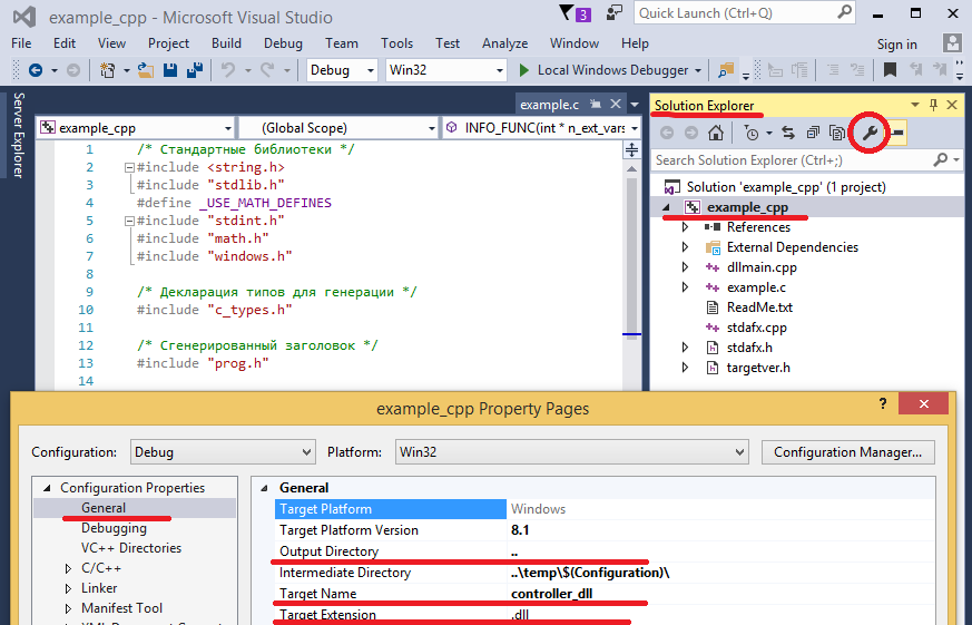
Figure 71. Setting up the debugging working directories - Go to the Debugging section and configure the call to the SimInTech environment:
- “Command” - C: \ SimInTech \ bin \ mmain.exe - the name of the program executable file.
- “Command Arguments” - “C: \ SimInTech \ Demo \ Heater Controller \ Heater_loader_dll.prt” is the name of the project with a call to the debugged dll.
- “Working Directory” - C: \ SimInTech \ Demo \ Heater Controller \ working directory in which we have the project and debug dll (see Fig. 72)
Figure 72. Configuring the SimInTech environment for dll debugging.
Set a breakpoint to enter the main procedure for executing the RUN_FUNC program and start local debugging by clicking the corresponding button in Visual Studio 2015 (see Figure 73).
Figure 73. Breakpoint in the main body of the program
If all the settings are correct, then when you start local debugging, SimInTech will be launched and the project Heater_loader_dll.prt will be opened in it.
After starting the simulation of this project in the SimInTech environment, the debugged controller_dll.dll will be called in the first step and control will go to Visual Studio 2015 at the breakpoint.
The created project configuration and working directory settings allow you to manually modify C code in Visual Studio 2015 and perform step-by-step code debugging together with the model in SimInTech. The main text of the program is in the prog.inc file (see Fig. 73).
To configure syntax highlighting of the file with the inc extension in Visual Studio, select “Tools” / “Options ..” in the main menu, in the dialog box under Text Editor / File Extention, add the inc extension.
Figure 74. Configuring the file extension.
To search for sections of C code associated with blocks of the calculation scheme, perform the following steps:
- Select the block in the diagram.
- Call the window for editing block properties (double click).
- On the General tab, find the unique identifier (UID) value.
- In the Visual Studio window, the search will find the text UID = ”N”, where N is the number of the unique identifier of the block. (See Fig. 75)
Figure 75. Search for C code by block index in the circuit.
The latest version of SimInTech can be requested here ... The
archive with the project files can be located here ...