OpenSceneGraph: Scene Geometry Basics
- Tutorial

Introduction
OpenGL, which is the backend for OpenSceneGraph, uses geometric primitives (such as points, lines, triangles, and polygonal faces) to build all objects in the three-dimensional world.
These primitives are specified by their vertices, which include vertex coordinates, normal components, color data, and texture coordinates. This data is stored in special arrays. Primitives can be formed, for example, by specifying a list of vertex indices for objects describing them. This method is called the vertex array method; it eliminates the storage of redundant vertices in memory and has good speed.
In addition, OpenGL can use the mechanism of so-called display lists.when primitives once prepared in video memory can be reused, which significantly speeds up the display of static objects.
By default, OSG uses the vertex array method and the display list method to render the geometry. However, the rendering strategy may be changed, depending on how the geometry data is presented. In this article we will look at the basic techniques for working with geometry in OSG.
1. Geode and Drawable Classes
The osg :: Geode class is a terminal, so-called "leaf" node of the scene tree. It cannot have child nodes, but it contains all the necessary information for rendering geometry. His name - Geode is an abbreviation for the words geometry node.
Geometric data to be processed by the engine are remembered in a set of objects of the osg :: Drawable class, managed by the osg :: Geode class. The osg :: Drawable class is a purely virtual class. It inherits a number of subclasses, which are three-dimensional models, images and text that are processed by the OpenGL pipeline. A drawable in OSG refers to all elements that can be drawn by the engine.
The osg :: Geode class provides a number of methods for attaching and detaching drawables:
- Public method addDrawable () - passes a pointer to a drawable element to an instance of the class osg :: Geode. All these elements are controlled by smart pointers osg :: ref_ptr <>.
- The public method removeDrawable () and removeDrawables () removes the object from osg :: Geode and reduces the reference count to it. The removeDrawable () method takes as its only parameter a pointer to the element of interest, and the removeDrawables () method takes two parameters: the initial index and the number of elements to be removed from the array of osg :: Geode objects.
- The getDrawable () method returns a pointer to an element at the index passed as a parameter.
- The getNumDrawables () method returns the total number of elements attached to osg :: Geode. For example, to remove all elements from osg :: Geode, you can use such code
geode->removeDrawables(0, geode->getNumDrawables());
2. Drawing the simplest shapes
OSG provides the osg :: ShapeDrawable class, which is derived from the osg :: Drawable class, and is intended to create the simplest three-dimensional primitives. This class includes an osg :: Shape object that stores information about a specific geometry and more parameters. Primitives are generated using the setShape () method, for example
shapeDrawable->setShape(new osg::Box(osg::Vec3(1.0f, 0.0f, 0.0f), 10.0f, 10.0f, 5.0f));
creates a rectangular parallelepiped with a geometric center at the point (1.0, 0.0, 0.0) with a width and height of 10 and a depth of 5 units. The class osg :: Vec3 defines a vector in three-dimensional space (in addition, the classes osg :: Vec2 and osg :: Vec4 describe the vectors of the corresponding dimension are presented).
The most popular primitives are represented in OSG by the classes osg :: Box, osg :: Capsule, osg :: Cone, osg :: Cylinder and osg :: Sphere.
Consider an example of this mechanism.
main.h
#ifndef MAIN_H#define MAIN_H#include<osg/ShapeDrawable>#include<osg/Geode>#include<osgViewer/Viewer>#endif// MAIN_Hmain.cpp
#include"main.h"intmain(int argc, char *argv[]){
    (void) argc;
    (void) argv;
    osg::ref_ptr<osg::ShapeDrawable> shape1 = new osg::ShapeDrawable;
    shape1->setShape(new osg::Box(osg::Vec3(-3.0f, 0.0f, 0.0f), 2.0f, 2.0f, 1.0f));
    osg::ref_ptr<osg::ShapeDrawable> shape2 = new osg::ShapeDrawable;
    shape2->setShape(new osg::Cone(osg::Vec3(0.0f, 0.0f, 0.0f), 1.0f, 1.0f));
    shape2->setColor(osg::Vec4(0.0f, 1.0f, 0.0f, 1.0f));
    osg::ref_ptr<osg::ShapeDrawable> shape3 = new osg::ShapeDrawable;
    shape3->setShape(new osg::Sphere(osg::Vec3(3.0f, 0.0f, 0.0f), 1.0f));
    shape3->setColor(osg::Vec4(0.0f, 0.0f, 1.0f, 1.0f));
    osg::ref_ptr<osg::Geode> root = new osg::Geode;
    root->addDrawable(shape1.get());
    root->addDrawable(shape2.get());
    root->addDrawable(shape3.get());
    osgViewer::Viewer viewer;
    viewer.setSceneData(root.get());
    return viewer.run();
}
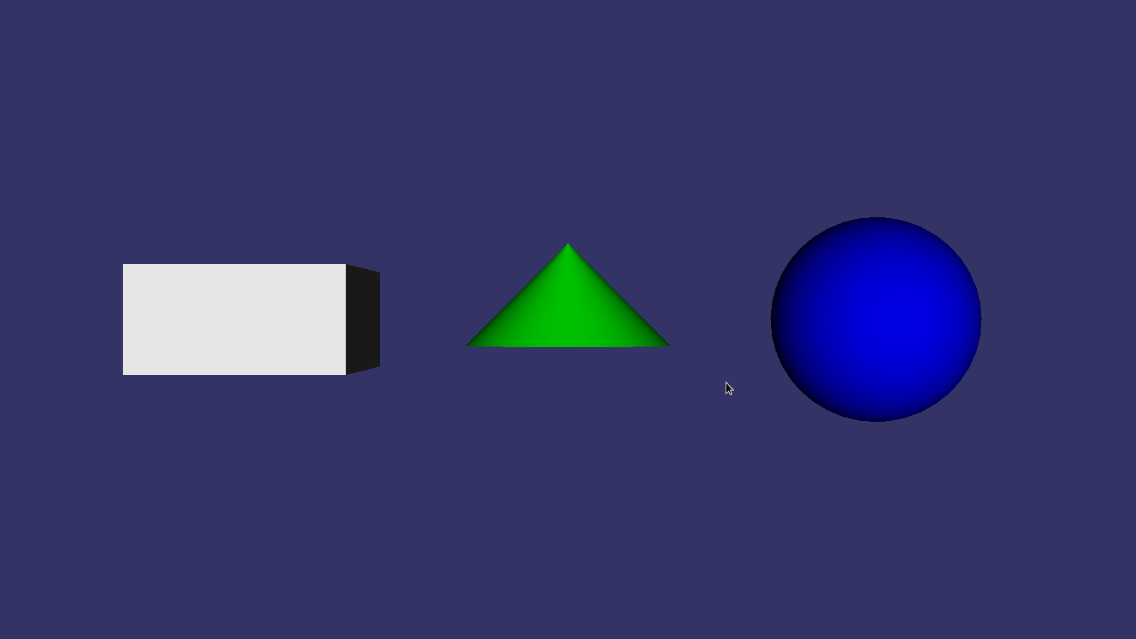
This example does not need any comments: the program creates three simple shapes, after compiling and running, we will see this result.
The mechanism shown in the example is simple and straightforward, but it is not the most effective way to create geometry and can be used exclusively for tests. To create geometry in high-performance OSG-based applications, the class osg :: Geometry is used.
3. Geometry data storage: classes osg :: Array and osg :: Geometry
The osg :: Array class is a basic abstract class, from which several descendants are inherited, intended for storing data passed to the OpenGL functions. Working with this class is similar to working with std :: vector from the standard C ++ library. The following code illustrates adding a vector to an array of vertices using the push_back () method
vertices->push_back(osg::Vec3(1.0f, 0.0f, 0.0f));
OSG arrays are allocated in a heap and controlled by smart pointers. However, this does not apply to array elements, such as osg :: Vec3 or osg :: Vec2, which can also be created on the stack.
The osg :: Geometry class is a wrapper around OpenGL functions that work with arrays of vertices. It is derived from the class osg :: Drawable and can easily be added to the list of objects osg :: Geode. This class takes the above arrays as input and uses them to generate geometry using OpenGL.
4. Vertices and their attributes
Vertex is an atomic unit of primitives of geometry. It has a number of attributes that describe a point of two- or three-dimensional space. Attributes include: position, color, normal vector, texture coordinates, fog coordinates, and so on. A vertex must always have a position in space, as for other attributes, they may optionally be present. OpenGL supports 16 basic vertex attributes and can use different arrays to store them. All attribute arrays are supported by the osg :: Geometry class and can be set by methods of the type set * Array ().
Vertex Attributes in OpenSceneGraph
| Attribute | Data type | Osg method :: Geometry | Equivalent OpenGL call |
|---|---|---|---|
| Position | 3-vector | setVertexArray () | glVertexPointer () |
| Normal | 3-vector | setNormalArray () | glNormalPointer () |
| Colour | 4-vector | setColorArray () | glColorPointer () |
| Secondary color | 4-vector | setSecondaryColorArray () | glSecondaryColorPointerEXT () |
| Fog Coordinates | float | setFogCoordArray () | glFogCoordPointerEXT () |
| Texture coordinates | 2- or 3-vector | setTexCoordArray () | glTexCoordPointer () |
| Other attributes | User defined | setVertexArribArray () | glVertexAttribPointerARB () |
In principle, it is necessary to set your attributes for each of the vertices, which leads to the formation of several arrays of attributes of the same size - otherwise the mismatch of the sizes of the arrays can lead to undefined behavior of the engine. OSG supports various methods of linking vertex attributes, for example
geom->setColorBinding(osg::Geometry::BIND_PER_VERTEX);
means that each vertex and each vertex color are in one-to-one correspondence with each other. However, if you look at this code
geom->setColorBinding(osg::Geometry::BIND_OVERALL);
then he applies one color to the whole geometry. Similarly, relationships between other attributes can be configured by calling the setNormalBinding (), setSecondaryColorBinding (), setFogCoordBinding () methods and setVertexAttribBinding ().
5. Sets of primitive geometry
The next step after determining the arrays of the vertex attributes is a description of how the vertex data will be rendered. The virtual class osg :: PrimitiveSet is used to control the geometric primitives generated by the render from a set of vertices. The osg :: Geometry class provides several methods for working with sets of geometry primitives:
- addPrimitiveSet () - passes a pointer to a set of primitives to the object osg :: Geometry.
- removePrimitiveSet () - remove a set of primitives. As parameters it takes the initial index of the sets and the number of sets to be deleted.
- getPrimitiveSet () - returns a set of primitives by the index passed as a parameter.
- getNumPrimitiveSets () - returns the total number of primitive sets associated with this geometry.
The osg :: PrimitiveSet class is abstract and not instantiated, but several derived classes inherit from it, encapsulating sets of primitives that OpenGL operates on, such as osg :: DrawArrays and osg :: DrawElementsUInt.
The osg :: DrawArrays class uses several consecutive elements of an array of vertices to construct a geometric primitive. It can be created and attached to the geometry by calling the method.
geom->addPrimitiveSet(new osg::DrawArrays(mode, first, count));
The first parameter specifies the type of the primitive mode, similar to the corresponding OpenGL primitive types: GL_POINTS, GL_LINE_STRIP, GL_LINE_LOOP, GL_LINES , GL_TRIANGLE_STRIP, GL_TRIANGLE_FAN, GL_TRIANGLES, GL_QUAD_STRIP, GL_QUADS and GL_POLYGON.
The first and second parameters specify the first index in the array of vertices and the number of vertices from which the geometry should be generated. Moreover, OSG does not check whether the specified number of vertices is enough to build the geometry specified by the mode, which can lead to application crash!
6. Example - draw a colored square.
We implement all of the above as a simple example.
Full quad source code
main.h
main.cpp
#ifndef MAIN_H#define MAIN_H#include<osg/Geometry>#include<osg/Geode>#include<osgViewer/Viewer>#endif// MAIN_Hmain.cpp
#include"main.h"intmain(int argc, char *argv[]){
    osg::ref_ptr<osg::Vec3Array> vertices = new osg::Vec3Array;
    vertices->push_back(osg::Vec3(0.0f, 0.0f, 0.0f));
    vertices->push_back(osg::Vec3(1.0f, 0.0f, 0.0f));
    vertices->push_back(osg::Vec3(1.0f, 0.0f, 1.0f));
    vertices->push_back(osg::Vec3(0.0f, 0.0f, 1.0f));
    osg::ref_ptr<osg::Vec3Array> normals = new osg::Vec3Array;
    normals->push_back(osg::Vec3(0.0f, -1.0f, 0.0f));
    osg::ref_ptr<osg::Vec4Array> colors = new osg::Vec4Array;
    colors->push_back(osg::Vec4(1.0f, 0.0f, 0.0f, 1.0f));
    colors->push_back(osg::Vec4(0.0f, 1.0f, 0.0f, 1.0f));
    colors->push_back(osg::Vec4(0.0f, 0.0f, 1.0f, 1.0f));
    colors->push_back(osg::Vec4(1.0f, 1.0f, 1.0f, 1.0f));
    osg::ref_ptr<osg::Geometry> quad = new osg::Geometry;
    quad->setVertexArray(vertices.get());
    quad->setNormalArray(normals.get());
    quad->setNormalBinding(osg::Geometry::BIND_OVERALL);
    quad->setColorArray(colors.get());
    quad->setColorBinding(osg::Geometry::BIND_PER_VERTEX);
    quad->addPrimitiveSet(new osg::DrawArrays(GL_QUADS, 0, 4));
    osg::ref_ptr<osg::Geode> root = new osg::Geode;
    root->addDrawable(quad.get());
    osgViewer::Viewer viewer;
    viewer.setSceneData(root.get());
    return viewer.run();
}
After compilation and execution we will get a result similar to this.

This example needs clarification. So, first of all we create an array of vertices of the square in which their coordinates are stored.
osg::ref_ptr<osg::Vec3Array> vertices = new osg::Vec3Array;
vertices->push_back(osg::Vec3(0.0f, 0.0f, 0.0f));
vertices->push_back(osg::Vec3(1.0f, 0.0f, 0.0f));
vertices->push_back(osg::Vec3(1.0f, 0.0f, 1.0f));
vertices->push_back(osg::Vec3(0.0f, 0.0f, 1.0f));
Next, set the array of normals. In our simple case, we do not need to create a normal for each vertex; it suffices to describe one unit vector that is perpendicular to the plane of the square.
osg::ref_ptr<osg::Vec3Array> normals = new osg::Vec3Array;
normals->push_back(osg::Vec3(0.0f, -1.0f, 0.0f));
Set a color for each of the vertices.
osg::ref_ptr<osg::Vec4Array> colors = new osg::Vec4Array;
colors->push_back(osg::Vec4(1.0f, 0.0f, 0.0f, 1.0f));
colors->push_back(osg::Vec4(0.0f, 1.0f, 0.0f, 1.0f));
colors->push_back(osg::Vec4(0.0f, 0.0f, 1.0f, 1.0f));
colors->push_back(osg::Vec4(1.0f, 1.0f, 1.0f, 1.0f));
Now create a geometry object, where the description of our square will be stored, which will be rendered. Pass an array of vertices to this geometry.
osg::ref_ptr<osg::Geometry> quad = new osg::Geometry;
quad->setVertexArray(vertices.get());
Transmitting an array of normals, we inform the engine that a single normal will be used for all vertices, indicating the method of linking ("binding") the normals BIND_OVAERALL
quad->setNormalArray(normals.get());
quad->setNormalBinding(osg::Geometry::BIND_OVERALL);
By passing the colors of the vertices, on the contrary, we indicate that each vertex will have its own color
quad->setColorArray(colors.get());
quad->setColorBinding(osg::Geometry::BIND_PER_VERTEX);
Now we create a set of primitives for geometry. We indicate that square (GL_QUADS) faces should be generated from the array of vertices, taking the vertex with index 0 as the first vertex, and the total number of vertices will be 4
quad->addPrimitiveSet(new osg::DrawArrays(GL_QUADS, 0, 4));
Well, the transfer of geometry and the launch of the render explain, I think you should not
osg::ref_ptr<osg::Geode> root = new osg::Geode;
root->addDrawable(quad.get());
osgViewer::Viewer viewer;
viewer.setSceneData(root.get());
return viewer.run();
The code above is equivalent to the following construct on pure OpenGL.
staticconst GLfloat vertices[][3] = { … };
glEnableClientState( GL_VERTEX_ARRAY );
glVertexPointer( 4, GL_FLOAT, 0, vertices );
glDrawArrays( GL_QUADS, 0, 4 );
7. Indexing vertices in primitives
The osg :: DrawArrays class works well when reading vertex data directly from arrays, without gaps. However, it is not so effective when the same vertex can belong to several faces of an object. Consider the example.

A cube has eight vertices. However, as can be seen from the figure (we are looking at sweeping a cube onto a plane), some vertices belong to more than one face. If we build a cube of 12 triangular faces, then these vertices will be repeated, and instead of an array of 8 vertices, we will get an array of 36 vertices, most of which are in fact the same vertex!
In OSG, there are classes osg :: DrawElementsUInt, osg :: DrawElementsUByte and osg :: DrawElementsUShort, which use arrays of vertex indices as data, designed to solve the described problem. Arrays of indices store the indexes of the vertices of the primitives that describe the faces and other elements of the geometry. When applying these classes to a cube, it is sufficient to store an array of eight vertices, which are associated with faces through arrays of indices.
Classes of the osg :: DrawElements * type are designed in the same way as the standard std :: vector class. This code can be used to add indexes.
osg::ref_ptr<osg::DrawElementsUInt> de = new osg::DrawElementsUInt(GL_TRIANGLES);
de->push_back(0); de->push_back(1); de->push_back(2);
de->push_back(3); de->push_back(0); de->push_back(2);
This code defines the front face of the cube shown in the figure.
Consider another illustrative example - the octahedron. It
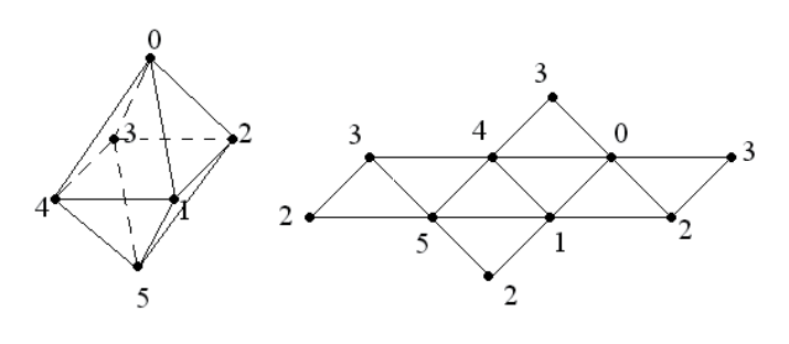
is interesting because it contains only six vertices, but each vertex is already in four triangular faces! We can create an array of 24 vertices to display all eight faces using osg :: DrawArrays. However, we will act differently - we will store vertices in an array of six elements, and generate faces using the class osg :: DrawElementsUInt.
Full source code of the octahedron example
main.h
main.cpp
#ifndef MAIN_H#define MAIN_H#include<osg/Geometry>#include<osg/Geode>#include<osgUtil/SmoothingVisitor>#include<osgViewer/Viewer>#endifmain.cpp
#include"main.h"intmain(int argc, char *argv[]){
    osg::ref_ptr<osg::Vec3Array> vertices = new osg::Vec3Array(6);
    (*vertices)[0].set( 0.0f,  0.0f,  1.0f);
    (*vertices)[1].set(-0.5f, -0.5f,  0.0f);
    (*vertices)[2].set( 0.5f, -0.5f,  0.0f);
    (*vertices)[3].set( 0.5f,  0.5f,  0.0f);
    (*vertices)[4].set(-0.5f,  0.5f,  0.0f);
    (*vertices)[5].set( 0.0f,  0.0f, -1.0f);
    osg::ref_ptr<osg::DrawElementsUInt> indices = new osg::DrawElementsUInt(GL_TRIANGLES, 24);
    (*indices)[ 0] = 0; (*indices)[ 1] = 1; (*indices)[ 2] = 2;
    (*indices)[ 3] = 0; (*indices)[ 4] = 4; (*indices)[ 5] = 1;
    (*indices)[ 6] = 4; (*indices)[ 7] = 5; (*indices)[ 8] = 1;
    (*indices)[ 9] = 4; (*indices)[10] = 3; (*indices)[11] = 5;
    (*indices)[12] = 3; (*indices)[13] = 2; (*indices)[14] = 5;
    (*indices)[15] = 1; (*indices)[16] = 5; (*indices)[17] = 2;
    (*indices)[18] = 3; (*indices)[19] = 0; (*indices)[20] = 2;
    (*indices)[21] = 0; (*indices)[22] = 3; (*indices)[23] = 4;
    osg::ref_ptr<osg::Geometry> geom = new osg::Geometry;
    geom->setVertexArray(vertices.get());
    geom->addPrimitiveSet(indices.get());
    osgUtil::SmoothingVisitor::smooth(*geom);
    osg::ref_ptr<osg::Geode> root = new osg::Geode;
    root->addDrawable(geom.get());
    osgViewer::Viewer viewer;
    viewer.setSceneData(root.get());
    return viewer.run();
}
Let's sort this code in more detail. Of course, first of all, we create an array of six vertices
osg::ref_ptr<osg::Vec3Array> vertices = new osg::Vec3Array(6);
(*vertices)[0].set( 0.0f,  0.0f,  1.0f);
(*vertices)[1].set(-0.5f, -0.5f,  0.0f);
(*vertices)[2].set( 0.5f, -0.5f,  0.0f);
(*vertices)[3].set( 0.5f,  0.5f,  0.0f);
(*vertices)[4].set(-0.5f,  0.5f,  0.0f);
(*vertices)[5].set( 0.0f,  0.0f, -1.0f);
We initialize each vertex directly, addressing the vector of its coordinates using the pointer dereference operation and operator [] operator (we remember that osg :: Array is similar in its std :: vector device).
Now we create faces as a list of vertex indexes.
osg::ref_ptr<osg::DrawElementsUInt> indices = new osg::DrawElementsUInt(GL_TRIANGLES, 24);
(*indices)[ 0] = 0; (*indices)[ 1] = 1; (*indices)[ 2] = 2; // Грань 0
(*indices)[ 3] = 0; (*indices)[ 4] = 4; (*indices)[ 5] = 1; // Грань 1
(*indices)[ 6] = 4; (*indices)[ 7] = 5; (*indices)[ 8] = 1; // Грань 2
(*indices)[ 9] = 4; (*indices)[10] = 3; (*indices)[11] = 5; // Грань 3
(*indices)[12] = 3; (*indices)[13] = 2; (*indices)[14] = 5; // Грань 4
(*indices)[15] = 1; (*indices)[16] = 5; (*indices)[17] = 2; // Грань 5
(*indices)[18] = 3; (*indices)[19] = 0; (*indices)[20] = 2; // Грань 6
(*indices)[21] = 0; (*indices)[22] = 3; (*indices)[23] = 4; // Грань 7
Faces will be triangular, there will be 8 of them, which means the list of indices should contain 24 elements. Face indices go in this array sequentially: for example, face 0 is formed by vertices 0, 1 and 2; face 1 - vertices 0, 4 and 1; face 2 - vertices 4, 5 and 1, and so on. Vertices are listed in the order of counterclockwise, if you look at the front side of the face (see the figure above).
Further steps to create the geometry we performed in the previous examples. The only thing we did not do was the automatic generation of smoothed (averaged) normals, which we perform in this example by calling
osgUtil::SmoothingVisitor::smooth(*geom);
Indeed, if the vertices of the face are given, then it is easy to calculate the normal to it. At the vertices in which several faces converge, a certain average normal is calculated - the normals of converging faces are added up and the resulting sum is normalized again. These operations (and much more!) Can be performed by the engine itself using classes from the osgUtil library. Therefore, in our example, in the * .pro file we will add an indication to the linker to build our program and with this library
octahedron.pro
CONFIG(debug, debug|release) {
    TARGET = $$join(TARGET,,,_d)
		.
		.
		.
    LIBS += -L$$OSG_LIB_DIRECTORY -losgUtild
} else {
		.
		.
		.
    LIBS += -L$$OSG_LIB_DIRECTORY -losgUtil
}
As a result, we get the following result.
To understand how this works, consider the OpenGL pipeline.

The vertex array mechanism reduces the number of OpenGL calls. It stores vertex data in the memory of the application that is used on the client side. The server-side OpenGL pipeline accesses various vertex arrays. As shown in the diagram, OpenGL retrieves data from the vertex buffer on the client side and, in an orderly manner, assembles the primitives. This is how data is processed using the set * Array () methods of the osg :: Geometry class. The osg :: DrawArrays class traverses these arrays directly and displays them.
When using osg :: DrawElements *, the dimension of arrays of vertices is reduced and the number of vertices passed to the pipeline is reduced. An array of indices allows you to create a vertex cache on the server side. OpenGL reads the vertex data from the cache, instead of reading from the vertex buffer on the client side. This significantly increases the overall rendering performance.
8. Polygonal mesh processing techniques
OpenSceneGraph supports various techniques for processing a polygonal mesh of scene geometry objects. These preprocessing methods, such as polygon reduction and tessellation, are often used to create and optimize polygonal models. They have a simple interface, but in the process they do a lot of complex calculations and are not very suitable for execution on the fly.
These techniques include:
- osgUtil :: Simplifier - reducing the number of triangles in geometry. The public method simplify () is used to simplify the geometry of models.
- osgUtil :: SmootingVisitor - calculation of normals. The smooth () method can be used to generate smoothed normals for a model, instead of calculating them independently and explicitly specifying them through an array of normals.
- osgUtil :: TangentSpaceGenerator - generation of tangent basis vectors for model vertices. It is launched by calling the generate () method and stores the result returned by the getTangentArray (), getNormalArray () and getBinormalArray () methods. These results can be used for various vertex attributes when writing shaders on the GLSL.
- osgUtil :: Tesselator - performs tessellation of a polygonal mesh - splitting complex primitives into a sequence of simple (retesselatePolygons () method)
- osgUtil :: TriStripVisitor - converts a geometric surface into a set of strips of triangular faces, which allows rendering with effective memory consumption. The stripify () method converts a set of model primitives into a geometry based on the GL_TRIANGLE_STRIP set.
All methods accept object geometry as a parameter, passed by reference osg :: Geometry &, for example:
osgUtil::TriStripVisitor tsv;
tsv.stripify(*geom);
where geom is an instance of a geometry, described by a smart pointer.
The classes osg :: Simplifier, osg :: SmoothingVisitor and osg :: TriStripVisitor can work directly with the nodes of the scene graph, for example
osgUtil::TriStripVisitor tsv;
node->accept(tsv);
The accept () method processes all the child nodes until the specified operation is applied to all end nodes of this part of the scene tree stored in nodes like osg :: Geode.
Let's try to practice the tessellation technique.
Full tesselator sample code
main.h
main.cpp
#ifndef MAIN_H#define MAIN_H#include<osg/Geometry>#include<osg/Geode>#include<osgUtil/Tessellator>#include<osgViewer/Viewer>#endifmain.cpp
#include"main.h"intmain(int argc, char *argv[]){
	/*
		Создаем фигуру вида
		-----
		|  _|
		| |_
		|    |
		-----
	*/
    osg::ref_ptr<osg::Vec3Array> vertices = new osg::Vec3Array;
    vertices->push_back( osg::Vec3(0.0f, 0.0f, 0.0f) ); // 0
    vertices->push_back( osg::Vec3(2.0f, 0.0f, 0.0f) ); // 1
    vertices->push_back( osg::Vec3(2.0f, 0.0f, 1.0f) ); // 2
    vertices->push_back( osg::Vec3(1.0f, 0.0f, 1.0f) ); // 3
    vertices->push_back( osg::Vec3(1.0f, 0.0f, 2.0f) ); // 4
    vertices->push_back( osg::Vec3(2.0f, 0.0f, 2.0f) ); // 5
    vertices->push_back( osg::Vec3(2.0f, 0.0f, 3.0f) ); // 6
    vertices->push_back( osg::Vec3(0.0f, 0.0f, 3.0f) ); // 7
    osg::ref_ptr<osg::Vec3Array> normals = new osg::Vec3Array;
    normals->push_back( osg::Vec3(0.0f, -1.0f, 0.0f) );
    osg::ref_ptr<osg::Geometry> geom = new osg::Geometry;
    geom->setVertexArray(vertices.get());
    geom->setNormalArray(normals.get());
    geom->setNormalBinding(osg::Geometry::BIND_OVERALL);
    geom->addPrimitiveSet(new osg::DrawArrays(GL_POLYGON, 0, 8));
    osg::ref_ptr<osg::Geode> root = new osg::Geode;
    root->addDrawable(geom.get());
    osgViewer::Viewer viewer;
    viewer.setSceneData(root.get());
    return viewer.run();
}
Based on the spatial position of the vertices in this example, it is clear that we are trying to create a non-convex polygon of eight vertices using the generation of one face of type GL_POLYGON. Building and executing this example shows that the result that we expect does not work — the example is displayed incorrectly.

To fix this problem, the constructed geometry should be tessellated before passing it to the viewer.
osgUtil::Tessellator ts;
ts.retessellatePolygons(*geom);
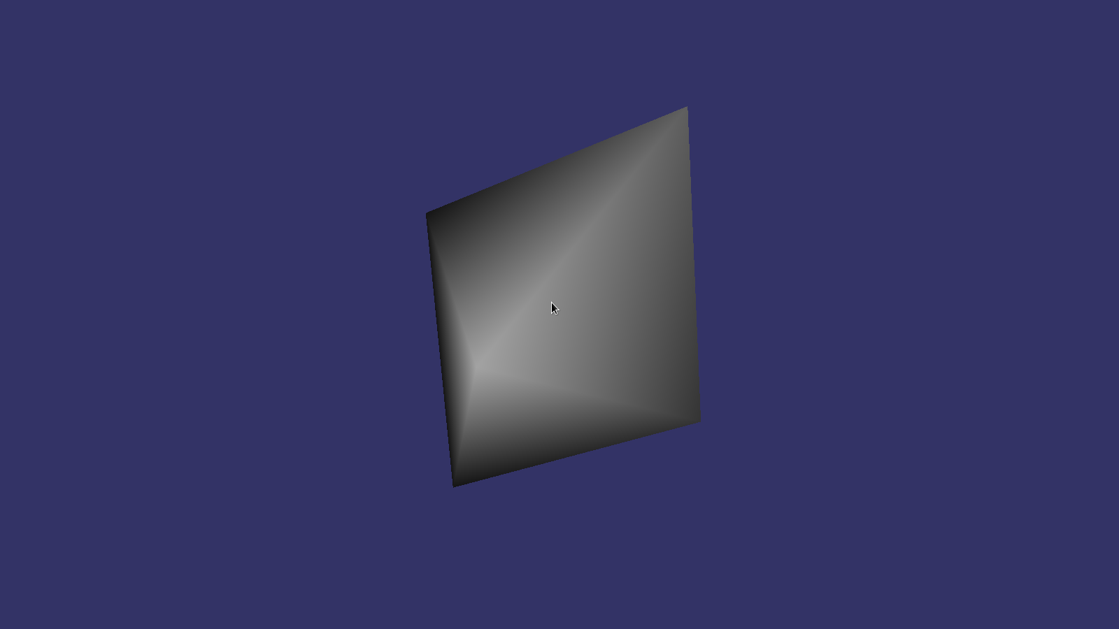
after which we get the correct result.

How does it work? A non-convex polygon, without the use of a correct tessellation, will not be displayed as we expect, since OpenGL, seeking to optimize performance, will consider it as a simple, convex polygon or simply ignore, which may give completely unexpected results.
The class osgUtil :: Tessellator uses algorithms to transform a convex polygon into a series of non-convex - in our case, it transforms the geometry into GL_TRIANGLE_STRIP.
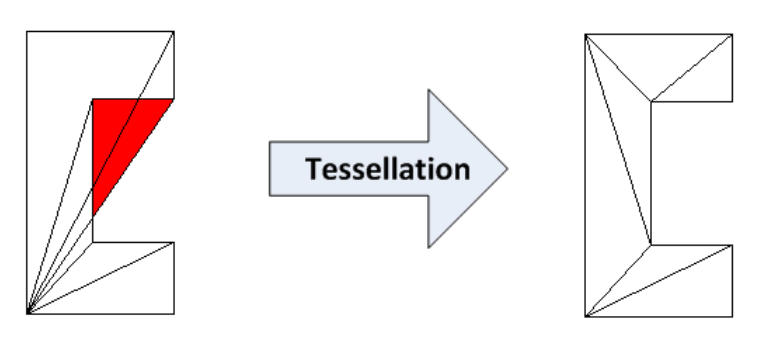
This class can handle hole polygons and self-intersecting polygons. Through the public setWindingType () method, you can define various processing rules, such as GLU_TESS_WINDING_ODD or GLU_TESS_WINDING_NONZERO, which define the inside and outside areas of a complex polygon.
Conclusion
In this article, we got a basic understanding of how the geometry of three-dimensional objects is stored and processed in the OSG engine. Do not think that those simple and not very impressive examples that are considered in the article - the limit of the engine. Simply, these examples can help the developer to understand the mechanics of OpenSceneGraph, and without this understanding it is difficult to imagine the work of more complex things.
This article is based on the translation and processing of the text of the corresponding chapters of the book OpenSceneGraph 3.0. Beginner's Guide . All examples are checked by me personally, and their source is available here . To be continued...