Why "Young Technician" will not be able to build a laser
Greetings to all again. In the comments on my first article about a self-made laser system, they again recalled an article from the magazine Young Technician, which was called “Building a Laser”. It provides a phased description of the assembly of a pulsed laser operating on a liquid solution of an organic dye. The text of the article is available after 2 minutes of googling.
Despite this, neither me nor my colleagues are aware of the precedents for the successful construction of a dye laser, guided by this article. Why is that? What are the hidden pitfalls in dye lasers? How are industrial dye lasers arranged? Let's figure it out.

The dye laser is very attractive for DIY. Since it does not need scarce and hard-to-reach crystals or glasses, or complex glass-blowing work as for the manufacture of active elements of gas lasers. It consumes very little energy and produces bright visible light. Its radiation has a very valuable property - it can be decomposed into the spectrum and highlight the desired color of the beam.
To begin with, it should be noted that the article from UT No. 8 of 1971, which was then re-issued in No. 11 of 1992, is not original. This is an adaptation of an article published in the “The amateur scientist” column of the American journal “Scientific American” in the February 1970 issue. And everything would be fine (maybe!) If this adaptation were not performed with unacceptable reductions and annoying errors. First, let's look at the volume of both articles. The original article occupied 6 pages, adapted at UT - only 3 pages. Pictures are copied practically 1 in 1. The original American article can be downloaded from here, having stolen it from evil copywriters through sci-hub. Or already from the file hosting .
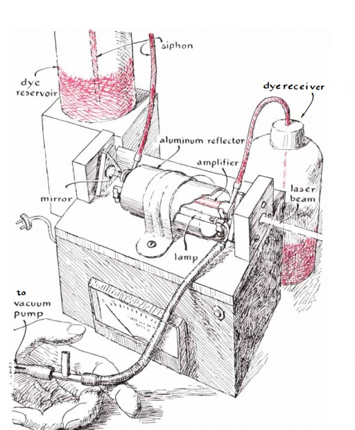
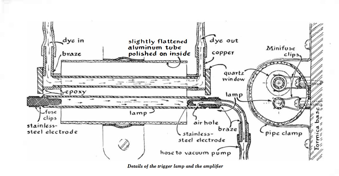
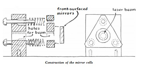
Compare the similarity of the pictures in the original and adapted articles.
Original:
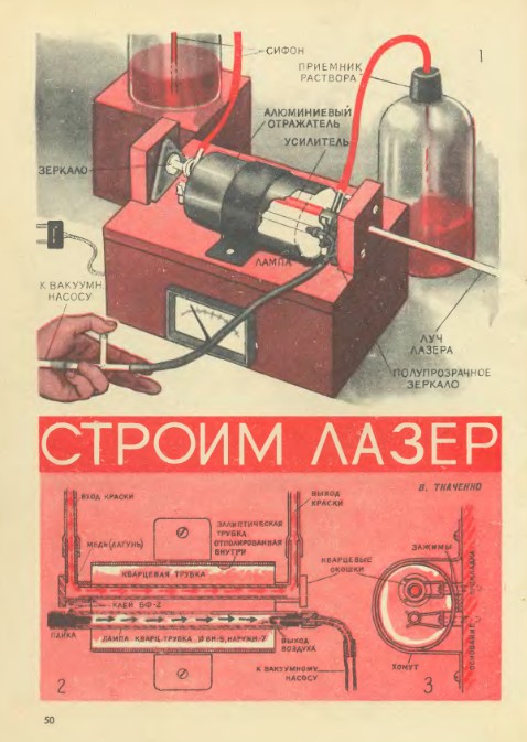
Now let's look at the pictures from UT:
On this, the similarities in the pictures end and the differences begin. For example, compare the electrical circuits shown in the original and adapted articles.
Original:
Adaptation:
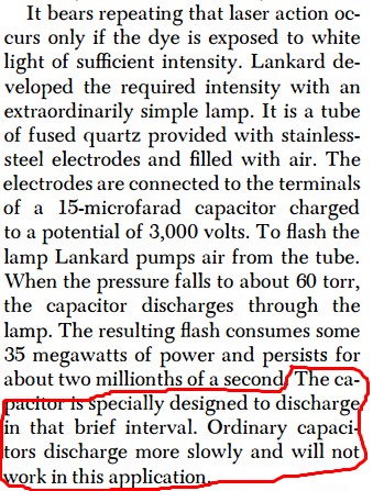
As you can see, the circuit is adapted to our realities in terms of elemental base and network voltage. However, in the original scheme it is proposed to add a preionization circuit for the lamp, which was omitted in the adapted one. Also in the original circuit, a high-voltage power transformer from an oscilloscope is proposed as a power transformer. And judging by the output voltage, I meant the winding of the CRT power supply of this very oscilloscope. The person who translated the article most likely understood everything correctly, but in a fit of adaptation to our realities, he probably remembered TVs (it’s easier to disassemble a TV in any way than an oscilloscope), where the CRT is powered by a high-voltage winding of a horizontal transformer. Therefore, he called the power transformer in the adapted circuit “TVS”, similar to a horizontal transformer. As you know, a typical fuel assembly is wound on a ferrite core and cannot operate at a frequency of 50 Hz. And these are very annoying mistakes, which reduce the probability of successful laser operation to zero. The fact is that for a dye laser, the flash duration, which lies in the microsecond range, is very critical. The proposed preionization chain in the original article allows one to accelerate the development of the discharge in the lamp and shorten the duration of the flash. And it is also advisable to make as tight a structure as possible, with as short conductors as possible. Moreover, in the original article it is written that the storage capacitor must have a small stray inductance. More precisely, "it should be designed for short duration discharges." And they directly specified that ordinary capacitors would not work - the laser would not work with them. In an adapted article, they decided not to mention such an insignificant thing. Let's compare the text of the original and adaptation. Red indicates the requirement of a low inductance capacitor.
In an adapted article about a low-inductance capacitor were silent. And if they were silent, it means you can run after the first electrolytes that come across, the use of which will make the laser impossible.
This alone is enough to make the attempt to “blindly” repeat what was described in the article from “UT” ended in complete collapse, since the need for a low-inductance capacitor is completely unobvious to either an untrained “repeater” or even an ordinary teacher of a technical circle. Unless of course he is savvy in laser technology. I’m silent about the fuel assemblies, it would be more correct to recommend at least a “power transformer from an oscilloscope”.
I also note that in the original article there is an addition on how to make a device from a diffraction grating for tuning the laser wavelength, which was also ignored in the adapted article.
What to do if you still wanted to build a dye laser yourself? First you need to read specialized literature. And even better - foreign primary sources. Fortunately, there are already alternatives to the UT article. The most detailed and thorough description is on the site of the well-known do-it-yourselfer Yun Sothory.
The material is a compilation of extracts from specialized articles and his extensive personal experience, therefore, you can safely use it.
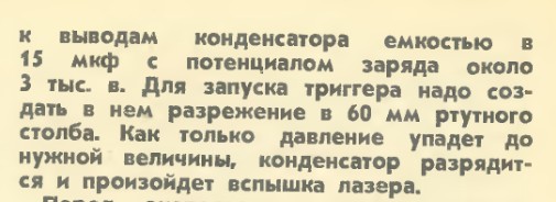
And now I propose to look inside the already “real” dye lasers produced in series. First, let's look inside the LOS-4M pulsed laser, in some sources called the "Rainbow".
This is a tube-pumped laser with a declared output energy of 1 J without wavelength selection. Adding a selective element (diffraction grating) to the optical resonator reduces the output energy, but allows you to adjust the radiation wavelength.
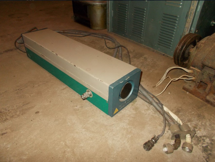
The ability to select the radiation wavelength is the most valuable property of dye lasers and it can be implemented in different ways. You can set the diffraction grating or prism behind the output mirror of the resonator, you can install it inside the resonator. In the second case, a narrower emission line is achieved. In addition to the grating or prism, the principle of which is obvious, they also use polarizing filters, which are described below.
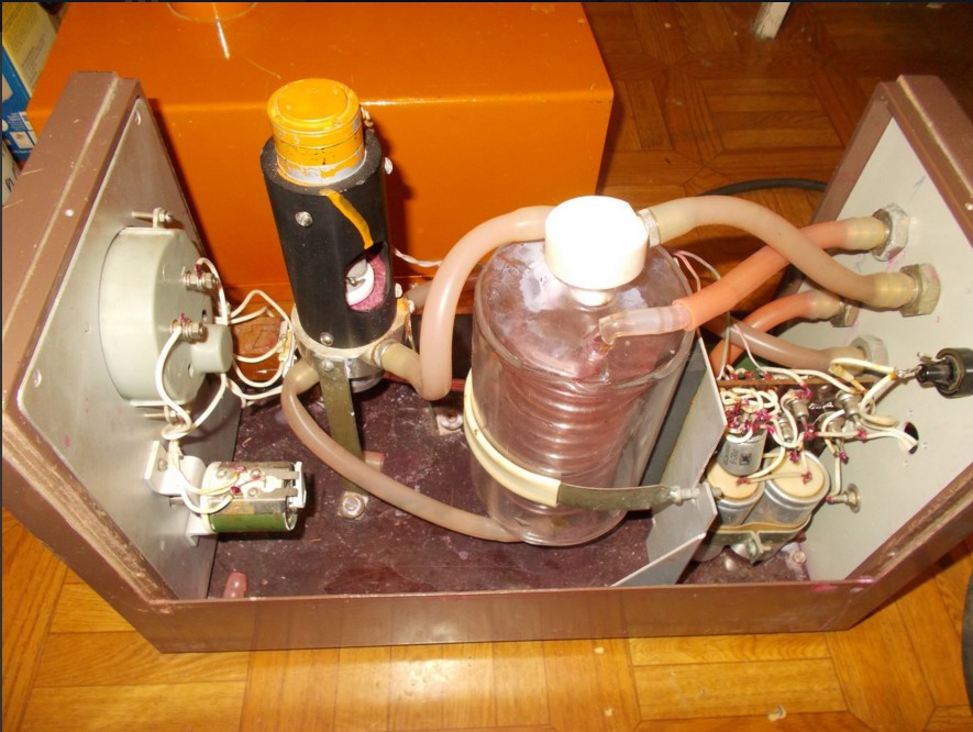
As you can see, the device of the emitter is almost identical to the classic solid-state laser, only instead of the rod of the laser crystal or glass is the tube through which the dye solution flows. Outside, this tube is surrounded by another, through which a filter solution flows, designed to cut off the short-wave UV from the pump lamps, which quickly destroys the dye. Pumping is carried out by two IFP-1200 lamps. The resonator is formed by a dull mirror hidden at the end of the quantron and translucent at a distance from it.
Between the quantron and the output mirror there is a holder for the diffraction grating, the position of which can be adjusted with a micrometer screw. Dye and filter solutions are supplied through the hoses. The radiator is connected to the power supply by coaxial cables, which have low spurious parameters.
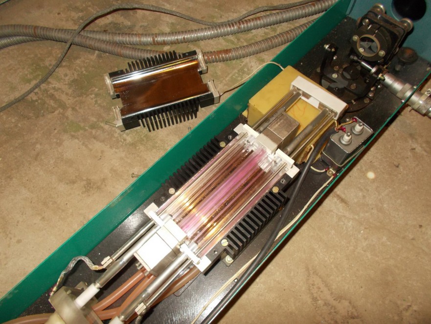
Now let's look at the power supply.
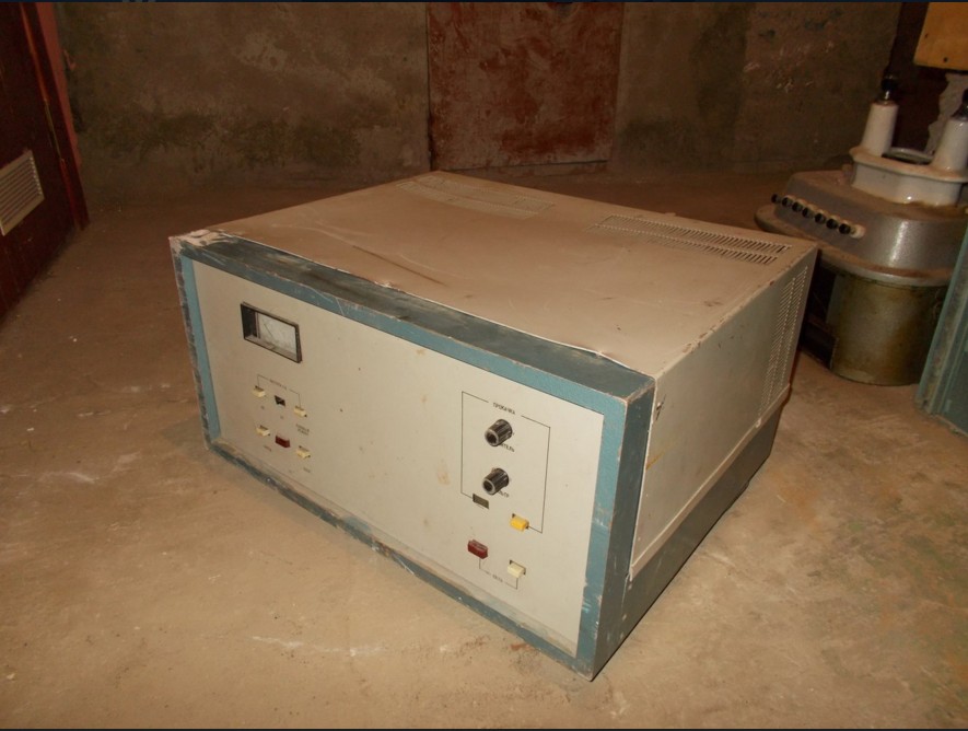
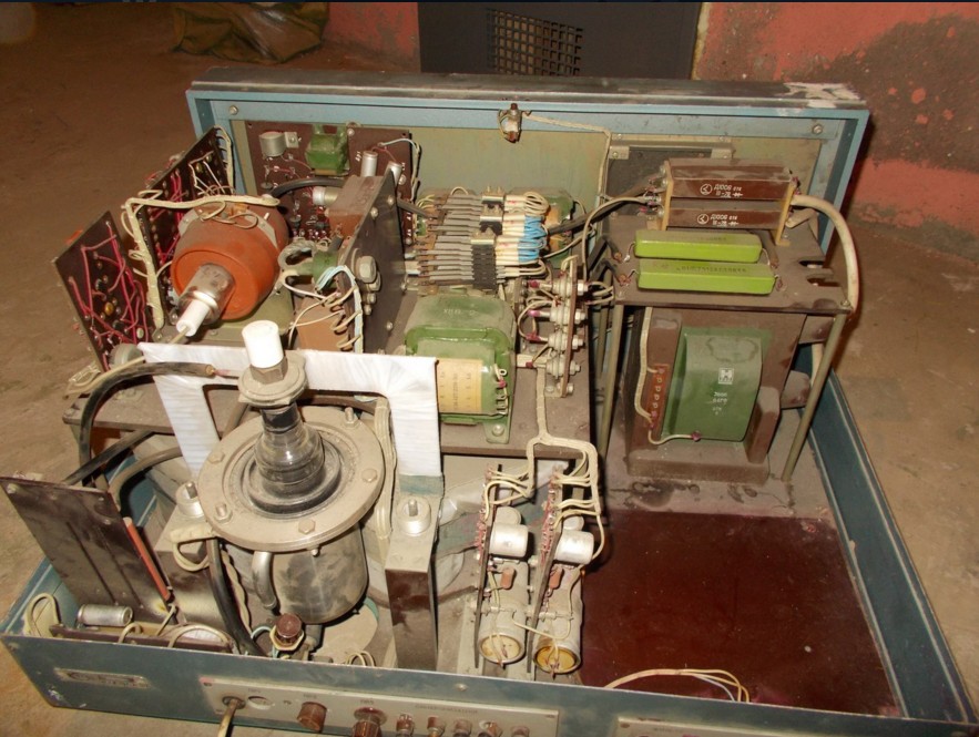
In the foreground, the IRT-2 ignitron arrester is striking. The fact is that the capacitor bank is charged to a voltage that obviously exceeds the self-breakdown voltage of the IFP-1200 lamps. In order for the laser to work in a controlled mode and shoot when we need it, and not when it wants to, then we used a control element in the form of this arrester. Its advantages are that it is able to commute a lot of energy in one pulse, has small parasitic parameters, has a very long service life and does not require any maintenance, unlike traditional spark arresters, which require periodic adjustment of the spark gap and cleaning of contacts. On the right in the corner is a high-voltage transformer with a rectifier and ballast resistances for charging capacitors. On the large plate to the left of the transformer, auxiliary electronics are placed to control the ignitron discharger and the process of charging capacitors. Capacitors are located underneath.
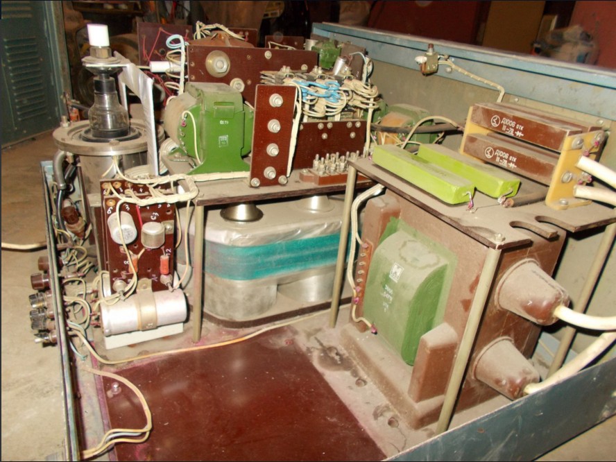
There are 6 capacitors for each pump lamp, each with a capacitance of 2 μF, and a voltage of 5 kV. Capacitors of a low inductive series k75-30. In total, 12 microfarads of 5 kV for each lamp are obtained. As you can see, the capacitance used in a serial laser is quite close to that indicated in the articles for independent repetition.
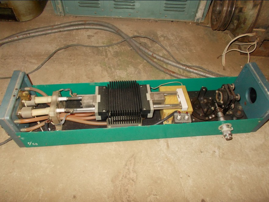
Where there is free space in the power supply, containers with dye and filter and pumps for their circulation were placed. I got the power supply without them, so I have to use an external circulation unit. It consists of a pump operating at low constant voltage (27V) and a quartz tank with a spiral soldered into it. Water is passed through the spiral to cool the dye, since it rises when the temperature rises.

Since I am still busy with other projects, the restoration of the working state of this laser is only in the plans so far, and the device itself has so far been “put in the dust”. It is worth noting that there are dye lasers that use laser pumping - from another pulsed laser in the visible or ultraviolet range. They are currently the most common. In addition, there were prototypes of lasers in which a plastic active element stained with the corresponding organic compound was used instead of a dye solution. They use pumping by a pulsed laser, but the lifetime of the AE is quite limited, therefore, such lasers are not spread.
To pump LRK, a nitrogen laser with a wavelength of 337 nm (UV) or an excimer (wavelength and energy depends on the selected gas mixture) is used, or pulsed neodymium with a frequency doubling (532 nm) or tripling (355 nm) or even quadrupling (266 nm) frequency. In some cases, the copper vapor laser I have already described is used . In these cases, the dye laser itself is a “passive” device that does not require power, except for the dye circulation pump. But if you need a large (up to tens-hundreds of joules) generation energy, then there is no alternative to vacuum pumping.
After reviewing the classical pulsed dye laser, one may wonder what to do if one needs radiation characteristic of a dye laser, with its inherent ability to tune the wavelength, but with the continuous mode? And here, too, a way out was found. Consider it with the example of a laser from the American company Coherent.
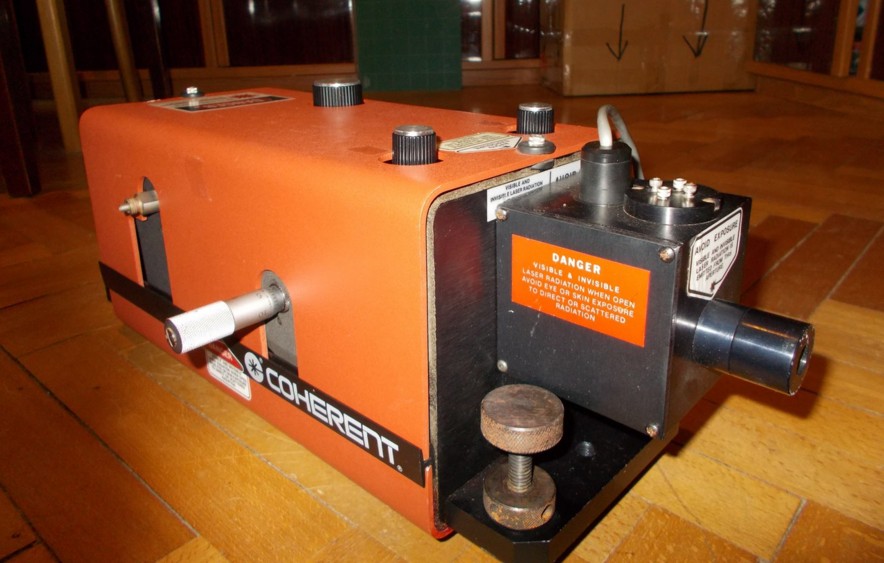
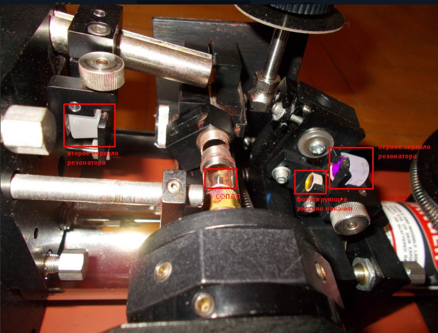
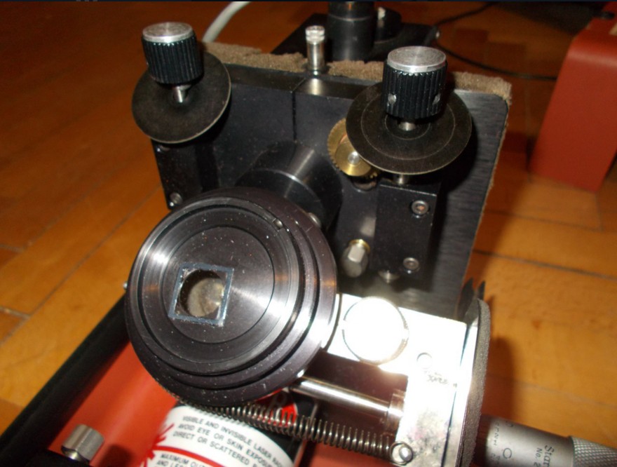
Inside this laser is a complex optical system consisting of optics for “delivering” a pump beam and an optical resonator with a polarization wavelength selector.
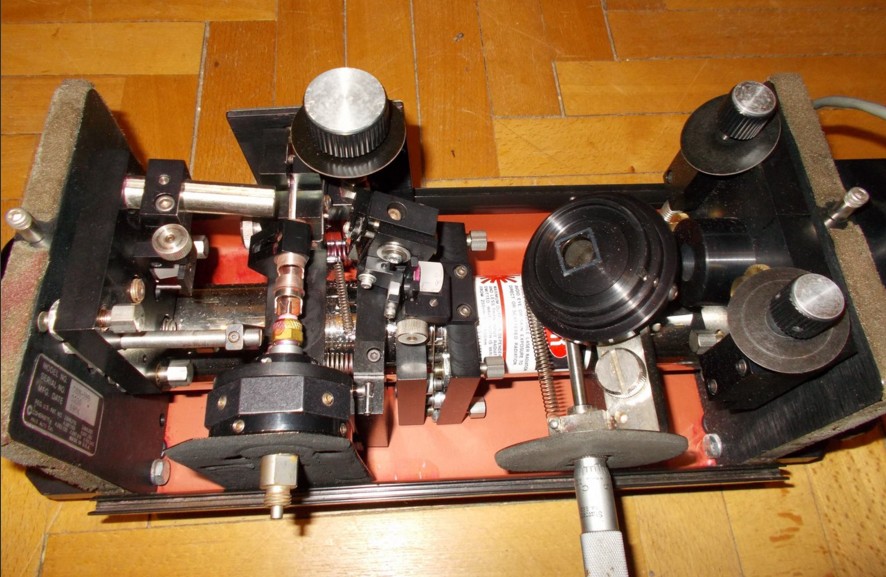
If the pump laser beam is focused inside a thin and fast-flowing laminar jet of a dye solution, lasing can be achieved in a continuous mode. The energy density of the pump is needed very high, and that the dye does not overheat, you need a fast-flowing jet. The pump source most often used is a powerful argon laser, the beam of which is focused by a selective concave mirror into the jet. An argon laser is best suited for pumping dyes from the rhodamine group, its initial beam is very thin and focuses easily into the thinnest spot. The jet is formed by a nozzle from a flattened stainless tube.
This photo did not fit the polarization wavelength selector and the third, output mirror of the resonator.
To obtain a laminar flow, a dye solution in ethylene glycol of a given temperature and viscosity is needed, and a special pump is used for pumping. From the pump beam, the jet shines with spontaneous radiation, and the radiation that appears between the tuned resonator mirrors is amplified and converted into a laser beam. Inside the resonator, a polarization wavelength selector is installed, consisting of a stack of quartz plates. It works like this. The laser beam in the resonator is polarized, and the filter is installed at a certain angle, passing a certain angle of polarization. Laser radiation of different wavelengths has a different polarization angle, and consequently, uneven losses in the filter. Thus, the wavelength at which the polarization angle ideally slides through the filter receives the greatest gain, and the rest are suppressed.
The greatest efficiency is achieved when using a solution of rhodamine-6G. The output radiation power reaches 4 watts at 12 watts of pumping. Unfortunately, this laser will be on my shelf, since I do not have a full-time solution pumping system, nor do I have a powerful argon laser, although I have been looking for it for a long time.
Then I visualized the path of the pump beam using a small argon laser, the solution was not supplied to the nozzle.

So here is a small overview of the most common dye lasers and those important points that you need to remember when trying to build such a laser yourself. Do not repeat the mistakes described in the article from the children's magazine.
Despite this, neither me nor my colleagues are aware of the precedents for the successful construction of a dye laser, guided by this article. Why is that? What are the hidden pitfalls in dye lasers? How are industrial dye lasers arranged? Let's figure it out.
The dye laser is very attractive for DIY. Since it does not need scarce and hard-to-reach crystals or glasses, or complex glass-blowing work as for the manufacture of active elements of gas lasers. It consumes very little energy and produces bright visible light. Its radiation has a very valuable property - it can be decomposed into the spectrum and highlight the desired color of the beam.
To begin with, it should be noted that the article from UT No. 8 of 1971, which was then re-issued in No. 11 of 1992, is not original. This is an adaptation of an article published in the “The amateur scientist” column of the American journal “Scientific American” in the February 1970 issue. And everything would be fine (maybe!) If this adaptation were not performed with unacceptable reductions and annoying errors. First, let's look at the volume of both articles. The original article occupied 6 pages, adapted at UT - only 3 pages. Pictures are copied practically 1 in 1. The original American article can be downloaded from here, having stolen it from evil copywriters through sci-hub. Or already from the file hosting .
Compare the similarity of the pictures in the original and adapted articles.
Original:
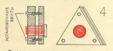
Now let's look at the pictures from UT:
On this, the similarities in the pictures end and the differences begin. For example, compare the electrical circuits shown in the original and adapted articles.
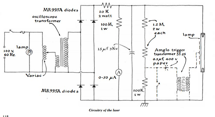
Original:
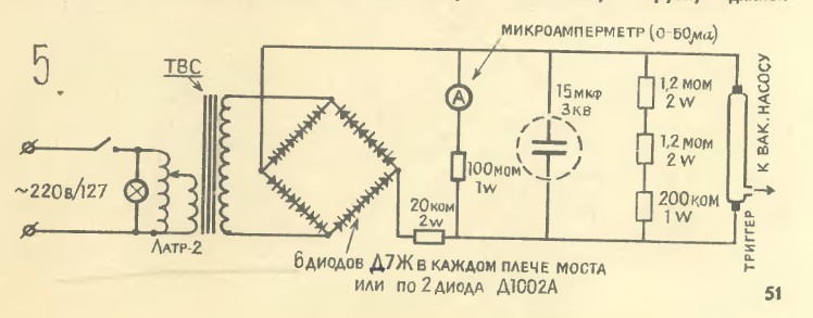
Adaptation:
As you can see, the circuit is adapted to our realities in terms of elemental base and network voltage. However, in the original scheme it is proposed to add a preionization circuit for the lamp, which was omitted in the adapted one. Also in the original circuit, a high-voltage power transformer from an oscilloscope is proposed as a power transformer. And judging by the output voltage, I meant the winding of the CRT power supply of this very oscilloscope. The person who translated the article most likely understood everything correctly, but in a fit of adaptation to our realities, he probably remembered TVs (it’s easier to disassemble a TV in any way than an oscilloscope), where the CRT is powered by a high-voltage winding of a horizontal transformer. Therefore, he called the power transformer in the adapted circuit “TVS”, similar to a horizontal transformer. As you know, a typical fuel assembly is wound on a ferrite core and cannot operate at a frequency of 50 Hz. And these are very annoying mistakes, which reduce the probability of successful laser operation to zero. The fact is that for a dye laser, the flash duration, which lies in the microsecond range, is very critical. The proposed preionization chain in the original article allows one to accelerate the development of the discharge in the lamp and shorten the duration of the flash. And it is also advisable to make as tight a structure as possible, with as short conductors as possible. Moreover, in the original article it is written that the storage capacitor must have a small stray inductance. More precisely, "it should be designed for short duration discharges." And they directly specified that ordinary capacitors would not work - the laser would not work with them. In an adapted article, they decided not to mention such an insignificant thing. Let's compare the text of the original and adaptation. Red indicates the requirement of a low inductance capacitor.
In an adapted article about a low-inductance capacitor were silent. And if they were silent, it means you can run after the first electrolytes that come across, the use of which will make the laser impossible.
This alone is enough to make the attempt to “blindly” repeat what was described in the article from “UT” ended in complete collapse, since the need for a low-inductance capacitor is completely unobvious to either an untrained “repeater” or even an ordinary teacher of a technical circle. Unless of course he is savvy in laser technology. I’m silent about the fuel assemblies, it would be more correct to recommend at least a “power transformer from an oscilloscope”.
I also note that in the original article there is an addition on how to make a device from a diffraction grating for tuning the laser wavelength, which was also ignored in the adapted article.
What to do if you still wanted to build a dye laser yourself? First you need to read specialized literature. And even better - foreign primary sources. Fortunately, there are already alternatives to the UT article. The most detailed and thorough description is on the site of the well-known do-it-yourselfer Yun Sothory.
The material is a compilation of extracts from specialized articles and his extensive personal experience, therefore, you can safely use it.
And now I propose to look inside the already “real” dye lasers produced in series. First, let's look inside the LOS-4M pulsed laser, in some sources called the "Rainbow".
This is a tube-pumped laser with a declared output energy of 1 J without wavelength selection. Adding a selective element (diffraction grating) to the optical resonator reduces the output energy, but allows you to adjust the radiation wavelength.
The ability to select the radiation wavelength is the most valuable property of dye lasers and it can be implemented in different ways. You can set the diffraction grating or prism behind the output mirror of the resonator, you can install it inside the resonator. In the second case, a narrower emission line is achieved. In addition to the grating or prism, the principle of which is obvious, they also use polarizing filters, which are described below.
As you can see, the device of the emitter is almost identical to the classic solid-state laser, only instead of the rod of the laser crystal or glass is the tube through which the dye solution flows. Outside, this tube is surrounded by another, through which a filter solution flows, designed to cut off the short-wave UV from the pump lamps, which quickly destroys the dye. Pumping is carried out by two IFP-1200 lamps. The resonator is formed by a dull mirror hidden at the end of the quantron and translucent at a distance from it.
Between the quantron and the output mirror there is a holder for the diffraction grating, the position of which can be adjusted with a micrometer screw. Dye and filter solutions are supplied through the hoses. The radiator is connected to the power supply by coaxial cables, which have low spurious parameters.
Now let's look at the power supply.
In the foreground, the IRT-2 ignitron arrester is striking. The fact is that the capacitor bank is charged to a voltage that obviously exceeds the self-breakdown voltage of the IFP-1200 lamps. In order for the laser to work in a controlled mode and shoot when we need it, and not when it wants to, then we used a control element in the form of this arrester. Its advantages are that it is able to commute a lot of energy in one pulse, has small parasitic parameters, has a very long service life and does not require any maintenance, unlike traditional spark arresters, which require periodic adjustment of the spark gap and cleaning of contacts. On the right in the corner is a high-voltage transformer with a rectifier and ballast resistances for charging capacitors. On the large plate to the left of the transformer, auxiliary electronics are placed to control the ignitron discharger and the process of charging capacitors. Capacitors are located underneath.
There are 6 capacitors for each pump lamp, each with a capacitance of 2 μF, and a voltage of 5 kV. Capacitors of a low inductive series k75-30. In total, 12 microfarads of 5 kV for each lamp are obtained. As you can see, the capacitance used in a serial laser is quite close to that indicated in the articles for independent repetition.
Where there is free space in the power supply, containers with dye and filter and pumps for their circulation were placed. I got the power supply without them, so I have to use an external circulation unit. It consists of a pump operating at low constant voltage (27V) and a quartz tank with a spiral soldered into it. Water is passed through the spiral to cool the dye, since it rises when the temperature rises.
Since I am still busy with other projects, the restoration of the working state of this laser is only in the plans so far, and the device itself has so far been “put in the dust”. It is worth noting that there are dye lasers that use laser pumping - from another pulsed laser in the visible or ultraviolet range. They are currently the most common. In addition, there were prototypes of lasers in which a plastic active element stained with the corresponding organic compound was used instead of a dye solution. They use pumping by a pulsed laser, but the lifetime of the AE is quite limited, therefore, such lasers are not spread.
To pump LRK, a nitrogen laser with a wavelength of 337 nm (UV) or an excimer (wavelength and energy depends on the selected gas mixture) is used, or pulsed neodymium with a frequency doubling (532 nm) or tripling (355 nm) or even quadrupling (266 nm) frequency. In some cases, the copper vapor laser I have already described is used . In these cases, the dye laser itself is a “passive” device that does not require power, except for the dye circulation pump. But if you need a large (up to tens-hundreds of joules) generation energy, then there is no alternative to vacuum pumping.
After reviewing the classical pulsed dye laser, one may wonder what to do if one needs radiation characteristic of a dye laser, with its inherent ability to tune the wavelength, but with the continuous mode? And here, too, a way out was found. Consider it with the example of a laser from the American company Coherent.
Inside this laser is a complex optical system consisting of optics for “delivering” a pump beam and an optical resonator with a polarization wavelength selector.
If the pump laser beam is focused inside a thin and fast-flowing laminar jet of a dye solution, lasing can be achieved in a continuous mode. The energy density of the pump is needed very high, and that the dye does not overheat, you need a fast-flowing jet. The pump source most often used is a powerful argon laser, the beam of which is focused by a selective concave mirror into the jet. An argon laser is best suited for pumping dyes from the rhodamine group, its initial beam is very thin and focuses easily into the thinnest spot. The jet is formed by a nozzle from a flattened stainless tube.
This photo did not fit the polarization wavelength selector and the third, output mirror of the resonator.
To obtain a laminar flow, a dye solution in ethylene glycol of a given temperature and viscosity is needed, and a special pump is used for pumping. From the pump beam, the jet shines with spontaneous radiation, and the radiation that appears between the tuned resonator mirrors is amplified and converted into a laser beam. Inside the resonator, a polarization wavelength selector is installed, consisting of a stack of quartz plates. It works like this. The laser beam in the resonator is polarized, and the filter is installed at a certain angle, passing a certain angle of polarization. Laser radiation of different wavelengths has a different polarization angle, and consequently, uneven losses in the filter. Thus, the wavelength at which the polarization angle ideally slides through the filter receives the greatest gain, and the rest are suppressed.
The greatest efficiency is achieved when using a solution of rhodamine-6G. The output radiation power reaches 4 watts at 12 watts of pumping. Unfortunately, this laser will be on my shelf, since I do not have a full-time solution pumping system, nor do I have a powerful argon laser, although I have been looking for it for a long time.
Then I visualized the path of the pump beam using a small argon laser, the solution was not supplied to the nozzle.
So here is a small overview of the most common dye lasers and those important points that you need to remember when trying to build such a laser yourself. Do not repeat the mistakes described in the article from the children's magazine.