How to control electrical appliances, radio-controlled models, motorized sidecar using a glance
- Tutorial
In my previous articles, I talked about how to help paralyzed people communicate with the outside world: communicate their desires, write letters, surf the Internet, using only their eyes and a device that tracks the direction of gaze (Aytreker). In this case, physically, a person still remains limited to the world of the computer and the bed.
Here I will talk about the simplest (in my opinion) ways to change something in the outside world: turn on the light or festoon on the Christmas tree, control the rover on the radio, make the motorized stroller move in the right direction.
Content
Introduction
Required Components
Connecting the Arduino to a Computer
Power
Control Circuit Motor Control Circuit
Introduction
In addition to the eye tracking device and the free software for it, described here in this article, we will need something that connects the computer to external objects.
Despite the availability of various devices on sale which can be controlled from a computer, the simplest and cheapest option seemed to me to use two parts: an Arduino board and a board with several relays.
If you have never encountered Arduino, still do not stop reading, in the future you will see that in this context it is quite simple to work with it, there is a lot of Arduino-based children's designers for sale.
At the same time, if you are not familiar with electrical safety and have never done electrical wiring in the house, do not try to repeat the schemes that use the connection to the sockets!
All you need to know about Arduino is a small device that can be plugged into a computer's USB connector, after which it can turn on / off electrical signals on its contacts according to the instructions received.
The signals are quite low-power, so to control something more powerful (with light bulbs, for example), we will install a relay unit, which in response to the signal from the Arduino will close-open the control contacts of external devices. In addition, the relays isolate the electrical circuits of the computer + Arduino from the electrical circuits of the controlled device.
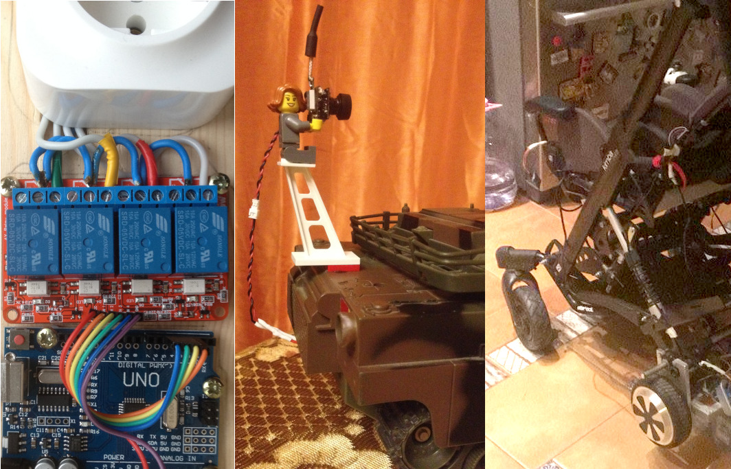
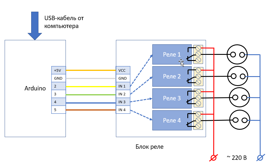
So, the basis of the control circuits for electrical outlets and motors, which will be further described, is as follows: two parts connected by wires between themselves, connected by a USB cable to a computer and wires to what we want to control:

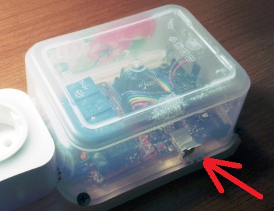
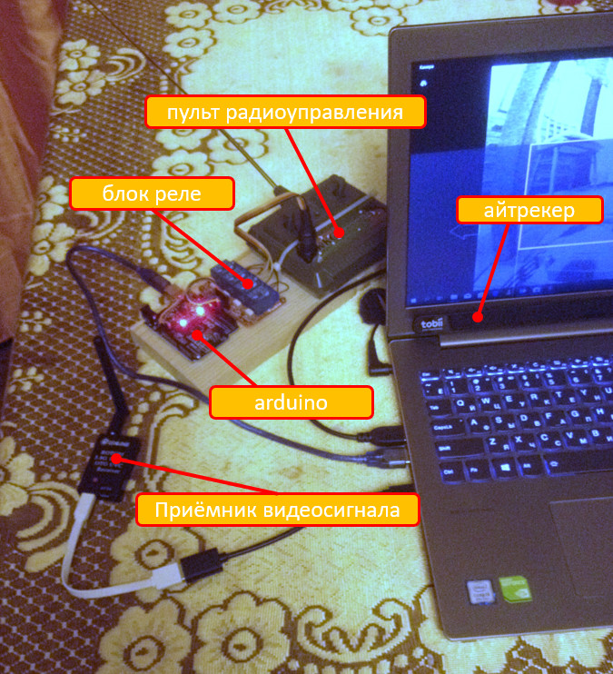
In the real world, it might look like this:
We send a command from a computer, Arduino one of its contacts turns on / off the relay, which is a switch of a device or a separate button on the device.
Required components
We will need (prices in 2018 in the local store are shown in brackets. Those who can buy in China can save a lot in money but lose in time):
1) Arduino UNO board with USB cable (you can replace the original CH340 instead of expensive FTDI) (450 rub.
2) A board with four relays operating from a voltage of 5 volts and capable of controlling devices with a voltage of 220 volts. (450 rubles). There are still boards that work at 12 volts, do not confuse!
3) A bundle of wires for connecting two boards. In my case, it took wires with a socket on one side and a pin on the other, since the relay unit has pin contacts, and the Arduino has sockets. Look, what connectors on your boards, buying wires (150 rubles).

Connection of Arduino to the computer
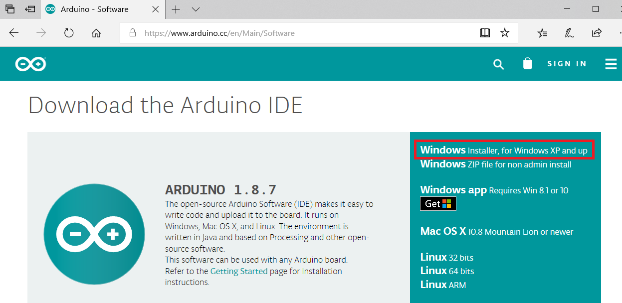
To begin, install the Arduino programming software from www.arduino.cc :
On the page https://www.arduino.cc/en/Main/Software, click on “Windows Installer”:
Click “Just Download”:

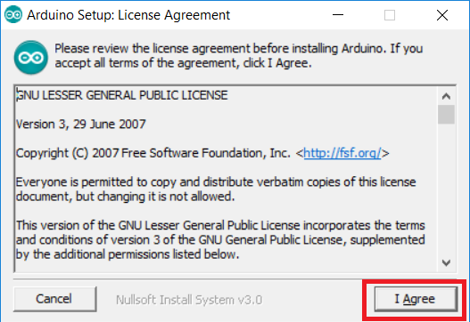
Download and run the program -installer: We

agree on everything:


After the installation is completed, we connect the Arduino board and the computer with the USB cable.
The lights will light up on the Arduino board, and in the device manager you will see that a new port has appeared, and it has been assigned a certain number, for example, COM3:
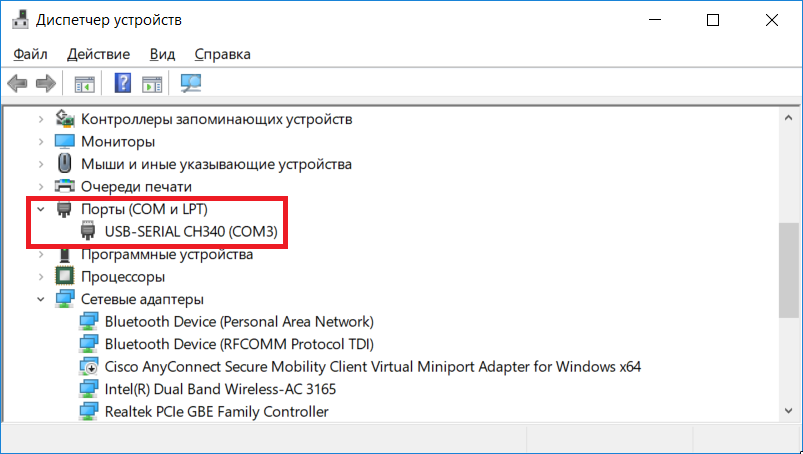
Let's change its number to COM9, since in the future everything will be tied to COM9. To do this, click on it with the right mouse button, call the context menu and select “properties” in it:

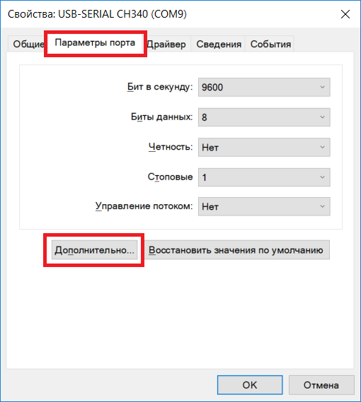
On the “port settings” tab, click the “Advanced” button:
And finally, select “COM9” as the COM port number.
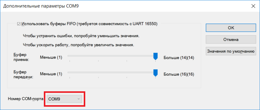
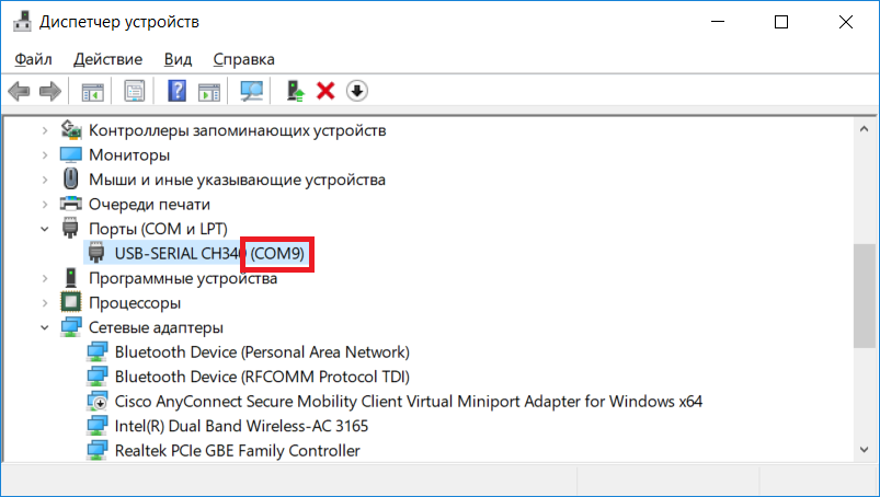
Close all open windows with the “OK” button, then remove and insert the USB cable to check that the Arduino will later be connected via COM9 if it is inserted into the same USB connector on the computer:
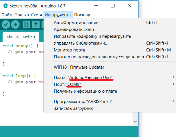
Now we will call and configure the newly installed one Arduino:

In the “Tools” menu, set the “Arduino UNO” board, and the port - “COM9”:
Now everything is ready to assemble the circuits and breathe life into them.
Control circuit of power outlets
If you are not familiar with electrical safety and have never done electrical wiring in the house, do not try to repeat this scheme! The circuit uses life-threatening stress!
Once again, test questions:
- Do you know how to distinguish a wire with a phase from a wire with a zero in the socket?
- Do you know how to ring the wires and make sure that there is no short circuit after plugging into the outlet?
If you are unsure of answering these questions, ask someone more experienced to compile a scheme.
Now to the point.
It works like this:
The wiring diagram of the sockets is as follows:
Zero is fed to the sockets directly, and the phase through the relay. If you do the opposite, it will work, but there will be a danger of electric shock from disconnected FAULT devices. That is, grabs the switched off faulty TV, and it beats you with a current.
If the house has a protective earth, then use a grounded sockets.
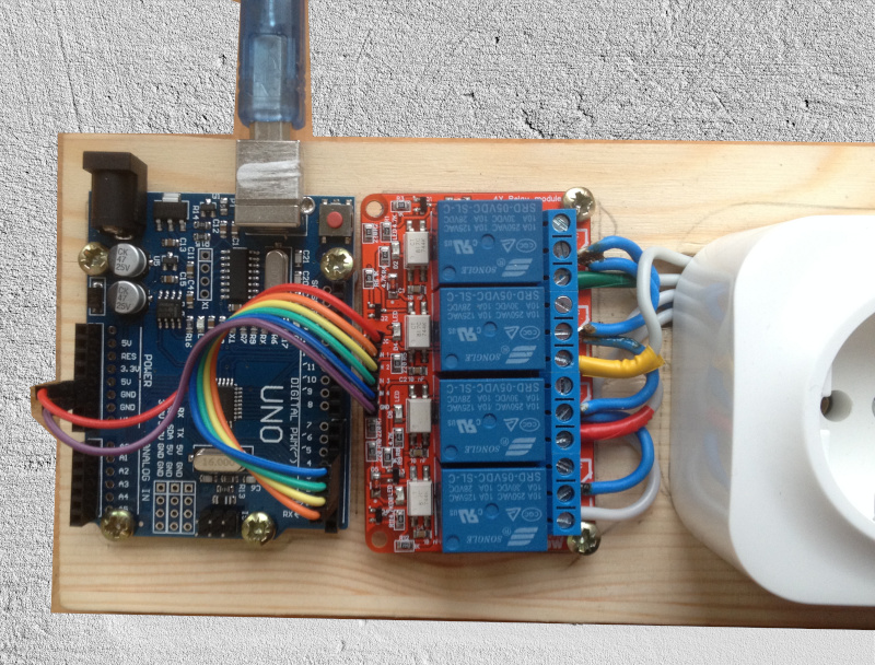
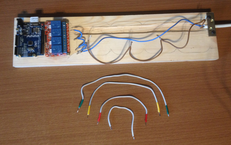
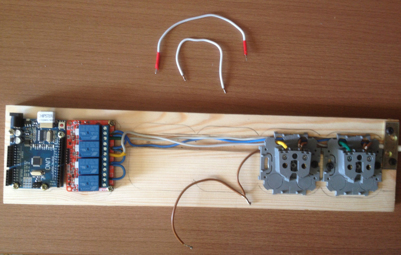
Next is my reference design. In it, I made a mistake with the color of the wires: the color of the neutral wire was made brown, and the phases - blue. Pay attention to this.
We take a piece of board of a suitable size to fit on it (from left to right): Arduino, relay unit, four sockets, bracket for pressing the wire to the board.

Saw off the excess and make a chisel with a chisel for wires so that they fit freely under the sockets.

Boards of Arduino and the block of the relay are fastened with screws to the board, paving plastic washers.

If the puck was not at hand, you can cut dowels:

Prepare the wires: cut to the desired length and strip out of insulation. It is desirable to tin them with a soldering iron in places of contacts with sockets and relays.
We will press the wire to the board with the help of the bracket so that it cannot be pulled out.

We connect the wires and screw the sockets. We call the chain.

We connect the Arduino board with the relay unit with a bundle of wires in accordance with the above diagram.
Close the board with a protective casing of non-conductive material.Here it must be done, as life-threatening voltage approaches the relay unit! In extreme cases, at least shake tape contacts at the relay.
I used as a casing a container for products made of hard plastic, attaching it with self-tapping screws:

Do not forget to make a hole for the USB cable.
Connect the device to the computer, but do not turn it on .
Run the program “Arduino” and copy this program text there:
// Реле подключены к пинам 2,3,4,5int Relay1=2, Relay2=3, Relay3=4, Relay4=5;
voidsetup(){
pinMode(Relay1,OUTPUT);
pinMode(Relay2,OUTPUT);
pinMode(Relay3,OUTPUT);
pinMode(Relay4,OUTPUT);
Serial.begin(9600);
}
voidloop(){
 delay (200);
  // 1. Принимаем команду от компьютераwhile(Serial.available())
  {
    switch(Serial.read())
    {
     case'0': // первое реле выключить
      digitalWrite(Relay1,0);
      break;
     case'1': // первое реле включить
      digitalWrite(Relay1,1);
      break;
     case'2': // второе реле выключить
      digitalWrite(Relay2,0);
      break;
     case'3': // второе реле включить
      digitalWrite(Relay2,1);
      break;
     case'4': // третье реле выключить
      digitalWrite(Relay3,0);
      break;
     case'5': // третье реле включить
      digitalWrite(Relay3,1);
      break;
     case'6': // четвертое реле выключить
      digitalWrite(Relay4,0);
      break;
     case'7': // четвертое реле включить
      digitalWrite(Relay4,1);
      break;
    } // switch
  } // while
}
Then click on the program download button in the Arduino (see picture below). If everything went without errors, then we see the inscription “Download complete”.

Let's check that our device executes commands. To do this, call the port monitor:

Now type in the number 1 there and press Enter or the "Send" button: A

characteristic click of the relay will be heard and the contact in the first outlet will connect to the phase wire. Check it with a tester. Then dial the number 0 and the relay will disconnect the contact.
Looking at the text of the program, you can see what happens if we type other numbers:
3.2 - turn on, turn off the second outlet
5.4 - turn on, turn off the third outlet
7.6 - turn on, turn off the fourth outlet
Check the tester for the connection of these sockets. After checking, you can connect the wire to the mains voltage and start turning on / off real devices.
Our next task is to turn the devices on and off with a glance. To do this, we will configure the bkb program , described here in this article, (LAST VERSION OF THE PROGRAM IS NEEDED !!!) .
Suppose we want to turn on and off the lamp and Christmas tree garland.
In the standard Paint program, draw four 200x200 patterns in the BMP format :
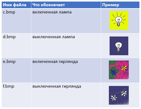
Create four command files: c.cmd, d.cmd, e.cmd, f.cmd
They will contain commands for sending to the COM9 port characters 1,0,3,2. And we remember that they turn the first and second sockets on and off. It is important that between the two lines in these files there are no empty lines!
c.cmd:
MODE COM9: BAUD=9600 DATA=8 STOP=1 PARITY=N to=off xon=off odsr=off octs=off rts=off idsr=off dtr=off
echo 1 > com9:
d.cmd:
MODE COM9: BAUD=9600 DATA=8 STOP=1 PARITY=N to=off xon=off odsr=off octs=off rts=off idsr=off dtr=off
echo 0 > com9:
e.cmd:
MODE COM9: BAUD=9600 DATA=8 STOP=1 PARITY=N to=off xon=off odsr=off octs=off rts=off idsr=off dtr=off
echo 3 > com9:
f.cmd:
MODE COM9: BAUD=9600 DATA=8 STOP=1 PARITY=N to=off xon=off odsr=off octs=off rts=off idsr=off dtr=off
echo 2 > com9:
Created files .bmp and .cmd rewrite the catalog grid program bkb .
After launching the bkb program in the table mode, a new, fifth row with our pictures will appear:

When we hold the view on the picture, the corresponding action is launched.
ATTENTION! The first time after starting the program, the action does not work. All subsequent times - it works. This is due to the fact that when the port is first initialized, the signal on the DTR line changes, which causes the Arduino to reboot, which lasts three seconds.
They say that this is solved with a soldering iron, but I did not dare to engage in such jewelry work. So for now just remember that the first time you need to include twice.
Note:
You probably already understood that in .cmd files you can call any external programs. If you have any device that can be controlled from the command line, you can execute such commands yourself, assigning necessary actions to any pictures in the table.
Motor control circuit
My friend upgraded the hoverboard and replaced the rear axle of the pram with it. Control was exercised by consoles through the Arduino board.
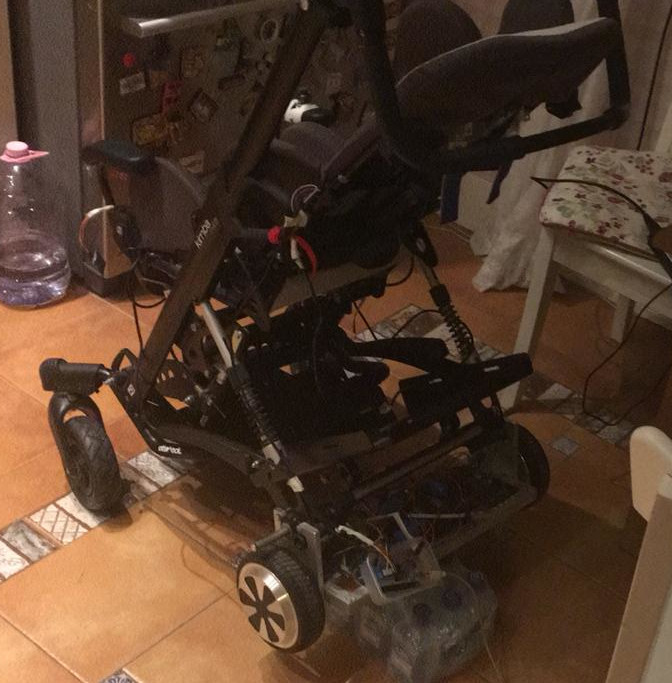
We decided to try to give the child the opportunity to control the stroller on their own with a glance. For this, the wheelchair control mode has been added to the bkb program .

After launching in this mode, arrows appear on the screen, a glance at which causes the program to send control characters to COM9, which are then interpreted by the stroller for moving forward / backward, turning left / right and stopping.
While the wheelchair is in a state of improvement, I decided to use the same program for remote control of the tracked tank model. This is also a pretty useful thing. First, the child gains skills that will be useful for managing the stroller. Secondly, this is just an exciting game.

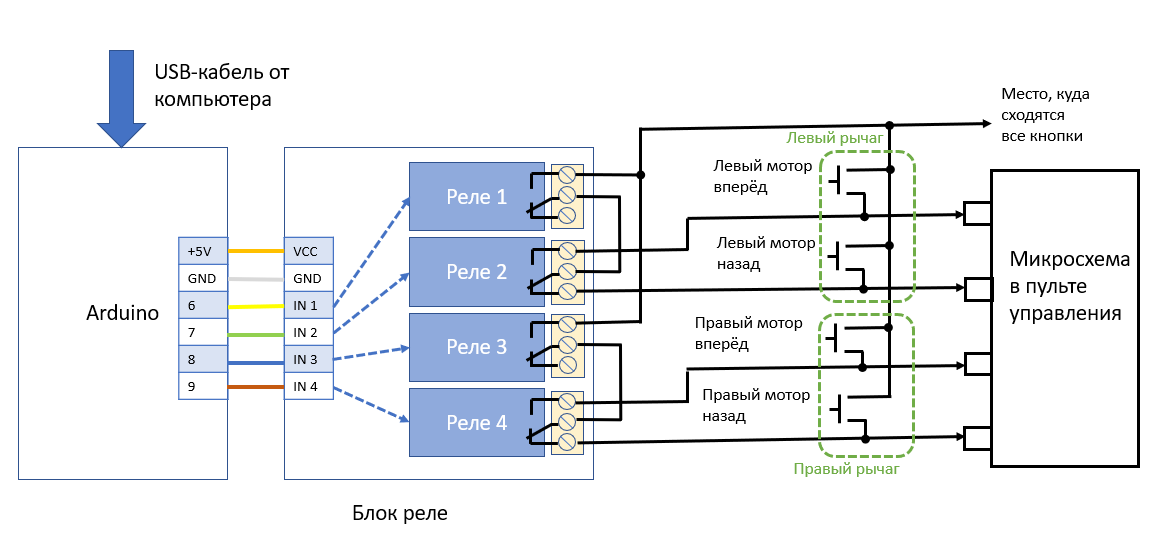
Each of the tracks of the tank is controlled by a lever that can be moved forward or backward. When moving the lever forward, he presses a button that causes the motor to rotate forward. When moving the lever back, he presses the button, which causes the motor to rotate in the opposite direction. Pressing two buttons at the same time - forward and backward is impossible.
The relay unit was connected to the remote control buttons as shown in the diagram below. The scheme does not allow activating the “motor forward” and “motor back” buttons simultaneously. One relay enables / disables the motor, and the second selects the direction forward or backward.
Find on the control panel board where the buttons are connected and connect to them according to the diagram below.
Please note that, unlike the previous scheme, Arduino controls the relay unit with pins 6 to 9.
I connected the relay unit with the console via a connector so that the console can be easily disconnected and used separately:

The program you need to download Arduino receives from the computer the same commands that are used to control the motorized sidecar:
F-forward
B-back
L-left
R-right
S-stop
Program text is shown below.
// Реле подключены к пинам 6,7,8,9int Relay1=6, Relay2=7, Relay3=8, Relay4=9;
int heartbeat=0; // для обнаружения разрыва связиvoidsetup(){
pinMode(Relay1,OUTPUT);
pinMode(Relay2,OUTPUT);
pinMode(Relay3,OUTPUT);
pinMode(Relay4,OUTPUT);
Serial.begin(9600);
}
voidRCStop(){
  digitalWrite(Relay1,0);
  digitalWrite(Relay2,0);
  digitalWrite(Relay3,0);
  digitalWrite(Relay4,0);
}
voidRCForward(){
  digitalWrite(Relay1,1);
  digitalWrite(Relay2,1);
  digitalWrite(Relay3,1);
  digitalWrite(Relay4,1);
}
voidRCBack(){
  digitalWrite(Relay1,1);
  digitalWrite(Relay2,0);
  digitalWrite(Relay3,1);
  digitalWrite(Relay4,0);
}
voidRCLeft(){
  digitalWrite(Relay1,1);
  digitalWrite(Relay2,0);
  digitalWrite(Relay3,1);
  digitalWrite(Relay4,1);
}
voidRCRight(){
  digitalWrite(Relay1,1);
  digitalWrite(Relay2,1);
  digitalWrite(Relay3,1);
  digitalWrite(Relay4,0);
}
voidloop(){
  // 1. Принимаем команду от компьютераwhile(Serial.available())
  {
    switch(Serial.read())
    {
      case'S': // Стоп машина!
      RCStop();
      heartbeat=0;
      break;
      case'F': // Ехать вперёд!
      RCForward();
      heartbeat=0;
      break;
      case'B': // Ехать назад!
      RCBack();
      heartbeat=0;
      break;
      case'L': // Поворот влево!
      RCLeft();
      heartbeat=0;
      break;
      case'R': // Поворот вправо!
      RCRight();
      heartbeat=0;
      break;
    } // switch
  } // while// 2. Обнаруживаем обрыв связи// Если треть секунды не было команд - отключаем моторы
  delay(10);
  heartbeat++;
  if(heartbeat>30)
  {
    heartbeat=30; // не расти же бесконечно!
    RCStop(); // связь потеряна - моторы выключаем
  }
}
If the connection with the computer is cut off (no symbols come for 0.3 sec, then the Arduino turns off the motors). This situation can be modeled by closing your eyes while controlling your gaze. Aytreker will not be able to determine the direction of the gaze and the signals will not be sent. Motors stop.
I equipped the model of the tank with a video camera, which is usually referred to as the exchange rate, or FPV (First Person View), which transmits an analog signal at a frequency of about 5.8 GHz. I took one of the cheapest cameras, also equipped with a transmitter and antenna: AKK BA-3. It cost me 1050 rubles. The camera with the transmitter is so small that it fits in the hands of the Lego figure:

All that needs to be done to operate the camera is to connect it to the power supply (from 3.2 to 5.5 Volts). Then the only button to select the range, frequency and power of the transmitter.
The camera heats up significantly, so I recommend setting the minimum power (25 milliwatts). In addition, I connected it to the battery of a tank with a voltage of 6 volts, which exceeds the allowable values. Therefore, I do not know how long it will last. You also recommend using a voltage regulator to power the camera.
When attaching the camera, I glued one element of the Lego to the tank, and the rest of the elements were already attached to it with a simple connection. This makes it easy to remove and remove the camera. Also, when crashing into an obstacle, the camera may simply fold, which will save it from damage.

To receive the video signal from the camera, I used the receiver Eachine ROTG01. He took not new for 1800 rubles. This is just a box with an antenna that connects to the computer's USB port and is visible as a USB camera. That is, launch the Camera application in Windows and see what the receiver is accepting. Even at the beginning, you need to hold down the single button of the receiver so that it scans the air and finds the frequency at which our camera transmits the signal.
In general, we will need three USB ports in the computer:
- for the eytreker
- for the Arduino, which controls the tank control panel
- for the video signal receiver
We launch the image output from the camera, for example, the Camera program. Run the bkb program and select the control mode of the motorized sidecar.
What can happen next is shown in the video:
It is seen that the speed of movement, and, especially, the speed of turns, is too big. So, if you choose a radio-controlled model, choose the slowest one. Excavator, perhaps, any.
Why not get a ready-made "spy robot"?
I got one in my hands, HappyCow 777-325.
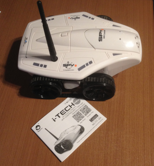
I was delighted: he has everything, remote control, video transmission, and he drives quite slowly. There is, however, one feature - it is controlled only through an application in Android or iOS. Well, this we will solve through the remote control of Android, for example, using scrcpy .
But it turned out that in addition to correctable flaws (a narrow angle of the camera), the machine has one uncorrectable. The video transmitted to them via Wi-Fi, has a monstrous delay.
That is, this robot has already crashed into something for a long time, while you are still pressing on the gas, thinking that it did not even reach the obstacle.
For a child who learns to remotely control the machine, this, in my opinion, is unacceptable.
So the robot gets retired. Although I would borrow the chassis from it.
Conclusion
I wish you all success in repeating and developing the described technical solutions.