Wave processes in hydraulic lines. The basics
Hi, Habr!
In the previous article, I talked about the method of characteristics, designed to calculate the wave processes in hydraulic lines. In fact, of course, the wave processes can be calculated in the mind, you only need to know the approach.
Under the cut, I will show “on the fingers” and using gifs, the main wave effects. As an example, I will use the hydraulic line again, but in fact it is based on practically the same equations as for acoustics and electrical lines. So, even if you are not hydraulics, maybe simple analogies will help you understand the wave processes in general.
Caution! Under the cat 15 MB animated gifs!So, here we will consider the propagation of one-dimensional plane waves in the hydraulic line. This assumption is quite true for long pipelines, whose length is many times greater than the internal diameter. Friction for simplicity is also neglected. In this case, the ongoing physical processes will be described by a pair of partial differential equations:
Where - density - speed, - pressure, - sound speed.
Unaccustomed to it, the form of these equations can be scary, but in fact everything is simple here. The first equation tells us that pressure will increase with time if more fluid flows into a pipe segment than flows (and the faster, the more dense and elastic the fluid is in the pipe); The second equation shows that in order to speed up a fluid segment, you need to attach a pressure difference to it (and, the greater the density, the more pressure difference must be applied to disperse the segment). Those. quite banal things are described: the liquid is compressible, the liquid has a mass.
Let us leave the analytical solution of these equations for future articles, let's go straight to the example “on the fingers”.
Take a pipe filled with water, in which the pressure is maintained at 100 bar (10 MPa) and the flow rate is 30 l / min. If a pressure step is applied to the left end, it predictably begins to move downstream at a speed equal to the speed of sound in the medium.
Of course, along with the pressure will change the value of the flow. If the pressure increases, it will “push” the fluid downstream and increase the flow rate, too, by some “step”. How much is determined by the value of the wave resistance. For pipe cross-sectional areafilled with liquid with a density and local sound speed , the characteristic impedance can be calculated as follows:
By dimension, this is the same as the usual hydraulic resistance, only used to calculate the pressure wave ratios () and consumption (), not their absolute values:
The greater the density and speed of sound, the higher the impedance will be, i.e. the more difficult it will be for a certain differential pressure to accelerate the liquid (increase the flow).
Now let's see how two waves behave moving towards each other:
If the pressure on the right end rises, the liquid will inevitably be slowed down by a negative differential. So the pressure increase wave going upstream will lead to a decrease in flow by an amount determined again by the characteristic impedance. That is, a wave of pressure rise and a drop in flow will move to the right.
In a collision it may seem that the flow waves are reflected from each other and go back. In fact, they simply overlap each other. This effect is also called interference:
Now we know that every pipe with liquid has such a property as wave resistance. It is interesting to see what will happen to the wave, if the diameter of a pipe at a certain section changes dramatically:
Until the wave reaches the place with a decrease in the diameter of the pipe, of course, nothing interesting happens. But then it reaches the section with higher wave resistance, which means that the ratio of the pressure wave to the flow wave must be greater than in the left portion of the pipe. This means that the pressure wave should increase, and the flow rate should decrease. At the same time, there is nothing left for the wave, except to reflect to the left, keeping equal values at the junction of two pipes.
For calculations it is convenient to use the reflection coefficientwhich is considered from the characteristic impedances of individual sections:
Then the reflected pressure and flow waves can be calculated as follows:
and these waves themselves will be superimposed by the law of interference with the original.
And this will look like a picture of the reflection of a wave from a section with a lower characteristic impedance:
It can be seen that this time the reflection coefficient is negative, which means the pressure wave after reflection will be less, and the flow rate, on the contrary, will be greater.
It must be remembered that the characteristic impedance depends not only on the size of the pipe, but also on the local speed of sound. Those. if we have a pipe section with a rubber sleeve, in which the speed of sound is significantly lower, then the wave will also be reflected:
First, it immediately catches the eye that the wave in the section with the rubber wall of the pipe moves slower. And once the wave impedance is lower, it means that the result of the reflection will resemble a case with the expansion of the pipe:
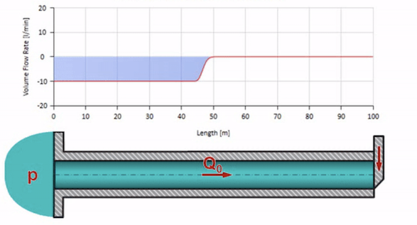
Now it would be nice to consider extreme cases with zero and infinitely large value of wave resistance. This will be the exit of the pipeline to the tank with constant pressure and closed end, respectively. I leave these animations without comment:
Well, if we combine these two cases, we get a classic hydraulic shock:
Here at the initial moment of time there is some value of flow, which is immediately equal to zero at the right end of the pipe (the valve is closed). To the left, a wave of falling flow and increasing pressure begins to move. These waves are reflected from the right end of the pipeline with zero characteristic impedance. In the absence of friction, this process will be endless.
Interestingly, using the above formulas, we can derive the Zhukovsky equation for a water hammer:
Express the flow rate through the speed, assuming that it falls from the given value to zero, and write the characteristic impedance:
We obtain the value of the pressure jump arising during the instantaneous closing of the valve.
Notes
- I was inspired to write an article by the head of the textbook on the basics of hydraulics of the hydraulic engineering department of the Rhine-Westphalian Technical University of Aachen, where, in my opinion, the processes in hydraulic lines are described most clearly (Grundlagen der Fluidtechnik Teil 1: Hydraulik, Hubertus Murrenhoff ISBN: 978-3-8440 -1223-1)
- Animations are made in the program SimulationX, the calculation was carried out by the method of characteristics