Improving the quality of gluing panoramas by coordinating the graph of projective transformations
Hi, Habr! Today we will tell about one of the ways to improve the quality of gluing panoramas. There is a widely used approach of gluing panoramas of flat objects, but since this approach is not without drawbacks, we offer our own improvement.
The task of panning is to build a single composite image based on a set of source images (see Fig. 1). It finds application in solving such practical tasks as:
- probing the surface of the Earth from a satellite or drone;
- gluing images taken with a microscope;
- gluing video;
- image acquisition in super resolution.
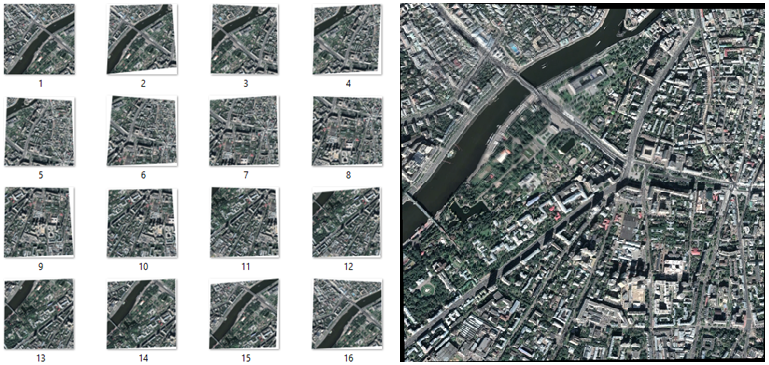
Figure 1 - Original Images and Panorama
In general, the algorithm for pasting a panorama can be formulated as follows [1] (see Fig. 2). At the very beginning, you need to extract a sufficient number of frames from the video stream. This can be done on-line by sequentially reading all the frames and selecting individual ones with the necessary frequency.
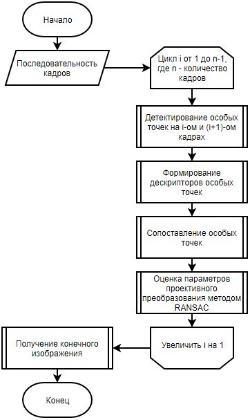
Figure 2 - A flowchart of the panorama gluing algorithm using singular points
After that, sequentially going through pairs of images from the set, one should perform the detection of singular points and the calculation of their descriptors on these images [2–4]. It is these singular points that make it possible to build a geometric correspondence between two frames. The following is a mapping of singular points based on their descriptors. It should be borne in mind that this does not exclude the possibility of obtaining false matches.
Further, having two sets of singular points, one should find a projective transformation that would translate the points of one frame to the corresponding points of the other in the best possible way. To solve this problem, the RANSAC approach can be used [5]. This approach is described in more detail in [6, 7]
An optical stream can also be used to search for a projective transformation between frames, which is often used in the problem of pasting panoramas [8].
After obtaining the necessary set of projective transformations, the technical procedure of image splicing takes place, namely: for each pixel of the final panorama (x, y) for each channel (RGB), the arithmetic average of the pixel intensities with the coordinates (x, y) of all frames including yourself a pixel with such coordinates.
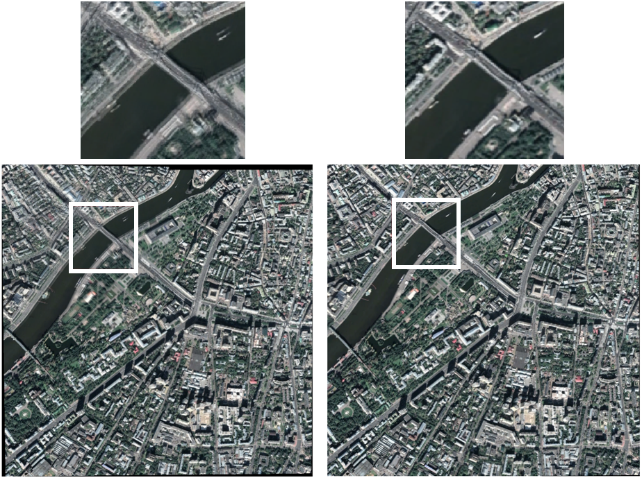
Using the methods of searching for projective transformations, one can determine the displacement of the camera position relative to the previous position in space. Under laboratory conditions, the accuracy of these data calculations is enough to build a panorama of a flat fixed object. In real conditions, when calculating the offset of the camera position relative to the previous position, a calculation error occurs (measurement error / interference / limitations imposed by algorithms, etc.). Over time, the accumulative error continues to grow in such a way that, despite the acceptable accuracy of determining the displacement between adjacent positions, the general panorama of the object will contain serious deviations (see Fig. 3).

Figure 3 - Accumulative Error
We set a goal for ourselves to develop a method for coordinating the graph of projective transformations for the task of panning flat fixed objects that is resistant to the problem of error accumulation. Another goal is to develop a method so that it does not depend on the method of calculating the parameters of the projective transformation.
One of the conditions must be met:
- shooting a fixed pseudo-object;
- filming an object close to flat from a sufficiently large distance;
- for all camera positions during shooting, the requirement is fulfilled: for all image points, the rays connecting these points with the camera focus do not coincide with each other.
Description of the algorithm for matching the graph of projective transformations
We introduce the concept of a unified coordinate system. By a single coordinate system we mean a coordinate system where the same points of the object from different images will have the same coordinates. This requirement can be expressed by the following formula:
Where - this display is defined on the common part of the frame and converts the points of the first frame to the points of the second frame, - coordinates of a point in the coordinate system of the first frame, - coordinates of a point in the coordinate system of the second frame.
When mapping can be correctly continued beyond the frame overlap area; we can supplement the second frame with information from the first. This will result in a map glued together as a mosaic from two or more frames.
After finding the projective transformations between adjacent frames, there is an initial splicing that specifies a one-to-one arrangement of frames in a single coordinate system (see Fig. 4).
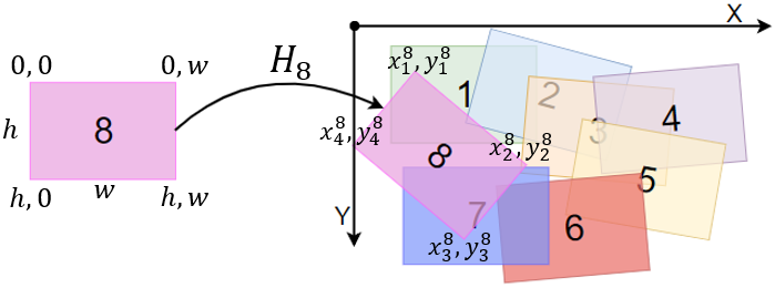
Figure 4 - The unique location of the frame on the map
After constructing the primary image splicing, a graph of projective transformations is constructed. :
Where - the set of fours of points, which are the vertices of projectively corrected images; , - many projective transformations between frames; .
The edge between the vertices is built only if the frames intersect at least on the primary gluing (IoU - Intersection over Union) (see fig. 5, 6):
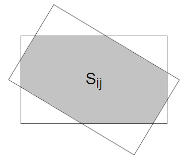
Figure 5 - The area of intersection
Threshold It is selected depending on the method used to search for a projective transformation by balancing between the conditionality of the problem of finding a projective transformation between two frames and the desired expected number of edges and cycles in the graph.
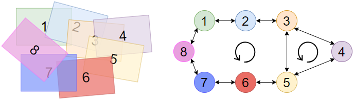
Figure 6 - Example of the construction of the graph
As a result, the graph of projective transformations looks like this (see fig. 7):
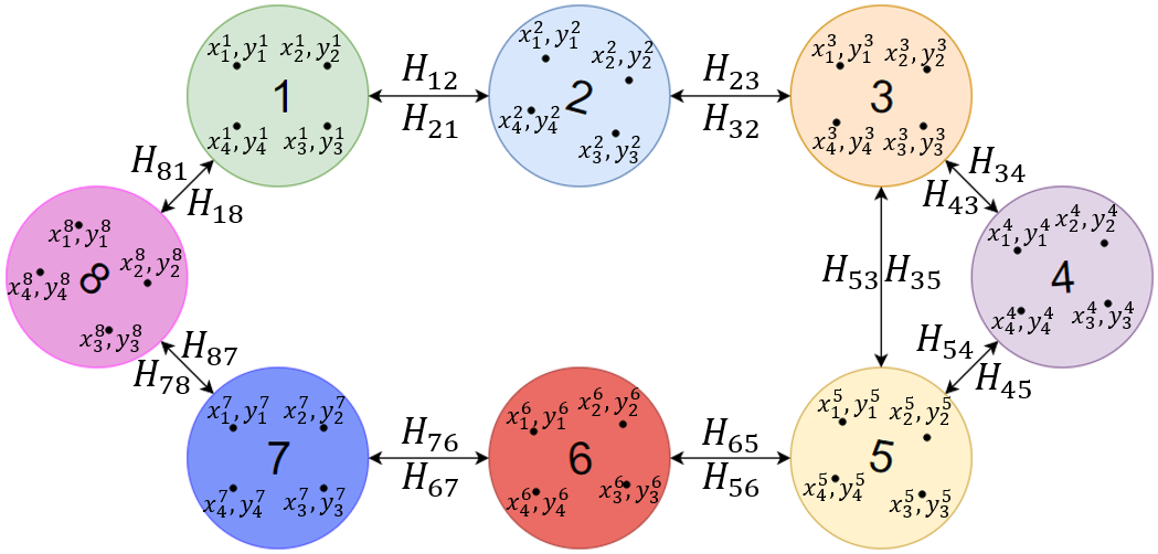
Figure 7 - The final graph of projective transformations
If the graph contains cycles (see Fig. 6), then redundant information appears in it, which may also contain contradictions. To determine what kind of contradictions may arise, consider a cycle of the graph (see Fig. 8). Let this cycle consist of vertices. Then we have a series of projective mappings along this cycle:
Consider the composition of these mappings:
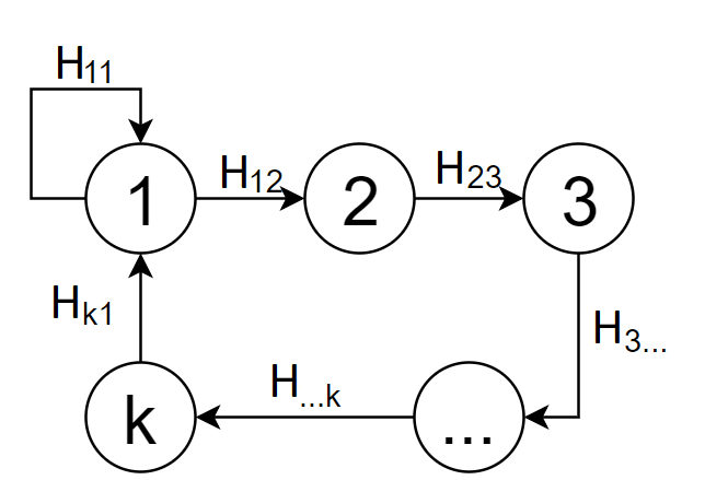
Figure 8 - The cycle of the graph
Display must be the same mapping. If the mappingdifferent from the identical, then we say that a contradiction is obtained. The cycle in this case will be called inconsistent . Thus, there is a problem associated with the presence of inconsistent cycles in the graph of projective mappings, since, with an ideal gluing together, contradictions in the graph of projective transformations must be absent.
Let us describe the algorithm for matching the graph of projective transformations, i.e., matching all its cycles. To minimize the accumulative error, which manifests itself when the cycle is closed in the graph of projective transformations, the concept of the SLAM method (Simultaneous Localization And Mapping) [9] is used.
Consider in each frame four points in general position. Let the frames be numbered from before , then the fours of points will be denoted by where . Such a set of fours of points uniquely defines a single coordinate system, since for any two frames you can uniquely find a projective mapping that translates one quadruple point to another.
To find a set of quadruple points that will define the desired consistent graph, you can use the least squares method. We minimize the functional, which is equal to the sum over all edges from the set count , and for each edge - the sum of four points of . To find a solution that minimizes the functional, it is proposed to use the conjugate gradient method.
After for each frame there is a projective transformation that uniquely specifies the position of the frame on the map, you can get an image of the panorama.
Experimental Results
To date, there is no universal method for assessing the quality of gluing images. As a rule, the quality of gluing is evaluated by experts organoleptically, but for scientific research it is preferable to have a quantitative, automatically calculated quality assessment.
In order to assess the quality of gluing without the participation of a human expert, it is necessary to have a standard gluing with which the result will be compared. The approach in which the gluing was obtained from a real video, and the standard gluing is a photograph of the entire object, requires good laboratory conditions using a manipulator that is able to physically fix (using sensors) the camera's position in space. However, this quality assessment method is costly.
In [10], in order to quantify the quality of gluing panoramas, the authors propose, having a high-resolution image, create an artificial video whose frames are projectively distorted areas of the original image (see Fig. 9). All frames, except for the first, are projectively distorted, since a single coordinate system is specified relative to the first frame. Further, these frames of artificial video are glued together in a panorama, which is further compared with the original reference image. With this approach, it is possible to avoid problems of the difference in brightness between the resulting and reference gluing, as well as the distortion of the scene.
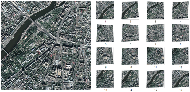
Figure 9 - Original image and frames of artificial video
To compare the quality of gluing before and after matching the graph, a test sample of 50 images was prepared; 50 artificial videos were created from the original images that were used for gluing (see Fig. 10). All the resulting panoramas were reduced to the size of the original images and for each panorama the error measure was calculated:
Where - image height, - image width, - pixel intensity obtained panorama on the red channel ( - green channel, - blue channel), - pixel intensity source image on the red channel ( - green channel, - blue channel).
Figure 10 - Panorama before the approval of the graph (RMSE = 35.3) and after (RMSE = 14.2)
In the graphical representation of the RMSE on the test sample looks as follows (see. Fig. 11):
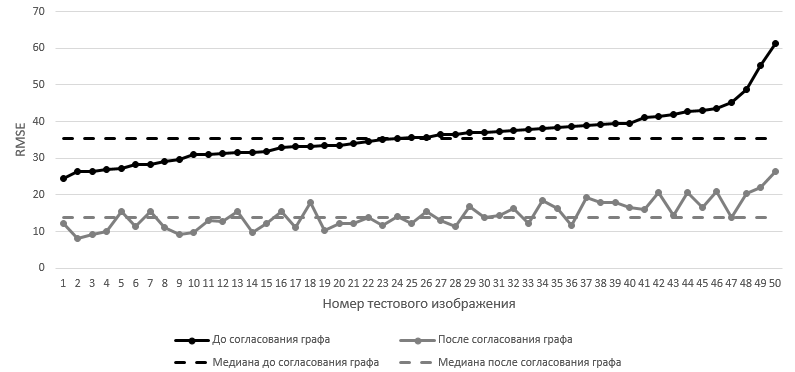
Figure 11 - RMSE on the test set. Frames are sorted in ascending order of RMSE until the graph is matched.
In accordance with each value of the root mean square error before matching, the values of the root mean square error are presented after the matching of the graph. The median RMSE value on the test sample before the graph is reconciled is 35.5 , after the graph is reconciled - 13.9 .
Conclusion
Based on the results of comparing the quality of gluing, it can be concluded that the matching of the graph significantly reduces the accumulated error and improves the quality of gluing of the panorama. However, it should be borne in mind that the coordination of the graph can only help if there are cycles in the graph of projective transformations. In the absence of cycles in the graph of projective transformations, the graph matching module does not degrade the quality of the panorama stitching.
It is worth noting that this method of matching the graph works with a set of projective transformations and the way these projective transformations were found does not matter for this method.
In the future, it is planned to optimize the complexity of the algorithm, since it is applicable only for “offline” use cases.
Literature
[1] Gubin A.Yu., Kovin R.V. A simple approach to the task of gluing overlapping images into a panorama // X International Scientific and Practical Conference of Students, Postgraduates and Young Scientists "Youth and Modern Information Technologies", p. 79-81, 2012.
[2] Drummond T., Rosten E. Machine Learning for High-Speed corner detection // 9th European Conference on Computer Vision (ECCV), p. 430-443, 2006.
[3] Lowe DG Distinctive Image Features from Scale-Invariant Keypoints // International Journal of Computer Vision, p. 91-110, 2004.
[4] Bay H., Ess A., Yuitelaars T., Van Gool L. SURF: Speeded up robust features // Computer Vision and Image Understanding, v. 110, p. 346-359, 2008.
[5] Martin A. Fischler, Robert C. Bolles. Random sample consensus: Comm. of the ACM, v. 24, p. 381-395, 1981.
[6] Arlazarov VL, Bulatov KB, Chernov TS The method of fuzzy image search in large volumes of video data // High Availability Systems, Vol. 12, No. 1, p. 53-58, 2016.
[7] N. Skoryukina et al. Snapscreen: TV-stream frame with distortion and noisy query // 9th International CO-Reference on Machine Vision (ICMV) - Proc. SPIE V. 10341, P. 103410Y, 2017.
[8] The Bouguet JY Pyramidal implementation of the affine lucas kanade feature tracker: destription of the algorithm // Intel corporation, V. 5, p. 1-10, 2001.
[9] Newman P., Ho K. SLAM-loop closing with visually salient features // IEEE Proc. of International Conference on Robotics and Automation, p. 635-642, 2005.
[10] Paalanen P., Kamarainen JK, Kalviainen H. Image based quantitative mosaic analysis with artificial video // Scandinavian Conference on Image Analysis, Springer (Berlin, Heidelberg), p. 470-479, 2009.