Nintendo DS console GPU and its interesting features
- Transfer

I would like to tell you about the operation of the Nintendo DS console GPU, its differences from modern GPUs, and also to express my opinion on why using Vulkan instead of OpenGL in emulators will not bring any advantages.
I don’t really know Vulkan, but from what I read, it’s clear that Vulkan differs from OpenGL in that it works at a lower level, allowing programmers to manage GPU memory and similar things. This can be useful for emulating more modern consoles that use proprietary graphics APIs that provide levels of control that are not available in OpenGL.
For example, the hardware renderer blargSNES - one of its tricks is that during some operations with different color buffers a single depth / stencil buffer is used. In OpenGL, this is not possible.
In addition, there is less garbage between the application and the GPU, which means that if properly implemented, the performance will be higher. While the OpenGL drivers are fully optimized for standard use cases and even for specific games, the application itself must be well written in the first place in Vulkan.
That is, in essence, “with great force comes a great responsibility.”
I'm not a 3D API expert, so back to that. what I know well: DS console GPU.
Several articles have already been written about its individual parts ( about its clever quads ,about nonsense from the viewport , about the funny features of the rasterizer and about the amazing implementation of anti-aliasing ), but in this article we will look at the device as a whole, but with all the juicy details. At least all that we know.
The GPU itself is a rather ancient and outdated hardware. It is limited to 2048 polygons and / or 6144 vertices per frame. The resolution is 256x192. Even if this is quadrupled, performance will not be a problem. Under optimal conditions, DS can output up to 1,22880 polygons per second, which is ridiculous by the standards of modern GPUs.
We now turn to the details of the GPU. On the surface, it looks quite standard, but deep down its work is very different from the work of modern GPUs, which is why emulation of some functions can be complicated.
The GPU is divided into two parts: the geometry engine and the rendering engine. The geometry engine processes the resulting vertices, builds polygons and transforms them so that you can transfer them to the rendering engine, which (you guessed it) draws everything on the screen.
Geometry Engine
Pretty standard geometric conveyor.
It is worth mentioning that all arithmetic is performed in integers with a fixed decimal point, because DS does not support floating point numbers.
The geometry engine is emulated completely programmatically (GPU3D.cpp), that is, it doesn’t really relate to what we use for rendering graphics, but I’ll still tell you in detail about it.
1. Transformations and lighting. The resulting vertices and texture coordinates are transformed using 4x4 matrix sets. In addition to the vertex colors, lighting is applied. Everything is pretty standard here, the only non-standard is how the texture coordinates work (1.0 = one Texel DS). It is also worth mentioning the whole system of matrix stacks, which are to some extent a hardware implementation of glPushMatrix ().
2. Setting polygons. Transformed vertices are assembled into polygons, which can be triangles, quadrilaterals (quads), stripes of triangles or stripes of quadrangles. Quad-s are processed natively and are not converted to triangles, which is quite problematic, because modern GPUs support only triangles. However, it seems that someonecame up with a solution that I need to test.
3. Drop. From polygons, you can get rid of depending on the focus on the screen and the selected clipping mode (culling mode). Also pretty standard layout. However, I need to figure out how this works for quad-s.
4. Truncation. Polygons outside the scope of visibility are eliminated. Polygons partially extending beyond this area are truncated. This step does not create new polygons, but adds vertices to the existing ones. In fact, each of the 6 truncation planes can add one vertex to the polygon, that is, as a result, we can have up to 10 vertices. In the section on the rendering engine, I will tell you how we dealt with it.
5. Convert to viewport. X / Y coordinates are converted to screen coordinates. Z coordinates are converted to fit in the 24-bit depth buffer interval.
It is interesting how the W coordinates are processed: they are “normalized” to fit in the 16-bit interval. For this, each W coordinate of the polygon is taken, and if it is greater than 0xFFFF, then it is shifted to the right by 4 positions to fit in 16 bits. Conversely, if the coordinate is less than 0x1000, then it moves to the left until it falls into the interval. I suppose that this is necessary for obtaining good intervals, and therefore greater accuracy in interpolation.
6. Sort. Polygons are sorted so that translucent polygons are drawn first. Then they are sorted by their Y (aha) coordinates, which is mandatory for opaque and not necessarily translucent polygons.
In addition, this is the reason for the limitation of 2048 polygons: they need to be stored somewhere to perform sorting. There are two internal memory banks allocated for storing polygons and vertices. There is even a register telling how many polygons and vertices are stored.
Rendering engine
And here the fun begins!
After all polygons have been configured and sorted, the rendering engine starts working.
The first fun moment is how it fills polygons. This is completely different from the work of modern GPUs that fill tiles and use algorithms that are optimized for triangles. I don’t know how they all work, but I’ve seen how this is done in the 3DS console GPU, and everything is based on tiles.
Be that as it may, on DS rendering is done on raster lines. Developers had to do this so that rendering could be performed in parallel with old-school two-dimensional tile engines that perform drawing on raster lines. There is a small 48 raster line buffer that can be used to correct some raster lines.
The rasterizer is a renderer of convex polygons based on raster lines. It can process an arbitrary number of vertices. It can render incorrectly if you pass to it polygons that are not convex or have intersecting edges, for example:
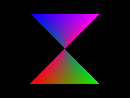
Polygon- "butterfly". All right and great.
But what if we turn it on?
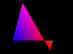
Oh.
What is the mistake here? Let's draw the outline of the source polygon to figure out:
The renderer can fill only one gap per raster line. It defines the left and right edges, starting at the highest tops, and follows these edges until it encounters new tops.
In the image shown above, it starts from the topmost top, that is, the top left, and continues to fill until it reaches the end of the left edge (bottom left top). He does not know that the edges intersect.
At this stage, he searches for the next vertex on the left edge. It is interesting to note that he knows that he does not need to take the vertices that are above the current one, and also knows that the left and right edges have changed places. Therefore, it continues to fill until the end of the polygon.
I would add some more examples of non-convex polygons, but we will deviate too much from the topic.
Let's better understand how Gouraud shading and texturing work with an arbitrary number of vertices. There are barycentric algorithms used to interpolate data on a triangle, but ... in our case, they are not suitable.
The DS renderer here also has its own implementation. Some more curious images.
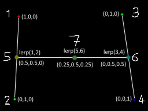
The vertices of the polygon are points 1, 2, 3, and 4. The numbers do not correspond to the present traversal order, but you understand the meaning.
In the current raster line, the renderer defines the vertices immediately surrounding the edges (as mentioned above, it starts from the topmost vertices and then passes along the edges until they are completed). In our case, these are vertices 1 and 2 for the left edge, 3 and 4 for the right edge.
The slopes of the edges are used to determine the limits of the gap, that is, points 5 and 6. At these points, the attributes of the vertices are interpolated based on the vertical positions in the edges (or horizontal positions for the edges, the slopes of which are mainly along the X axis).
Then, for each pixel in the gap (for example, for point 7), attributes based on the X position within the gap are interpolated from the attributes previously calculated at points 5 and 6.
Here, all coefficients used are 50% to simplify work, but the meaning is clear.
I will not go into the details of attribute interpolation, although it will be interesting to write about this too. In fact, this is a correct interpolation from the perspective point of view, but there are interesting simplifications and peculiarities in it.
Now let's talk about how DS fills polygons.
What rules does he use? Here, too, there are many interesting things!
First, there are different fill rules for opaque and translucent polygons. But the most important thing is that these rules apply pixel by pixel.. Translucent polygons can have opaque pixels, and they will follow the same rules as opaque polygons. One can guess that in order to emulate such tricks on modern GPUs, several rendering passes are required.
In addition, different polygon attributes can affect the rendering in various interesting ways. In addition to the fairly standard color and depth buffer , the renderer also has an attribute buffer that keeps track of all sorts of interesting things. Namely: polygon IDs (separately for opaque and translucent polygons), pixel translucency, the need to apply fog, whether this polygon is directed at or away from the camera (yes, that too), and whether the pixel is on the edge of the polygon. And maybe something else.
The task of emulating such a system will not be trivial. An ordinary modern GPU has a stencil buffer limited to 8 bits, which is far from enough for anything that can hold an attribute buffer. We need to come up with a clever workaround.
Let's see:
* depth buffer update: optional for opaque pixels, not necessarily translucent.
* Polygon IDs: polygons are assigned 6-bit IDs that can be used for several purposes. ID opaque polygons are used to mark the edges. IDs of translucent polygons can be used to control where they will be drawn: a translucent pixel will not be drawn if the polygon ID is the same as the translucent polygon ID that is already in the attribute buffer. Also, both polygon IDs are similarly used to control shadow rendering. For example, you can create a shadow covering the floor, but not the character.
(Note: shadows are just a stencil buffer implementation, there is nothing terrible here.)
It is worth noting that when rendering translucent pixels, the existing ID of an opaque polygon is preserved, as well as the flags of the edges of the last opaque polygon.
* fog flag: determines if a fog application pass needs to be performed for this pixel. The process of updating it depends on whether the incoming pixel is opaque or translucent.
* flag of the front edge: here you have problems. Look at the screenshot:
Sands of Destruction, the screens of this game are a set of tricks. They not only change their Y coordinates to affect Y-sorting. The screen shown in this screenshot is probably the worst.
It uses the boundary case of the depth test: the “less than” comparison function takes on equal values if the game draws a polygon looking into the camera over the opaque pixels of the polygon directed from the camera . Yes it is. And the Z values of all polygons are zero. If you do not emulate this feature, some elements will be missing on the screen.
I think this was done so that the front side of the object is always visible over the back side, even when they are so flat that the Z values are the same. With all these hacks and tricks, the DS renderer is similar to the hardware version of the DOS era renderers.
Anyway, it was difficult to emulate this behavior through the GPU. But there are other similar boundary cases of depth testing, which also need to be tested and documented.
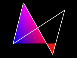
* edge flags: the renderer tracks the location of the edges of the polygons. They are used on the last aisles, namely when marking the edges and anti-aliasing. There are also special rules for filling opaque polygons with anti-aliasing disabled. The diagram below illustrates these rules:

Note: wireframe polygons are rendered by filling only edges! Very smart move.
Another fun note about depth buffering:
There are two possible depth buffering modes on DS: Z-buffering and W-buffering. It seems that it is pretty standard, but only if you do not go into details.
* Z-buffering uses Z coordinates, converted to fit in a 24-bit depth buffer interval. The Z coordinates are linearly interpolated by polygons (with some oddities, but they are not particularly important). Here, too, there is nothing non-standard.
* In W-buffering, W coordinates are used "as is". Modern GPUs usually use 1 / W, but in DS only arithmetic with a fixed comma is used, so using return values is not very convenient. However, in this mode, W coordinates are interpolated with perspective correction.
And this is what the final rendering passes look like:
* edge marking: for pixels that have edge flags set, a color is taken from the table and determined based on the opaque polygon ID.
They will be colored edges of polygons. It is worth noting that if a translucent polygon is drawn on top of an opaque polygon, the edges of the polygon will still be colored.
A side effect of the principle of truncation: the boundaries in which polygons intersect with the boundaries of the screen will also be colored. You can for example notice this in the Picross 3D screenshots.
* fog: it is applied to each pixel based on the depth values used to index the fog density table. As you can guess, it applies to those pixels that set the fog flags in the attribute buffer.
* anti-aliasing (anti-aliasing): it is applied to the edges of (opaque) polygons. Based on the slopes of the edges, when rendering polygons, the pixel coverage values are calculated. On the last pass, these pixels are mixed with the pixels under them using a tricky mechanism, which I described in a previous post.
Antialiasing should not (and cannot) be emulated in this way on the GPU, so this is not important here.
Except that if edge marking and anti-aliasing should be applied to the same pixels, they get only the size of the edges, but with 50% opacity.
It seems that I have described the rendering process more or less well. We did not go deep into the mixing of textures (a combination of vertex colors and textures), but it can be emulated in a fragment shader. The same applies to edge markings and fog, provided that we find a way around the entire system with an attribute buffer.
But in general, I wanted to bring the following: OpenGL or Vulkan (as well as Direct3D, or Glide, or anything else) will not help here. Our modern GPUs have more than enough power to work with raw polygons. The problem lies in the details and features of rasterization. And it's not even a matter of pixel ideality, it's enough to look at the issue tracker of the DeSmuME emulator for an example, in order to understand what problems developers encounter when rendering via OpenGL. With the same problems, we also have to somehow cope.
Also note that using OpenGL will allow you to port the emulator, let's say on the Switch (because the Github user named Hydr8gon started creating the port of our emulator on the Switch ).
So ... wish me luck.