Pulse power supply for teletype from the 1940s (with luminous mercury thyratrons!)
- Transfer
Recently, we began the process of restoring the teletype Model 19, a naval communications system from the 1940s [1] .This teletype was powered by a massive DC power supply unit called Rectifier REC-30. It used special thyratrons on mercury vapor, which gave an eerie blue glow when turned on, as in the photo below.

The thyratron tubes in the REC-30 power supply give out such a blue glow. Orange light comes from a neon lamp used as a reference voltage source.
The REC-30 is an interesting specimen primarily because it is a very early switching power supply. (I know that it’s quite controversial to call this device a pulse power supply, but, nevertheless, I don’t see a good reason for not doing this). Despite the fact that in our days, switching power supplies are used everywhere (because of the cheapness of high-voltage transistors), they were a wonder in the 1940s. REC-30 is huge - its weight exceeds 45 kilograms! If you compare it with 300 grams of power supply for a MacBook, you can see impressive progress in the development of power supplies since the 1940s. In this post I will look inside the power supply, describe its principles of operation, and compare it with the power supply for MacBook.

Teletype Model 19. Image from the magazine BuShips Electron from 1945.
Teletype is a brand of the manufacturer of teleprinters, which, in fact, are typewriters that can communicate through a wired connection over long distances. You may be familiar with teletypes through old films about journalism, in which these devices are used to broadcast newsletters. Or maybe you saw computers from the 1970s with an ASR33 teletype as a terminal. Most of the terminology for serial port technology in modern computers comes from the teletype era: start and stop bits, heart rate, TTY, and even the Break key. Teletypes also knew how to write and read characters from punched tapes using 5-bit encoding [2] .
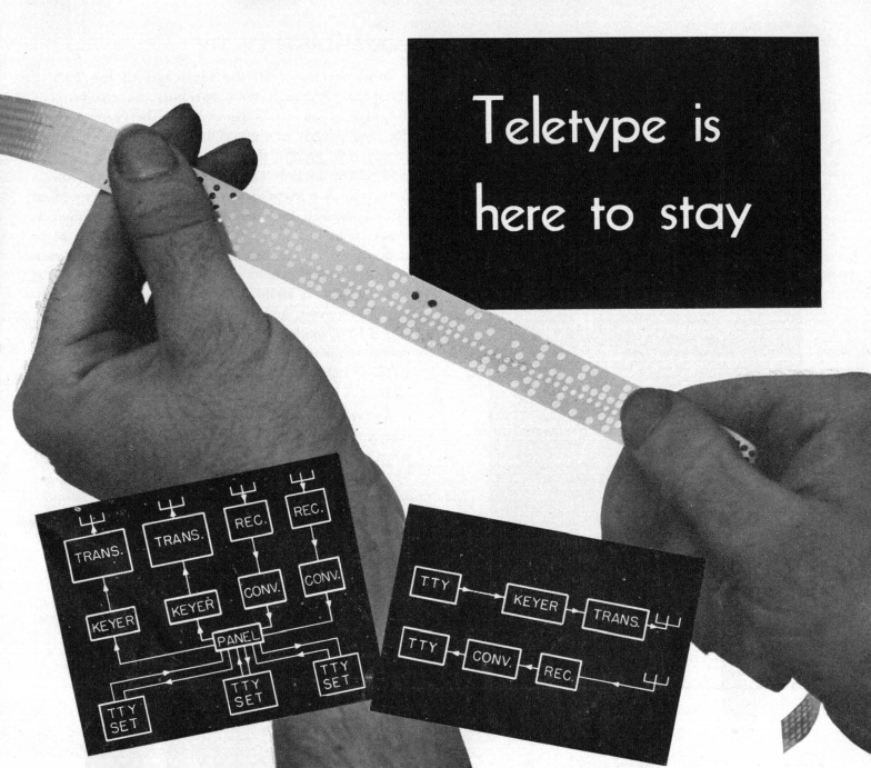
"The teletype will remain forever." The photo shows punched tape for 5-bit coding used by teletype. Image from the magazine BuShips Electron from 1945.
Teletypes appeared in the early 1900s. In this pre-electronic era, symbol selection, serialization, and printing were achieved through the use of complex electromechanical devices: electromagnets, switches, levers, gears, and cam mechanisms. Pressing a key in the teletype closes a specific set of switches associated with the symbol. The motorized distributor serialized this set of bits for transmission over the wire. On the receiving side, electromagnets transformed the received data bits into movements of mechanical selective ridges. The movement of the ridges forms a combination of grooves corresponding to the adopted symbol and coincides with the typical lever associated with the sign. As a result, we get the typed character [3] .
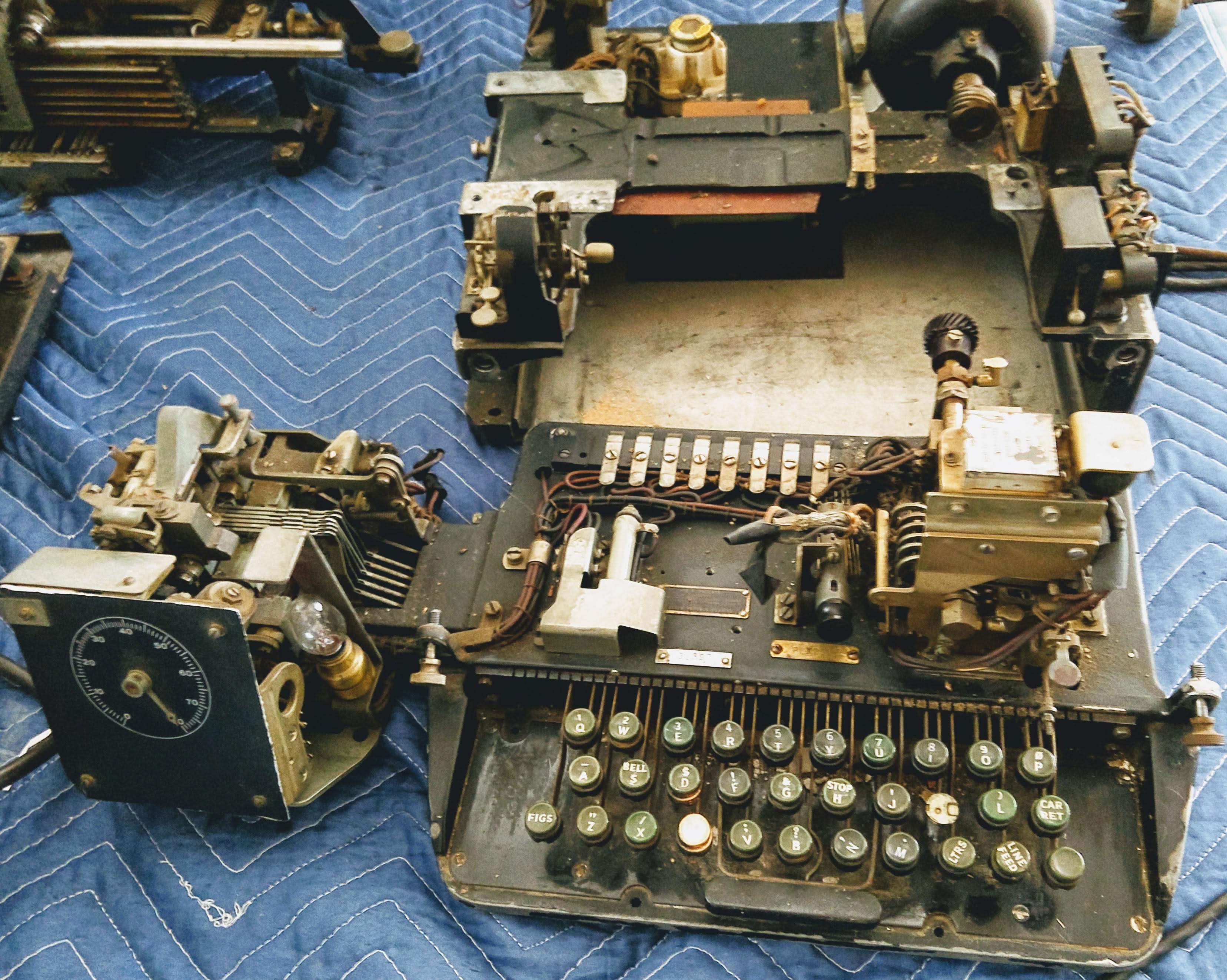
Partially Disassembled Teletype Model 19
Teletypes communicate with each other through a 60mA current loop: the presence of current in the circuit gives the value "marker" (teletype, respectively, perforates punched tape), and if the current is interrupted, then we get a value called "space". Each character is transmitted in seven bits: the start bit, 5 data bits and the stop bit. If you have ever used serial devices on your PC, then you should know that teletypes introduced the notions of start and stop bits. A bodrate was named after the inventor of 5-bit coding - Emile Bodo . The REC-30 power supply delivered 900 mA at 120V DC, enough to power 15 teletypes.
Perhaps you are wondering why teletypes simply did not use voltage levels instead of this strange current loop? The main reason is that when sending signals by wire to another city, it is very difficult to know what the final voltage will be at the other end, due to the voltage drop along the way. But if you send 60mA, the receiver will receive the same 60mA (if there is no short circuit, of course) [4] .A large current is needed in order to set in motion the electromagnets and relays in teletypes. In the future, teletypes began to more often use a 20mA current loop instead of 60mA.
There are several ways to develop a stabilizing power source. The simplest and most obvious is the linear power supply, which is built on lamps or transistors to stabilize the voltage. The power supply behaves as a variable resistor, lowering the input voltage to the required output level. The problem with linear power supplies is that, in principle, they are not very effective, because the excess voltage is converted into useless heat.
Indeed, more modern power supplies are pulsed. They turn on and off with high frequency, thus bringing the average voltage to the desired output level. Since the switching element (no matter whether it is active or not) does not have such a high resistance as a linear power source, the impulse units spend very little energy for nothing. In addition, they are usually much smaller and lighter, but, obviously, the REC-30 developers did not follow this canon (its width is more than 60 cm) [5]. Most power supplies that you come across are pulsed - from charging for the phone to the power supply of your computer. Pulsed PSUs gained their popularity in the 1970s after the development of high-voltage semiconductors, so REC-30, with its lamp component base, is a very unusual instance.
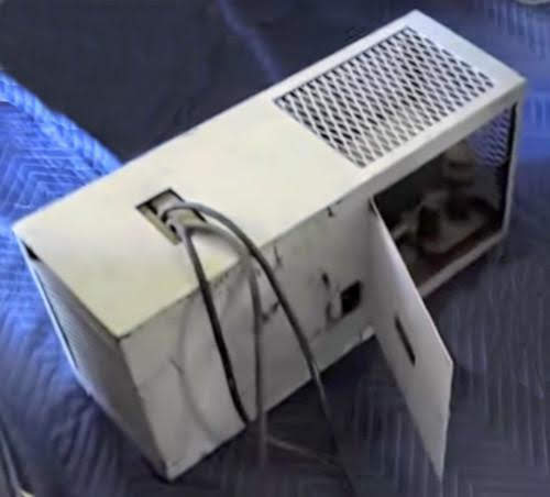
The TTY power supply unit REC-30 in its gray colored case. Power cables extend from the top. Lamps are located behind the door on the right.
In the photo below you can see the main components of the power supply. Alternating current is fed to the left and fed into a large autotransformer . The autotransformer is a special single-winding multipurpose transformer that converts the input AC voltage (which can be from 95V to 250V) [6]at a fixed 230V. Due to this, the power supply is able to digest a wide range of input voltages, by simply connecting the wire to the corresponding terminal of the autotransformer. Output 230V from the autotransformer are fed to the anode transformer (control), which produces 400V for thyratron tubes [7] .They, in turn, straighten and stabilize the voltage, turning the alternating current into direct current. Then the current is filtered by capacitors (they are not visible in the photo) and inductors (chokes) and finally 120 V DC is obtained at the output.
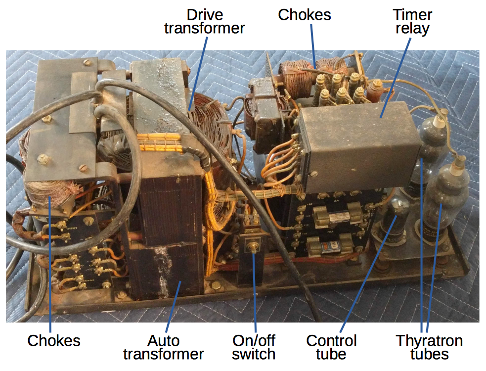
Main components of the REC-30
Omit until the power switch itself. AC-to-DC conversion to REC-30 takes place through the use of a full-wave rectifier and a medium-point transformer (control transformer), much like the diagram below (instead of diodes, current-rectifier tubes use thyratron tubes). The transformer windings produce two sine waves in antiphase, so we always have a positive current phase that we pass through one of the thyratron tubes, receiving a pulsating direct current (in other words, the negative AC phase is inverted and a positive output signal is obtained). Then the power supply, with the help of inductors (chokes) and filter capacitors, smoothes the ripple and provides an even voltage at the output.
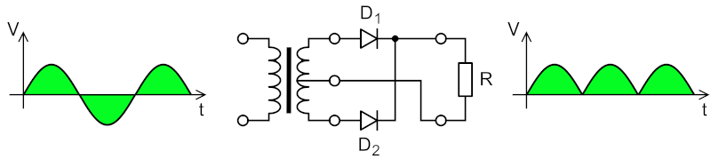
A full-wave rectifier circuit (center) that converts alternating current (left) into a pulsating constant (right). Image by Wdwd , CC BY 3.0 .
Unlike the diodes in the diagram above, the thyratron tubes in the power supply can be turned on and off, thus giving you the ability to control the output voltage. The basic idea is to include the thyratron in a certain fixed phase of the alternating current cycle, as in the animation below. If the thyratron is on a full cycle, then we get the full voltage, if the half-cycle is on, then half the voltage, and if only for a small fraction of the cycle, then the output will be very small voltage [8] .This technique is called phase control , because the device is turned on only at a certain phase angle (for example, between 0 ° and 180 ° for an AC sinusoid). A very similar method is used in conventional dimmer lighting , except that they use semiconductor triacs instead of thyratron tubes [9].
Phase regulation scheme. The upper part of the animation shows what part of the pulse is used, and the lower one shows the moment in which the thyratron is on. Image copyright by Zureks , CC BY-SA 2.5 .
The thyratron tubes of the power unit resemble radio tubes, but unlike them, they contain argon and mercury vapors inside a glass bulb (whereas vacuum tubes are maintained in radio tubes). Thyratron tubes consist of three components: the filament (cathode), the anode and the grid. Incandescent filament, similar to those used in conventional light bulbs, heats up and emits electrons. The anode, attached to the top of the tube, captures these electrons, thus allowing current to flow from the cathode to the anode. The reference electrode (grid) located between the anode and the cathode serves the purpose of blocking the flow of electrons. When electrons flow to the anode, the mercury vapor ionizes, thus opening the thyratron and producing a side effect in the form of a blue glow, which you can see in the photo (but in conventional radio tubes, although there is a stream of electrons, but nothing to ionize). Ionized mercury creates a highly conductive path between the cathode and the anode, allowing a fairly strong current to flow (1.5A). Once the mercury is ionized, the grid no longer controls the thyratron, and it remains open until the voltage between the anode and cathode drops to zero. At this point, the ionization drops and the tube turns off until it is again in the open state.
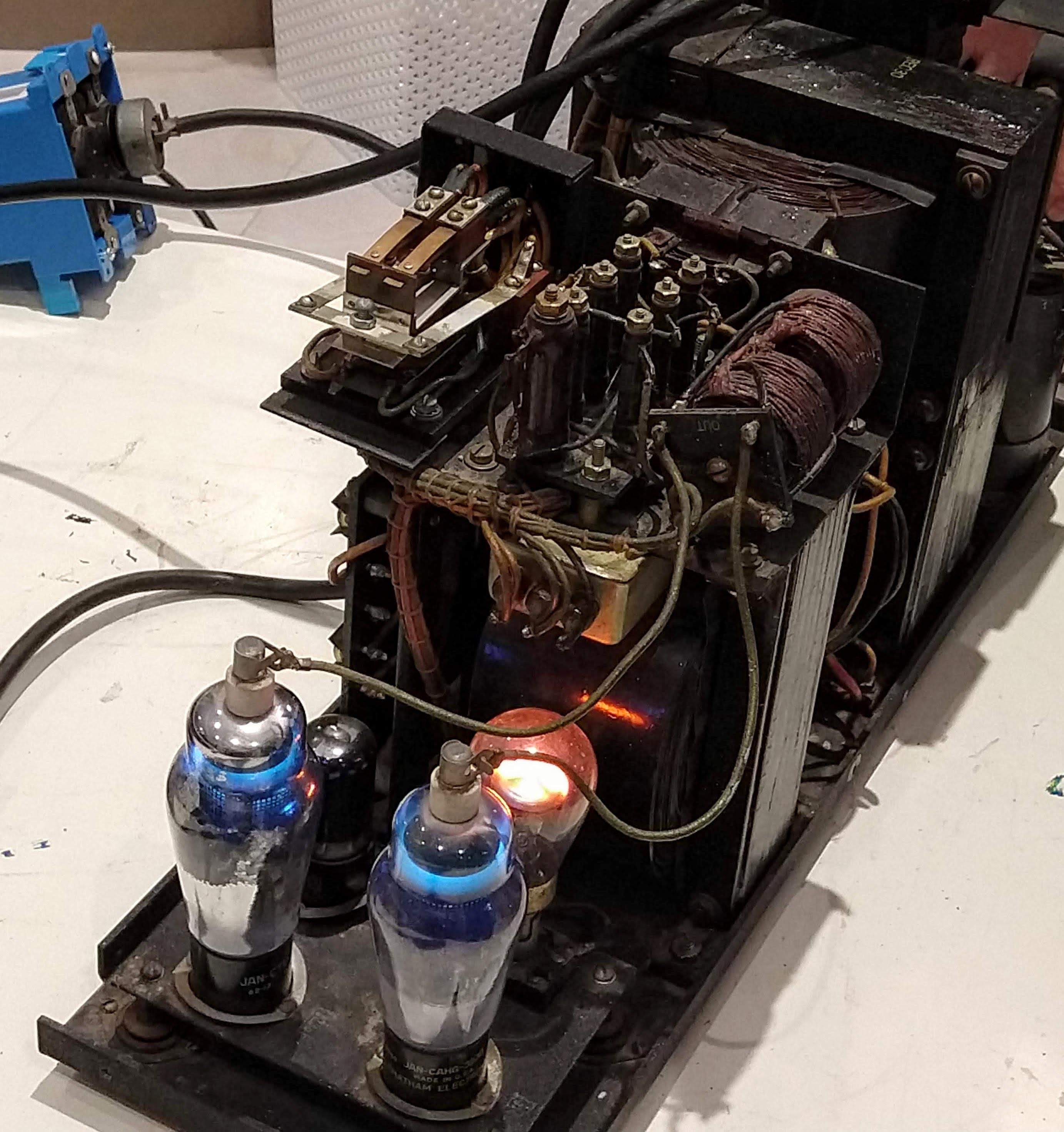
REC-30 power pack for teletype. The blue luminescence of the thyratron tubes is visible; the orange luminescence of the neon lamp used as a source of reference voltage. The timer and the relay are noticeable from the left above.
The voltage on the grid is controlled by a tiratron. Negative voltage reflects negatively charged electrons, thus preventing electrons from flowing between the cathode and the anode. But when the voltage at the anode becomes strong enough, the electrons overcome the repulsion of the grid, and the thyratron opens. The important point is that the higher the negative voltage on the grid, the stronger the repulsion occurs and the higher voltage is required to open the thyratron. Thus, the grid voltage controls the phase of the alternating current cycle in which the thyratron opens.
The power supply control circuit stabilizes the output voltage by changing the voltage on the grid, controlling the timings of the thyratron [10]. I used the power supply adjustment potentiometer to show how the voltage changes when the timings change. I managed to set the output voltage (blue on the oscillogram) in the range from 114V to 170V. The stabilizing circuit regulated the grid voltage (pink), and through it controlling the timings of the thyratrons (blue-green and yellow) [11]. The oscillogram is a little tricky - pay attention to the corresponding note.. The main detail that is important to notice is how the peaks of the blue-green and yellow curves shift to the left with increasing output voltage, and this means that the thyratrons work out earlier.
By changing the phase, the output voltage is regulated from 130V to 170V. Yellow and blue-green are the voltages on the thyratrons. Pink - control grid signal. Blue - inverted output voltage.
The image below shows the schematic of the power supply module REC-30 (larger - here). The AC input circuit is green. In it, the autotransformer stabilizes the input voltage to 230V and supplies it to the control transformer. Installed thyratron tubes have an interesting feature - they must be preheated before use to ensure that the mercury is in a gaseous state. Warming up is performed by using a bimetallic timer for 20 seconds [13]. The secondary side of the control transformer, which produces 400V voltage, is marked in red, the voltage stabilized by tiratrons is highlighted in orange, and the low voltage - in blue [14]. The control circuit (bottom of the circuit) is a bit more complicated. The control grid lamp (pentode 6J6) provides the control voltage to the thyratron grids, controlling when they should be turned on. This lamp accepts feedback voltage (pin 5) via a potentiometer (using voltage division). The output contact of the lamp (pin 3) sets the voltage of the thyratron grid and thus keeps the output voltage stable. The voltage drop across the neon lamp is almost constant, which allows it to behave as a reference voltage source and output a fixed voltage to the cathode of the control lamp (pin 8)
. REC-30 power supply circuit. For some unknown reason, in the drawing, Ohms are labeled with lowercase omega (ω) instead of the usual Ω
It is interesting to compare this power supply with a modern power supply for the MacBook in order to trace how strongly the power supply has evolved over the past 70 years. The power adapter for the Apple MacBook is more or less comparable to the REC-30 power supply: it produces 85W of DC, converting the input variable (in the REC-30, this figure is 108 watts). However, the MacBook's power supply weighs about 280 grams, while the REC-30 weighs about 45 kilograms. In addition, the size is also significantly less than even 1% of the dimensions of the REC-30, which clearly shows the incredible success in the miniaturization of electronics since the 1940s. Massive thyratrons for power switching were replaced by compact MOSFETs. Resistors have gone from finger sizes to sizes smaller than a grain of rice. Modern capacitors have become smaller
Inside the 85-watt power supply for the Apple MacBook. Despite its small size, the power supply is much more complex compared to the REC-30. It has a power factor correction circuit (PFC) to improve the efficiency of the power line. Numerous security functions (for the sake of which there is even a 16-bit microcontroller in the circuit!) Track the status of the power supply and turn it off in case of any threat or error.
Most of the weight of the MacBook's charger was dropped by replacing a huge autotransformer and anode control transformer with small high-frequency transformers. A MacBook's power supply operates at frequencies 1000 times larger than REC-30, which allows inductors and transformers to be much smaller. (I wrote a more detailed article about charging the MacBook here , and about the history of power supplies here .)
In the table below I summarized the differences between the REC-30 and the power supply of the MacBook.
I measured the quality of the REC-30 output signal (in the image below). The power supply produces a much higher quality signal than I expected - a pulsation of only 200 mV (waves on the blue horizontal line), which is very close to the level of Apple devices. However, the oscillogram also shows narrow bursts (vertical lines) of about 8 volts, which occur when switching thyratrons. These bursts are very large compared to the power supply from Apple, but still much less than in cheap chargers .
The output signal of the power supply REC-30. You can see a slight ripple and surges when switching power.
The REC-30 power supply delivers over 100 watts of DC power for a teletype. Released in the 1940s, the REC-30 was an extremely early switching power supply using mercury thyratron tubes for greater efficiency. It was monstrously large for a 100W power supply: the weight was more than 45 kilograms. A comparable modern power unit is smaller and lighter by more than 100 times. Despite its age, the power supply worked flawlessly, as you can see in Mark's video. In addition, the work process itself looks very nice - the blue glow from the tiratrons and the orange from the large neon lamp.
Thanks to Carl Claunch and Marc Verdiell for their work with this power supply!
1. The first mention of the introduction of teletypes for the Navy was in the magazine BuShips Electron from September 1945. The development of a radioteletype (RTTY), in which frequency manipulation (FSK) is commonly used, allowed the use of teletypes for the needs of the Navy. At first, the fleet used radioteletayps only for communication between coastal stations between themselves, and only then began to use them on ships. The key advantage of the teletype was speed: it was four times faster than sending a message by radio by an operator manually. In addition, messages on punched tape could be automatically copied and forwarded. Also , the teletype could be integrated with cryptographic equipment, such as SIGTOT , based on a cryptosystem of disposable notebooks. You can read more about WWII teletypes.here . ↑
2. In the 1870s, Emile Bodo invented a 5-bit code named after him. Another 5-bit code was created by Donald Murray in 1901 and was standardized as ITA-2 (CCITT-2). Both coding schemes look haphazard - the characters appear scattered in random order. However, the original Bodo code was also the Gray code, and Murray's code was optimized to make fewer perforations for the most common symbols, which allowed reducing the wear of mechanisms. 5-bit codes were relevant before ASCII standardization in the 1960s, in which the alphabetic and binary order of the characters are the same. ↑
3. More detailed information on how the teletype works - here . In addition, there is an even more extensive document - Fundamentals of Telegraphy (Teletypewriter) , Army Technical Manual TM 11-655, 1954. The drawings on the REC-30 can be downloaded from here , and the documentation here . ↑
4. Note that, in contrast to a system based on voltage measurement, the components of the current loop, as the name implies, must form a topological loop in order for current to flow through them. If you exclude any device from the chain, then the loop will break if there is no loop closing mechanism. As a result, the teletype communication system contains many sockets that close when the component is disconnected in order for the current loop to continue to function. ↑
5. The main reason that the REC-30 is so large and heavy, compared to modern switching power supplies, is that the pulse frequency is only 60 Hz, while modern power supplies operate at a frequency of tens of kilohertz. Since the EMF of a transformer is proportional to the frequency of its operation, high-frequency transformers can be much smaller in size than low-frequency ones ( more ). ↑
6. REC-30 can operate with a wide range of input voltages (95, 105, 115, 125, 190, 210, 230, 250 volts AC) and currents of various frequencies (25, 40, 50 and 60 Hz). Modern pulse power supplies automatically adjust to the input voltage, but the REC-30 requires connecting the contact to the corresponding terminal of the autotransformer to change the input voltage. You might find the 25Hz frequency very strange for the input current of the power supply, but many US regions used 25 Hz power in the 1900s. In particular, Niagara Falls generated an electric current of 25 Hz due to the design features of the turbines. In 1919, more than 2/3 of the energy output in New York was at a frequency of 25 Hz, and in Buffalo it was only in 1952 that they began to use a 60 Hz current in large volumes than 25 Hz.more ). ↑
7. Isolating input AC from output DC is a key safety element in most power supplies, including chargers, computer power supplies, and the considered REC-30. This decoupling prevents strong electric shock in contact with the output contacts. For REC-30, the anode transformer plays a critical role as an insulator. Note that the autotransformer does not provide any insulation protection, since it has only one main winding and to touch its output is the same as touching the AC input current. The rest of the circuit is carefully designed so that there is no direct path between the input and the output: the control system is entirely on the secondary side, the filaments of the thyratrons are fed from the winding, isolated from the autotransformer, and relays provide isolation to the timer. In addition, the 120V output is made push-pull instead of grounding one of the contacts: this means that you need to grab 2 contacts at once to get an electric shock.↑
8. Modern pulse power supplies use pulse-width modulated (PWM) circuits to switch power at a frequency of thousands of times per second. This allows them to have a much smaller size and a smoother output than the power supplies, which switch only once in one AC cycle. But at the same time, they need a much more complex management system. ↑
9. The current solid-state equivalent of tiratrons is a silicon rectifier , which is also called SCR or thyristor (a combination of the words "tiratron" and "transistor"). SCR has four semiconductor layers (compared to a 2-layer diode and a 3-layer transistor). Just like the thyratron, the SCR is in the off state until current is applied to the control electrode. The SCR remains on and acts as a diode until the voltage drops to 0 (strictly speaking, until the flowing current becomes less than the holding current). A triac is a semiconductor element, very similar to SCR, except that it transmits current in both directions, which makes it more convenient in alternating current circuits. ↑
10. Initially, I thought that, with increasing load, the thyratrons would be open for longer periods of time in order to provide more current. However, after connecting the oscilloscope and studying the behavior of the thyratrons under different loads, I did not notice any phase shift. It turned out that this is the expected behavior: the transformer produces in general a constant voltage, regardless of the load. Thus, the timings of the thyratrons remain constant with changes in the load, and the transformer simply produces more current. In this video you can see how the luminescence of the thyratrons changes with increasing current strength. ↑
11. Under a light load, the power supply may even occasionally skip the AC cycle completely, instead of switching the thyratrons in between. Visually, this can be seen as the flickering of tiratrons, instead of a constant glow. Not sure if it's a bug or a feature. ↑
12. On the oscillogram, the yellow and blue-green lines indicate the voltage on two thyratrons. The flat part of the lines (at this moment the difference in voltages is near zero) means that at this moment the thyratron is turned on. Thyratron tubes are asymmetrical, and therefore the one to which the yellow signal is fixed usually switches on later (visually, one thyratron glows brighter than the other). The pink line is the voltage of the control grid. Note that it increases in order to increase the output voltage, and this increase causes the thyratrons to operate earlier. The vertical splash of the pink line is just noise due to the triggering of thyratrons. The blue line below is the output voltage (inverted: the line goes down as the voltage rises).
For me, the mystery is why always at least one thyratron works - constantly either the yellow or blue-green lines are at zero. I would expect to see a gap between zero voltage on one thyratron and the moment of opening the second. I suspect that large inductors induce a negative charge on the cathode, thus, even when the anode itself is negative, the potential difference between the cathode and the anode is still positive. ↑
13. A 20-second delay before powering the tubes is achieved by a timer and a relay. The timer uses a bimetal plate with a preheater. When you turn on the power supply, the cathode receives power immediately
to warm up the tubes. At the same time, the heater inside the timer heats the bimetallic plate and at some point the plate bends enough to close the contacts and power the tubes. At the same time, the relay is activated and in turn also closes the contacts. ↑
14. The cathode-related circuit is a bit tricky, since the filaments of the thyratrons are used both as heating tubes and directly as cathodes. They are fed 2.5V from the autotransformer. In addition, since the filaments in the thyratrons of the filament are also cathodes, they themselves produce an output voltage and are connected to the high side of the output signal. In order to ensure the fulfillment of both tasks, the split winding of the autotransformer imposes a voltage of 2.5V on the filament, but at the same time passes the output voltage directly. Both thyratrons use a total of 35W on the filament only, so that, as you can see, heating spends a lot of energy and generates a lot of heat, and thus, in some way, negates the benefits of a switching power supply. ↑
The thyratron tubes in the REC-30 power supply give out such a blue glow. Orange light comes from a neon lamp used as a reference voltage source.
The REC-30 is an interesting specimen primarily because it is a very early switching power supply. (I know that it’s quite controversial to call this device a pulse power supply, but, nevertheless, I don’t see a good reason for not doing this). Despite the fact that in our days, switching power supplies are used everywhere (because of the cheapness of high-voltage transistors), they were a wonder in the 1940s. REC-30 is huge - its weight exceeds 45 kilograms! If you compare it with 300 grams of power supply for a MacBook, you can see impressive progress in the development of power supplies since the 1940s. In this post I will look inside the power supply, describe its principles of operation, and compare it with the power supply for MacBook.
What is a teletype?
Teletype Model 19. Image from the magazine BuShips Electron from 1945.
Teletype is a brand of the manufacturer of teleprinters, which, in fact, are typewriters that can communicate through a wired connection over long distances. You may be familiar with teletypes through old films about journalism, in which these devices are used to broadcast newsletters. Or maybe you saw computers from the 1970s with an ASR33 teletype as a terminal. Most of the terminology for serial port technology in modern computers comes from the teletype era: start and stop bits, heart rate, TTY, and even the Break key. Teletypes also knew how to write and read characters from punched tapes using 5-bit encoding [2] .
"The teletype will remain forever." The photo shows punched tape for 5-bit coding used by teletype. Image from the magazine BuShips Electron from 1945.
Teletypes appeared in the early 1900s. In this pre-electronic era, symbol selection, serialization, and printing were achieved through the use of complex electromechanical devices: electromagnets, switches, levers, gears, and cam mechanisms. Pressing a key in the teletype closes a specific set of switches associated with the symbol. The motorized distributor serialized this set of bits for transmission over the wire. On the receiving side, electromagnets transformed the received data bits into movements of mechanical selective ridges. The movement of the ridges forms a combination of grooves corresponding to the adopted symbol and coincides with the typical lever associated with the sign. As a result, we get the typed character [3] .
Partially Disassembled Teletype Model 19
Current loop
Teletypes communicate with each other through a 60mA current loop: the presence of current in the circuit gives the value "marker" (teletype, respectively, perforates punched tape), and if the current is interrupted, then we get a value called "space". Each character is transmitted in seven bits: the start bit, 5 data bits and the stop bit. If you have ever used serial devices on your PC, then you should know that teletypes introduced the notions of start and stop bits. A bodrate was named after the inventor of 5-bit coding - Emile Bodo . The REC-30 power supply delivered 900 mA at 120V DC, enough to power 15 teletypes.
Perhaps you are wondering why teletypes simply did not use voltage levels instead of this strange current loop? The main reason is that when sending signals by wire to another city, it is very difficult to know what the final voltage will be at the other end, due to the voltage drop along the way. But if you send 60mA, the receiver will receive the same 60mA (if there is no short circuit, of course) [4] .A large current is needed in order to set in motion the electromagnets and relays in teletypes. In the future, teletypes began to more often use a 20mA current loop instead of 60mA.
Why use a switching power supply?
There are several ways to develop a stabilizing power source. The simplest and most obvious is the linear power supply, which is built on lamps or transistors to stabilize the voltage. The power supply behaves as a variable resistor, lowering the input voltage to the required output level. The problem with linear power supplies is that, in principle, they are not very effective, because the excess voltage is converted into useless heat.
Indeed, more modern power supplies are pulsed. They turn on and off with high frequency, thus bringing the average voltage to the desired output level. Since the switching element (no matter whether it is active or not) does not have such a high resistance as a linear power source, the impulse units spend very little energy for nothing. In addition, they are usually much smaller and lighter, but, obviously, the REC-30 developers did not follow this canon (its width is more than 60 cm) [5]. Most power supplies that you come across are pulsed - from charging for the phone to the power supply of your computer. Pulsed PSUs gained their popularity in the 1970s after the development of high-voltage semiconductors, so REC-30, with its lamp component base, is a very unusual instance.
The TTY power supply unit REC-30 in its gray colored case. Power cables extend from the top. Lamps are located behind the door on the right.
Inside the power supply REC-30
In the photo below you can see the main components of the power supply. Alternating current is fed to the left and fed into a large autotransformer . The autotransformer is a special single-winding multipurpose transformer that converts the input AC voltage (which can be from 95V to 250V) [6]at a fixed 230V. Due to this, the power supply is able to digest a wide range of input voltages, by simply connecting the wire to the corresponding terminal of the autotransformer. Output 230V from the autotransformer are fed to the anode transformer (control), which produces 400V for thyratron tubes [7] .They, in turn, straighten and stabilize the voltage, turning the alternating current into direct current. Then the current is filtered by capacitors (they are not visible in the photo) and inductors (chokes) and finally 120 V DC is obtained at the output.
Main components of the REC-30
Omit until the power switch itself. AC-to-DC conversion to REC-30 takes place through the use of a full-wave rectifier and a medium-point transformer (control transformer), much like the diagram below (instead of diodes, current-rectifier tubes use thyratron tubes). The transformer windings produce two sine waves in antiphase, so we always have a positive current phase that we pass through one of the thyratron tubes, receiving a pulsating direct current (in other words, the negative AC phase is inverted and a positive output signal is obtained). Then the power supply, with the help of inductors (chokes) and filter capacitors, smoothes the ripple and provides an even voltage at the output.
A full-wave rectifier circuit (center) that converts alternating current (left) into a pulsating constant (right). Image by Wdwd , CC BY 3.0 .
Unlike the diodes in the diagram above, the thyratron tubes in the power supply can be turned on and off, thus giving you the ability to control the output voltage. The basic idea is to include the thyratron in a certain fixed phase of the alternating current cycle, as in the animation below. If the thyratron is on a full cycle, then we get the full voltage, if the half-cycle is on, then half the voltage, and if only for a small fraction of the cycle, then the output will be very small voltage [8] .This technique is called phase control , because the device is turned on only at a certain phase angle (for example, between 0 ° and 180 ° for an AC sinusoid). A very similar method is used in conventional dimmer lighting , except that they use semiconductor triacs instead of thyratron tubes [9].
Phase regulation scheme. The upper part of the animation shows what part of the pulse is used, and the lower one shows the moment in which the thyratron is on. Image copyright by Zureks , CC BY-SA 2.5 .
The thyratron tubes of the power unit resemble radio tubes, but unlike them, they contain argon and mercury vapors inside a glass bulb (whereas vacuum tubes are maintained in radio tubes). Thyratron tubes consist of three components: the filament (cathode), the anode and the grid. Incandescent filament, similar to those used in conventional light bulbs, heats up and emits electrons. The anode, attached to the top of the tube, captures these electrons, thus allowing current to flow from the cathode to the anode. The reference electrode (grid) located between the anode and the cathode serves the purpose of blocking the flow of electrons. When electrons flow to the anode, the mercury vapor ionizes, thus opening the thyratron and producing a side effect in the form of a blue glow, which you can see in the photo (but in conventional radio tubes, although there is a stream of electrons, but nothing to ionize). Ionized mercury creates a highly conductive path between the cathode and the anode, allowing a fairly strong current to flow (1.5A). Once the mercury is ionized, the grid no longer controls the thyratron, and it remains open until the voltage between the anode and cathode drops to zero. At this point, the ionization drops and the tube turns off until it is again in the open state.
REC-30 power pack for teletype. The blue luminescence of the thyratron tubes is visible; the orange luminescence of the neon lamp used as a source of reference voltage. The timer and the relay are noticeable from the left above.
The voltage on the grid is controlled by a tiratron. Negative voltage reflects negatively charged electrons, thus preventing electrons from flowing between the cathode and the anode. But when the voltage at the anode becomes strong enough, the electrons overcome the repulsion of the grid, and the thyratron opens. The important point is that the higher the negative voltage on the grid, the stronger the repulsion occurs and the higher voltage is required to open the thyratron. Thus, the grid voltage controls the phase of the alternating current cycle in which the thyratron opens.
The power supply control circuit stabilizes the output voltage by changing the voltage on the grid, controlling the timings of the thyratron [10]. I used the power supply adjustment potentiometer to show how the voltage changes when the timings change. I managed to set the output voltage (blue on the oscillogram) in the range from 114V to 170V. The stabilizing circuit regulated the grid voltage (pink), and through it controlling the timings of the thyratrons (blue-green and yellow) [11]. The oscillogram is a little tricky - pay attention to the corresponding note.. The main detail that is important to notice is how the peaks of the blue-green and yellow curves shift to the left with increasing output voltage, and this means that the thyratrons work out earlier.
By changing the phase, the output voltage is regulated from 130V to 170V. Yellow and blue-green are the voltages on the thyratrons. Pink - control grid signal. Blue - inverted output voltage.
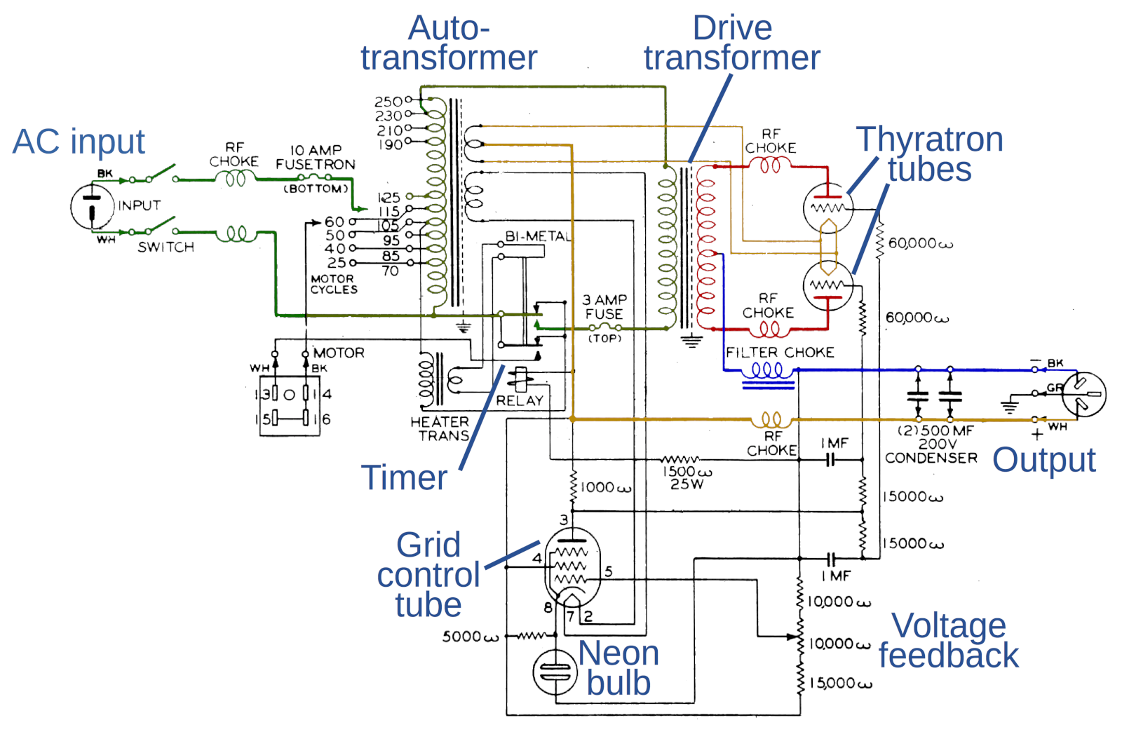
The image below shows the schematic of the power supply module REC-30 (larger - here). The AC input circuit is green. In it, the autotransformer stabilizes the input voltage to 230V and supplies it to the control transformer. Installed thyratron tubes have an interesting feature - they must be preheated before use to ensure that the mercury is in a gaseous state. Warming up is performed by using a bimetallic timer for 20 seconds [13]. The secondary side of the control transformer, which produces 400V voltage, is marked in red, the voltage stabilized by tiratrons is highlighted in orange, and the low voltage - in blue [14]. The control circuit (bottom of the circuit) is a bit more complicated. The control grid lamp (pentode 6J6) provides the control voltage to the thyratron grids, controlling when they should be turned on. This lamp accepts feedback voltage (pin 5) via a potentiometer (using voltage division). The output contact of the lamp (pin 3) sets the voltage of the thyratron grid and thus keeps the output voltage stable. The voltage drop across the neon lamp is almost constant, which allows it to behave as a reference voltage source and output a fixed voltage to the cathode of the control lamp (pin 8)
. REC-30 power supply circuit. For some unknown reason, in the drawing, Ohms are labeled with lowercase omega (ω) instead of the usual Ω
Comparison with a MacBook power supply
It is interesting to compare this power supply with a modern power supply for the MacBook in order to trace how strongly the power supply has evolved over the past 70 years. The power adapter for the Apple MacBook is more or less comparable to the REC-30 power supply: it produces 85W of DC, converting the input variable (in the REC-30, this figure is 108 watts). However, the MacBook's power supply weighs about 280 grams, while the REC-30 weighs about 45 kilograms. In addition, the size is also significantly less than even 1% of the dimensions of the REC-30, which clearly shows the incredible success in the miniaturization of electronics since the 1940s. Massive thyratrons for power switching were replaced by compact MOSFETs. Resistors have gone from finger sizes to sizes smaller than a grain of rice. Modern capacitors have become smaller
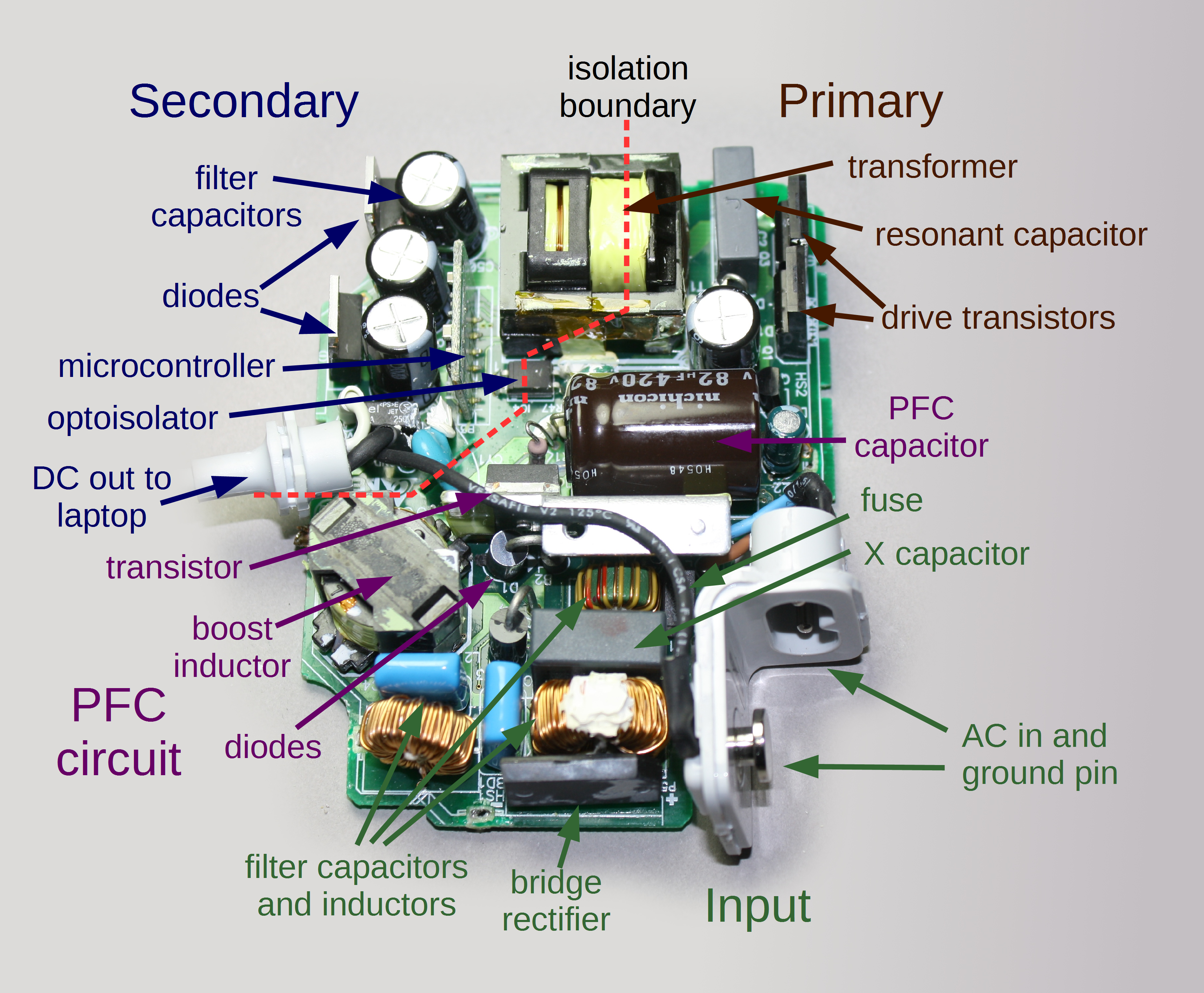
Inside the 85-watt power supply for the Apple MacBook. Despite its small size, the power supply is much more complex compared to the REC-30. It has a power factor correction circuit (PFC) to improve the efficiency of the power line. Numerous security functions (for the sake of which there is even a 16-bit microcontroller in the circuit!) Track the status of the power supply and turn it off in case of any threat or error.
Most of the weight of the MacBook's charger was dropped by replacing a huge autotransformer and anode control transformer with small high-frequency transformers. A MacBook's power supply operates at frequencies 1000 times larger than REC-30, which allows inductors and transformers to be much smaller. (I wrote a more detailed article about charging the MacBook here , and about the history of power supplies here .)
In the table below I summarized the differences between the REC-30 and the power supply of the MacBook.
| REC-30 | MacBook 85W | |
|---|---|---|
| Weight | 47.4kg | 0.27kg |
| Dimensions | 64.5cm x 20.3cm x 27.9cm (36.5 liters) | 7.9cm x 7.9cm x 2.9cm (0.18 liters) |
| AC input current | 95-250V, 25-60Hz | 100-240V, 50-60Hz |
| Output current | 108W, 120V DC at 0.9A | 85W, 18.5V DC at 4.6A |
| Single (parasitic) energy consumption | 60W | less than 0.1W |
| Content of harmful substances | Mercury, lead solder, possibly asbestos insulation of wires | No ( RoHS certified ) |
| External management | Bimetal timer and relay | 16-bit MSP430 microcontroller |
| Switching elements | Thyratron tubes 323 | N-channel power 11A MOSFETs |
| Voltage reference | Neon gas discharge lamp GE NE-42 | BandMap TSM103 / A |
| Switch control | pentode 6F6 | Resonance Controller L6599 |
| Switching frequency | 120 Hz | about 500 kHz |
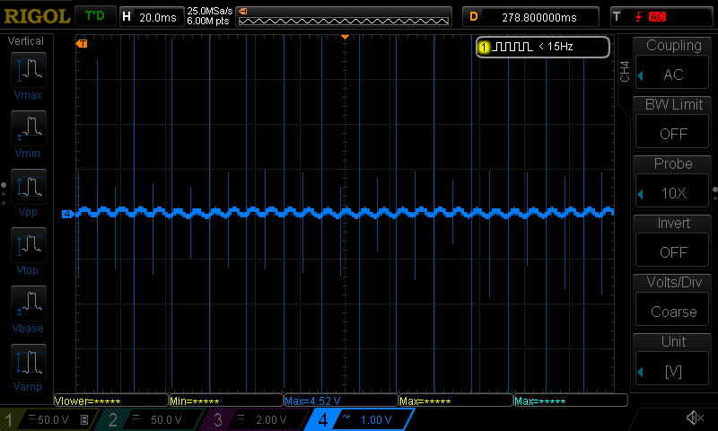
I measured the quality of the REC-30 output signal (in the image below). The power supply produces a much higher quality signal than I expected - a pulsation of only 200 mV (waves on the blue horizontal line), which is very close to the level of Apple devices. However, the oscillogram also shows narrow bursts (vertical lines) of about 8 volts, which occur when switching thyratrons. These bursts are very large compared to the power supply from Apple, but still much less than in cheap chargers .
The output signal of the power supply REC-30. You can see a slight ripple and surges when switching power.
Conclusion
The REC-30 power supply delivers over 100 watts of DC power for a teletype. Released in the 1940s, the REC-30 was an extremely early switching power supply using mercury thyratron tubes for greater efficiency. It was monstrously large for a 100W power supply: the weight was more than 45 kilograms. A comparable modern power unit is smaller and lighter by more than 100 times. Despite its age, the power supply worked flawlessly, as you can see in Mark's video. In addition, the work process itself looks very nice - the blue glow from the tiratrons and the orange from the large neon lamp.
Thanks to Carl Claunch and Marc Verdiell for their work with this power supply!
Notes
1. The first mention of the introduction of teletypes for the Navy was in the magazine BuShips Electron from September 1945. The development of a radioteletype (RTTY), in which frequency manipulation (FSK) is commonly used, allowed the use of teletypes for the needs of the Navy. At first, the fleet used radioteletayps only for communication between coastal stations between themselves, and only then began to use them on ships. The key advantage of the teletype was speed: it was four times faster than sending a message by radio by an operator manually. In addition, messages on punched tape could be automatically copied and forwarded. Also , the teletype could be integrated with cryptographic equipment, such as SIGTOT , based on a cryptosystem of disposable notebooks. You can read more about WWII teletypes.here . ↑
2. In the 1870s, Emile Bodo invented a 5-bit code named after him. Another 5-bit code was created by Donald Murray in 1901 and was standardized as ITA-2 (CCITT-2). Both coding schemes look haphazard - the characters appear scattered in random order. However, the original Bodo code was also the Gray code, and Murray's code was optimized to make fewer perforations for the most common symbols, which allowed reducing the wear of mechanisms. 5-bit codes were relevant before ASCII standardization in the 1960s, in which the alphabetic and binary order of the characters are the same. ↑
3. More detailed information on how the teletype works - here . In addition, there is an even more extensive document - Fundamentals of Telegraphy (Teletypewriter) , Army Technical Manual TM 11-655, 1954. The drawings on the REC-30 can be downloaded from here , and the documentation here . ↑
4. Note that, in contrast to a system based on voltage measurement, the components of the current loop, as the name implies, must form a topological loop in order for current to flow through them. If you exclude any device from the chain, then the loop will break if there is no loop closing mechanism. As a result, the teletype communication system contains many sockets that close when the component is disconnected in order for the current loop to continue to function. ↑
5. The main reason that the REC-30 is so large and heavy, compared to modern switching power supplies, is that the pulse frequency is only 60 Hz, while modern power supplies operate at a frequency of tens of kilohertz. Since the EMF of a transformer is proportional to the frequency of its operation, high-frequency transformers can be much smaller in size than low-frequency ones ( more ). ↑
6. REC-30 can operate with a wide range of input voltages (95, 105, 115, 125, 190, 210, 230, 250 volts AC) and currents of various frequencies (25, 40, 50 and 60 Hz). Modern pulse power supplies automatically adjust to the input voltage, but the REC-30 requires connecting the contact to the corresponding terminal of the autotransformer to change the input voltage. You might find the 25Hz frequency very strange for the input current of the power supply, but many US regions used 25 Hz power in the 1900s. In particular, Niagara Falls generated an electric current of 25 Hz due to the design features of the turbines. In 1919, more than 2/3 of the energy output in New York was at a frequency of 25 Hz, and in Buffalo it was only in 1952 that they began to use a 60 Hz current in large volumes than 25 Hz.more ). ↑
7. Isolating input AC from output DC is a key safety element in most power supplies, including chargers, computer power supplies, and the considered REC-30. This decoupling prevents strong electric shock in contact with the output contacts. For REC-30, the anode transformer plays a critical role as an insulator. Note that the autotransformer does not provide any insulation protection, since it has only one main winding and to touch its output is the same as touching the AC input current. The rest of the circuit is carefully designed so that there is no direct path between the input and the output: the control system is entirely on the secondary side, the filaments of the thyratrons are fed from the winding, isolated from the autotransformer, and relays provide isolation to the timer. In addition, the 120V output is made push-pull instead of grounding one of the contacts: this means that you need to grab 2 contacts at once to get an electric shock.↑
8. Modern pulse power supplies use pulse-width modulated (PWM) circuits to switch power at a frequency of thousands of times per second. This allows them to have a much smaller size and a smoother output than the power supplies, which switch only once in one AC cycle. But at the same time, they need a much more complex management system. ↑
9. The current solid-state equivalent of tiratrons is a silicon rectifier , which is also called SCR or thyristor (a combination of the words "tiratron" and "transistor"). SCR has four semiconductor layers (compared to a 2-layer diode and a 3-layer transistor). Just like the thyratron, the SCR is in the off state until current is applied to the control electrode. The SCR remains on and acts as a diode until the voltage drops to 0 (strictly speaking, until the flowing current becomes less than the holding current). A triac is a semiconductor element, very similar to SCR, except that it transmits current in both directions, which makes it more convenient in alternating current circuits. ↑
10. Initially, I thought that, with increasing load, the thyratrons would be open for longer periods of time in order to provide more current. However, after connecting the oscilloscope and studying the behavior of the thyratrons under different loads, I did not notice any phase shift. It turned out that this is the expected behavior: the transformer produces in general a constant voltage, regardless of the load. Thus, the timings of the thyratrons remain constant with changes in the load, and the transformer simply produces more current. In this video you can see how the luminescence of the thyratrons changes with increasing current strength. ↑
11. Under a light load, the power supply may even occasionally skip the AC cycle completely, instead of switching the thyratrons in between. Visually, this can be seen as the flickering of tiratrons, instead of a constant glow. Not sure if it's a bug or a feature. ↑
12. On the oscillogram, the yellow and blue-green lines indicate the voltage on two thyratrons. The flat part of the lines (at this moment the difference in voltages is near zero) means that at this moment the thyratron is turned on. Thyratron tubes are asymmetrical, and therefore the one to which the yellow signal is fixed usually switches on later (visually, one thyratron glows brighter than the other). The pink line is the voltage of the control grid. Note that it increases in order to increase the output voltage, and this increase causes the thyratrons to operate earlier. The vertical splash of the pink line is just noise due to the triggering of thyratrons. The blue line below is the output voltage (inverted: the line goes down as the voltage rises).
For me, the mystery is why always at least one thyratron works - constantly either the yellow or blue-green lines are at zero. I would expect to see a gap between zero voltage on one thyratron and the moment of opening the second. I suspect that large inductors induce a negative charge on the cathode, thus, even when the anode itself is negative, the potential difference between the cathode and the anode is still positive. ↑
13. A 20-second delay before powering the tubes is achieved by a timer and a relay. The timer uses a bimetal plate with a preheater. When you turn on the power supply, the cathode receives power immediately
to warm up the tubes. At the same time, the heater inside the timer heats the bimetallic plate and at some point the plate bends enough to close the contacts and power the tubes. At the same time, the relay is activated and in turn also closes the contacts. ↑
14. The cathode-related circuit is a bit tricky, since the filaments of the thyratrons are used both as heating tubes and directly as cathodes. They are fed 2.5V from the autotransformer. In addition, since the filaments in the thyratrons of the filament are also cathodes, they themselves produce an output voltage and are connected to the high side of the output signal. In order to ensure the fulfillment of both tasks, the split winding of the autotransformer imposes a voltage of 2.5V on the filament, but at the same time passes the output voltage directly. Both thyratrons use a total of 35W on the filament only, so that, as you can see, heating spends a lot of energy and generates a lot of heat, and thus, in some way, negates the benefits of a switching power supply. ↑