Creating a nanoCAD distribution with user settings

In large organizations, the process of preparing and setting up designer jobs is often difficult and routine. It would seem that to solve such a trivial task as installing CAD, you don’t need to spend a lot of resources, you just need to distribute the distribution package through domain policies or simply “share” the folder with the finished distribution kit and boldly start working in the CAD system. The question arises: “What if the organization has its own standards for processing documentation, if there are own developments in the form of ready-made blocks or teams? "Do you plan to use a common database (if SPDS, Reinforced Concrete, or Construction Site is used)?"
In this case, we are faced with yet another task - to configure user workstations, and doing this with each place separately is extremely irrational. Distributing an already configured distribution is the only right solution. Where does nanoCAD store its settings? How to create your own distribution kit? We will consider these and some other questions in more detail. The instruction is intended for machines running Windows 7 and higher.
Distribution Preparation
You must download the product distribution package from nanocad.ru . In our example, we will work with the nanoCAD SPDS 6 distribution package NCSP60x32_468.exe .
You need to install the program, because in the future we will work with its files. After installation, let's move on to the distribution .exe file.
Unpack the downloaded .exe file (for example, using the 7-zip archiver) into an arbitrary folder (in our case, we called it nanoInstall). After unpacking, we get the following set of files, presented in Fig. 1.
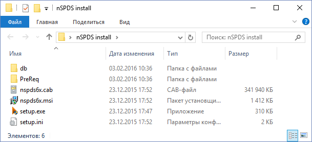
Fig. 1. Unpacked distribution kit nanoCAD СПДС 6
The nanoCAD program stores its settings in several files located in different directories. For the correct distribution deployment, it is necessary to decompose these settings into different folders. Therefore, we will create a folder in nanoInstall to store the LocalEx settings with subdirectories, as shown in Fig. 2.
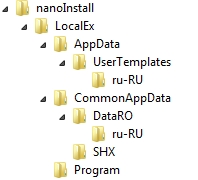
Fig. 2 Folder structure of a custom distribution
After creating the necessary folder structure in nanoinstall, you need to find and prepare configuration files that are responsible for the settings of our distribution (Settings.xml; AppOptions.xml; CAD.cfg; nCAD.ini and others).
They are located in the appropriate directories, which will be discussed below.
Note: We can change the settings on the already installed nanoCAD, but for them to take effect, you must reset the interface settings (Fig. 3) or clear the registry.
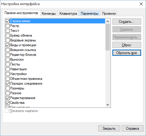
Fig. 3. NanoCAD interface settings window
More on configuration files
There are several configuration files: some are responsible for the program interface, others are for design elements, and others are for general platform settings. Below will be presented all the files separately. For a better understanding, we introduce small notation for the location of the files.
| On pc | file storage location on your computer with nanoCAD preinstalled. |
| On the installation disk | this is the path where the modified configuration files should be placed after completing the settings. |
Default.ntb
| On pc | C: \ Users \ User \ AppData \ Roaming \ Nanosoft \ nanoCAD SPDS 6.0 \ ru-RU |
| On the installation disk | nanoInstall \ LocalEx \ AppData \ UserTemplates \ ru-RU |
Data is configured through the program interface.
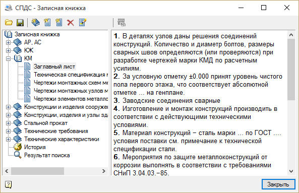
Fig. 4. Notebook nanoCAD СПДС
tinfo.xml
| On pc | C: \ Users \ User \ AppData \ Roaming \ Nanosoft \ nanoCAD SPDS 6.0 \ ru-RU |
| On the installation disk | nanoInstall \ LocalEx \ AppData \ UserTemplates \ ru-RU |
std.mcs
| On pc | C: \ ProgramData \ Nanosoft \ nanoCAD SPDS 6.0 \ DataRO \ ru-RU |
| On the installation disk | nanoInstall \ LocalEx \ CommonAppData \ DataRO \ ru-RU |
Data is configured through the program interface.
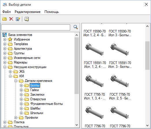
Fig. 5. Database of nanoCAD SPDS objects
Settings.xml
| On pc | C: \ ProgramData \ Nanosoft \ nanoCAD SPDS 6.0 \ DataRO \ ru-RU |
| On the installation disk | nanoInstall \ LocalEx \ CommonAppData \ DataRO \ ru-RU |
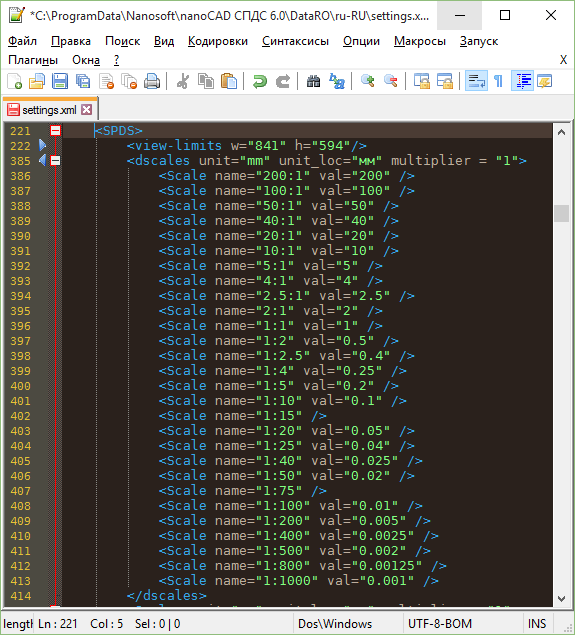
Adding a design scale to the list of standard scales
To add nanoCAD value to a new design scale, you need to find the appropriate code in the tags ... (Fig. 6.1) in the Settings.xml file and edit the existing scale list. The xml file contains comments about parameter assignment. So, for example, you can specify the scale that will be used by default. Adding your scale to the list:We assign the default value to a scale of 1: 400:
 |  |
| Fig. 6.1. Scale List Code | Fig. 6.2. Customized Scale List |
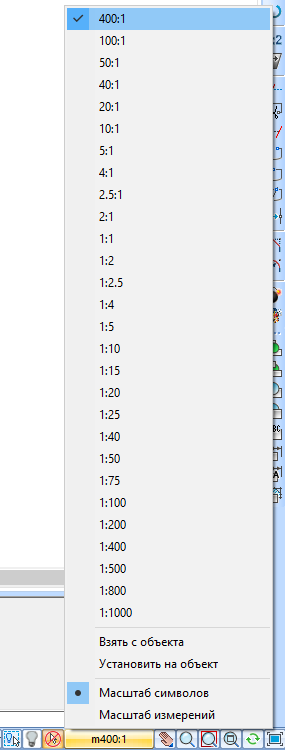
Adding a measurement scale to the list of standard scales
To add a nanoCAD value to a non-standard measurement scale, you need to find the corresponding code in the Settings.xml file (Fig. 7.1) and add similar lines with your parameters to the existing scale list. The xml file contains comments about parameter assignment.Adding your scale to the list:
In fig. 7.1 the code of the list of measurement scales and the corresponding list of scales in the nanoCAD window are compared.
 |  |
| Fig. 7.1. Measurement Scale List Code | Fig. 7.2. Customized list of measurement scales |
AppOptions.xml
| On pc | C: \ Users \ User \ AppData \ Roaming \ Nanosoft \ nanoCAD SPDS 6.0 \ ru-RU |
| On the installation disk | nanoInstall \ LocalEx \ AppData \ UserTemplates \ ru-RU |
As an example, we will change the settings of the position leader in the SPDS profile, as shown in Fig. 8. We changed the color of the leader lines and the line thickness. Overridden values are highlighted in blue - these are the settings that differ from the standard AppOptions.xml file.

Fig. 8. The window for setting the position leader
After completing the settings, they must be saved in an xml file. Click File → Save Settings As. Specify the folder nanoInstall \ LocalEx \ AppData \ UserTemplates \ ru-RU \ and click the Save button (Fig. 9).
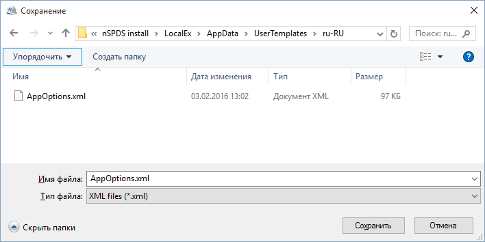
Fig. 9. Saving the settings file AppOptions.xml
Myblocks.hsf
| On pc | C: \ Program Files (x86) \ Nanosoft \ nanoCAD SPDS 6.0 |
| On the installation disk | nanoInstall \ LocalEx \ Program |
ncadbase.cfg and userdata.cfg
| On pc | C: \ Program Files (x86) \ Nanosoft \ nanoCAD SPDS 6.0 |
| On the installation disk | nanoInstall \ LocalEx \ Program |
Note: to see the changed settings of cfg files in the program, you need to clear the nanoCAD SPDS registry in the HKEY_LOCAL_MACHINE \ SOFTWARE \ Nanosoft \ nanoCAD SPDS branch after saving the settings.
Application preload
The created nsf file with commands (you can read about this in the last article) must be loaded in the program at startup. Previously, for this, we used the option Download applications (Tools → Applications → Download applications → Startup). To preset this option, we will register a special command that will load the nsf file.
[\configman\commands\sload_myblocks_nsf]
weight=i30   |cmdtype=i0 | intername=sload_myblocks_nsf
RealCommandName=snsf
Keyword=smyblocks.nsf^MCloseDocument^MNewDocument^M
Change context menu
nanoCAD 7 does not support CUI files, however we have access to all cfg files that are responsible for the interface settings.Let's try changing the standard context menu. In fig. 10a presents the standard nanoCAD context menu. Go to the folder with the product C: \ Program Files \ Nanosoft \ nanoCAD SPDS 6.0 in the file ncadbase.cfg and find the lines describing the standard right-click menu. They are represented by a list with the prefix \ ViewPopupMenu \.
[\ViewPopupMenu]                                                 |Intername=sViewPopupMenu
[\ViewPopupMenu\LastCommand]                     |intername=sLastCommand1
[\ViewPopupMenu\LastCommandPopup]         |name=s&Last commands
[\ViewPopupMenu\LastCommandPopup\LC0] |intername=sLastCommand1
….
[\ViewPopupMenu\Inspector]                     |name=sP&roperties             |intername=sProperties
[\ViewPopupMenu\DrawingExplorer]         |name=sDrawing &Explorer             |intername=sDrawingExplorer

Fig. 10a. The standard right-click menu nanoCAD SPDS
The standard menu seemed to me too large, and I made some changes to it: removed some commands, grouped others into drop-down items and added several new commands. As a result, I got the following code:
Reveal code
[\ViewPopupMenu]                                               |Intername=sViewPopupMenu
[\ViewPopupMenu\LastCommand]          |intername=sLastCommand1
[\ViewPopupMenu\LastCommandPopup]     |name=s&Last commands
[\ViewPopupMenu\LastCommandPopup\LC0] |intername=sLastCommand1
[\ViewPopupMenu\LastCommandPopup\LC1] |intername=sLastCommand2
[\ViewPopupMenu\LastCommandPopup\LC2] |intername=sLastCommand3
[\ViewPopupMenu\LastCommandPopup\LC3] |intername=sLastCommand4
[\ViewPopupMenu\LastCommandPopup\LC4] |intername=sLastCommand5
[\ViewPopupMenu\LastCommandPopup\LC5] |intername=sLastCommand6
[\ViewPopupMenu\LastCommandPopup\LC6] |intername=sLastCommand7
[\ViewPopupMenu\LastCommandPopup\LC7] |intername=sLastCommand8
[\ViewPopupMenu\LastCommandPopup\LC8] |intername=sLastCommand9
[\ViewPopupMenu\sep2]
[\ViewPopupMenu\Undo]                           |name=s&Undo               |intername=sEditUndo
[\ViewPopupMenu\Redo]                           |name=s&Redo                |intername=sEditRedo
[\ViewPopupMenu\sep3]
[\ViewPopupMenu\Move]                           |name=sMove object
[\ViewPopupMenu\Move\erase]                     |name=sErase       |intername=sDelete
[\ViewPopupMenu\Move\MoveCopy]                  |Name=sCop&y                        |InterName=sMoveCopy
[\ViewPopupMenu\Move\Mirror]                    |Name=sMirror                      |InterName=sMirror
[\ViewPopupMenu\Move\Offset]                    |name=sOffset               |intername=svcOffsetCmd
[\ViewPopupMenu\Move\Array]                     |Name=sArray                       |InterName=sArray
[\ViewPopupMenu\Move\sep4]
[\ViewPopupMenu\Move\MoveObject]                      |Name=sMov&e       |InterName=sMove
[\ViewPopupMenu\Move\RotateObject]                    |Name=s&Rotate     |InterName=sRotate
[\ViewPopupMenu\Move\sep10]
[\ViewPopupMenu\Move\scale]                     |Name=s&Scale                       |InterName=sScale
[\ViewPopupMenu\Move\stretch]                   |name=sStretch       |intername=sstretch
[\ViewPopupMenu\Move\sep5]
[\ViewPopupMenu\Move\Trim]                      |name=s&Trim Vectors               |intername=svcTrimByEdgeCmd
[\ViewPopupMenu\Move\smarttrim]                    |name=sSmart &Trim      |intername=ssmarttrim
[\ViewPopupMenu\Move\Extend]                    |name=s&Extend Vectors      |intername=svcExpandByEdgeCmd
[\ViewPopupMenu\Move\Break]                     |name=s&Break Vectors               |intername=svcBreakCmd
[\ViewPopupMenu\Move\Join]                      |name=s&Join objects               |intername=sJoin
[\ViewPopupMenu\Clipboard] |name=sБуфер обмена
[\ViewPopupMenu\Clipboard\Cut]   |Name=s&Cut   |InterName=sCut
[\ViewPopupMenu\Clipboard\Copy]   |Name=s&Copy   |InterName=sCopy
[\ViewPopupMenu\Clipboard\CopyWithBasePoint]  |Name=s&Copy With Base Point                |InterName=sCopyWithBasePoint
[\ViewPopupMenu\Clipboard\Paste]                           |Name=s&Paste                     |InterName=sPaste
[\ViewPopupMenu\Clipboard\PasteBlock]                |Name=s&Paste as Block      |InterName=sPasteBlock
[\ViewPopupMenu\Clipboard\PasteOriginal]  |Name=sPaste to Original Coor&dinates      |InterName=sPasteOrigin
[\ViewPopupMenu\Isolate]                           |name=sIsolate
[\ViewPopupMenu\Isolate\IsolateObjects]            |name=sIsolate &Objects          |InterName=sIsolateObjects
[\ViewPopupMenu\Isolate\HideObjects]               |name=sHide Objects             |InterName=sHideObjects
[\ViewPopupMenu\Isolate\UnisolateObjects]          |name=sUnisolate Objects        |InterName=sUnisolateObjects
[\ViewPopupMenu\DisplayOrder]                           |name=sDispla&y Order
[\ViewPopupMenu\DisplayOrder\BringToFront]              |name=s&Bring to Front    |InterName=sdraworder1
[\ViewPopupMenu\DisplayOrder\SendToBack]                |name=s&Send to Back      |InterName=sdraworder2
[\ViewPopupMenu\DisplayOrder\BringForward]              |name=sBring &Forward     |InterName=sdraworder3
[\ViewPopupMenu\DisplayOrder\SendBackward]              |name=sSend Back&ward     |InterName=sdraworder4
[\ViewPopupMenu\Select]							|name=sSelect
[\ViewPopupMenu\Select\selectsimilar]				|name=sSelect similar objects        |intername=sselectsimilar
[\ViewPopupMenu\Select\SelectAll]                     |name=sSelect Al&l          |intername=sSelectAll
[\ViewPopupMenu\Select\QuickSelect]                   |name=s&Quick Select        |intername=sqs
[\ViewPopupMenu\Select\UnSelectAll]                     |name=sUnSelect All          |intername=sUnSelectAll
[\ViewPopupMenu\sep1]
[\ViewPopupMenu\AddSelected]   |Name=sAdd Selected   |InterName=sAddSelected
[\ViewPopupMenu\sep5]
[\ViewPopupMenu\Find] |name=sSearch and Replace... |intername=sfind
[\ViewPopupMenu\sep4]
[\ViewPopupMenu\Inspector]                 |name=sP&roperties             |intername=sProperties
[\ViewPopupMenu\preferences]			|name=sPreferences             |intername=sPreferencesCmd
After editing is complete, save the ANSI encoded file. In fig. 10b presents the result of the changes made.
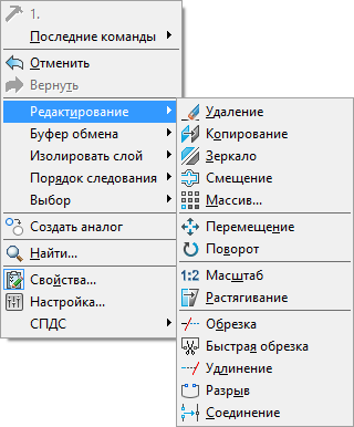
Fig. 10b. New right-click menu
If you configure the context menu on an already installed nanoCAD, then after saving the changes to the ncadbase.cfg file, you need to clear the nanoCAD SPDS registry in the HKEY_LOCAL_MACHINE \ SOFTWARE \ Nanosoft \ nanoCAD SPDS branch.
nprof.ini (nApp.ini)
| On pc | C: \ Program Files (x86) \ Nanosoft \ nanoCAD SPDS 6.0 |
| On the installation disk | nanoInstall \ LocalEx \ Program |
In our example, we will place the standard nanoCAD folders (templates, fonts, print styles, forms) in a shared folder on the server and add our own dwt template, which we will use by default.
- Create the necessary directories on the server:
\\ Server \ Templates
\\ Server \ shx
\\ Server \ PlotConfigs
\\ Server \ PlotStyles - We create the test.dwt template and place it in the folder on the server: \\ Server \ Templates \ test.dwt .
- Using notepad, create the nApp.ini file and copy the necessary settings into it from nprof.ini or from the finished example below.
[\DefProf\StdDirs]
TemplatesDir=s\\ServerTemplates
Shx=s\\Server\shx
PlotConfigsDir=s\\Server\PlotConfigs
PlotStylesDir=s\\Server\PlotStyles
Pat=s\\Server\shx
[\DefProf\TemplateDoc]
UseTemplateFile=i1
TemplateName=sTest.dwt
[\DefProf\TemplateImport]
UseTemplateFile=i1
TemplateName=sTest.dwt
Note:
[\ DefProf \ StdDirs] - this section contains the parameters of the standard folders.
[\ DefProf \ TemplateDoc] and [\ DefProf \ TemplateImport] are the parameters for using templates for new and imported documents, respectively.
In fig. Figure 11 shows the result of changes to the nrof.ini settings file.
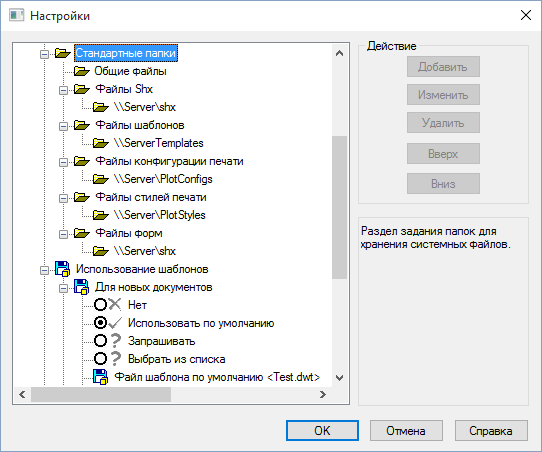
Fig. 11. Standard folders and using templates.
Earlier we registered a special command for loading blocks, now in nApp.ini we will indicate the loading of this command at the start of nanoCAD.
[\DefProf\Startup\load_myblocks_nsf]After saving the nApp.ini file , copy it to the appropriate distribution directory. The nprof.ini file does not need to be copied.
Setup.ini
Let's move on to the setup.ini file , the last one we need to prepare. This distribution file for the distribution itself is located in the folder with the unpacked installer (nanoinstall). In it, you can register the serial number of the product or specify the address of the license server, as well as the folder for the SPDS database and the path to the STP settings. To configure the installation, uncomment the keys and set their own values for them. Only the keys in the [InstallProperties] section need to be edited. When uncommenting the parameters, do not forget to uncomment the [InstallProperties] section. Below is a list of available options.
Сервер лицензий
FLEXLM_VENDOR_NAME=Nanosoft
FLEXLM_LICENSE_FILE=@server
Серийный номер
SERIALNUMBER=ZZZ10-TRIAL-00000
Директория установки
INSTALLLOCATION=c:\Best program
Папка локальной БД
DATABASE_PATH=c:\std.mcs
Путь до БД в сети
DATABASE_PATH=SQL:SERVER:base
Папка хранения локальных настроек
SETTINGS=\\server\Settings.xml
Папка СТП на сервере
CORP_OPTIONS=\\server\CorpOptions.xml
The prefix name of the current profile is implemented by adding a prefix to the layer names. Manually, you can change it in the design settings: Main Settings → General Settings → Current Profile.
APP_OPTIONS_PROFILE = name
If any of these keys is commented out, then it will be set to the default value stored in the application.
Transfer settings files
After finishing editing all the above files, they must be placed in the appropriate installer directories (nanoinstall) . If you use additional files (scripts, lisp, etc.), they can be placed in the Program folder ( nanoInstall \ LocalEx \ Program ) and during installation they will be placed in the Program Files product folder.
Silent Installation
Such parameters are necessary if you intend to install a customized distribution locally.
Using notepad, create a new text file with the extension .bat in the nanoInstall folder (Fig. 8) and specify one of the two installation parameters:
- to install in passive mode (displaying the installation progress dialog, but without user intervention), run setup.exe / i / passive
- to install in silent mode (for the user, even the installation dialog will not be displayed) you need to run Setup.exe / i / quiet

Fig. 12. Creating a bat-file to run the installer
Conclusion
We showed you how you can adapt nanoCAD to your settings, save them in your files and include in your installation package, which is very convenient for deploying nanoCAD on a large number of workstations within the enterprise network. With the help of this knowledge, you will not only simplify your life when installing the software, but also be able to control the unified CAD settings at all user workstations: all users will now work with unified templates, fonts, design settings, etc. You can even put your scripts and commands on each user's workstation.
It remains to note that this article will be useful for installing not only nanoCAD SPDS, but also for other vertical solutions and for the nanoCAD platform itself. Have a good design!
Sergey Spirin, mahbak
Nanosoft CJSC