What you need to know when configuring ePMP 1000 transmitter power from Cambium Networks
When configuring links on Cambium Networks' ePMP 1000 equipment, questions often arise regarding the configuration of the transmitter power, both on the side of the base station and on the subscriber stations.
Frequently asked questions: why the real power of the transmitter differs from that configured on the UI, why the real power periodically downloads on devices, although the settings have not changed, and others.
Today we’ll try to consider all the nuances of the transmitter power configuration.
To begin with, all devices of the ePMP 1000 line with the latest available firmware version (2.6) have 3 main robot (protocol) modes:
- TDD - a mode of operation with a fully implemented TDD mechanism and GPS synchronization, for working in PMP (point-to- multipoint). For PTP (point-to-point) links, TDD PTP can be used, which is the same TDD mode with restriction on connecting one subscriber station;
- ePTP Master / Slave - a mode that does not support GPS synchronization, for operation in PTP (point-to-point) mode with a minimum value of transmission delay;
- Standard W-Fi - a mode based entirely on the standard 802.11n.
Also, each ePMP device can be used as a base station (AP - Access Point) or a subscriber station (SM - subscriber module).
The difference between the display of the transmitter power on the AP and SM.
I want to emphasize right away that to understand this issue you need to know about the differences in the processing of subscriber traffic and control traffic on ePMP equipment.
Subscriber traffic will always be transmitted on the highest possible MCS. The control traffic is always transmitted to MCS1 or 0 depending on the configuration (option available on the UI). Thus, the transmitter power for transmitting management and information packets will differ (we will return to this a bit later).
Thus, the transmission power of management traffic is always displayed on the AP, and the transmission power of data traffic on the SM.
This is no accident, the AP can transmit traffic to each SM in PMP mode on its MCS, and accordingly, with its own power, and only the transmission power of data packets is the same for all SMs.
In general, three basic limitations affect transmitter power:
- Regulatory
- ATPC (Adaptive Transmission Power Control) - ATPC only works in TDD mode!
- Dynamic TX Power
Regulator - Transmitter power limitation in accordance with the requirements of the competent authorities, depending on the country code used. Depends on the Country Code used, frequency band, robot mode (PMP / PTP). It works on both AP and SM.
ATPC (Adaptive Transmission Power Control) - adaptive automatic power control mechanism. The mechanism is designed to reduce secondary Uplink interference when working on multi-sector towers with frequency reuse. Secondary interference is called interference at a particular base station from an SM from a neighboring sector. Reducing the effect of secondary interference is achieved by reducing the "excess" power on the SM.
ATPC settings are configured on the AP side in the Power Control section of the UI. The only parameter is the Subscriber Module Target Receive Level, i.e. desired UL signal strength from SM. Thus, if the AP receives a signal with a level higher than that specified in the Subscriber Module Target Receive Level, then the transmitter power on the SM will be automatically reduced. Conversely, if the capacity is insufficient, then it will be increased, if it will be possible in accordance with the Regulation.

On the SM side, there is a Tx Power configuration option - Auto or Manual. In auto mode, the configuration is automatic, which is understandable.
However, the Manual option should not be misleading, in this Tx Power mode the ATPC is also regulated, the value set on the UI will only be the upper level above which the ATPC will not be able to raise the transmit power on the SM.

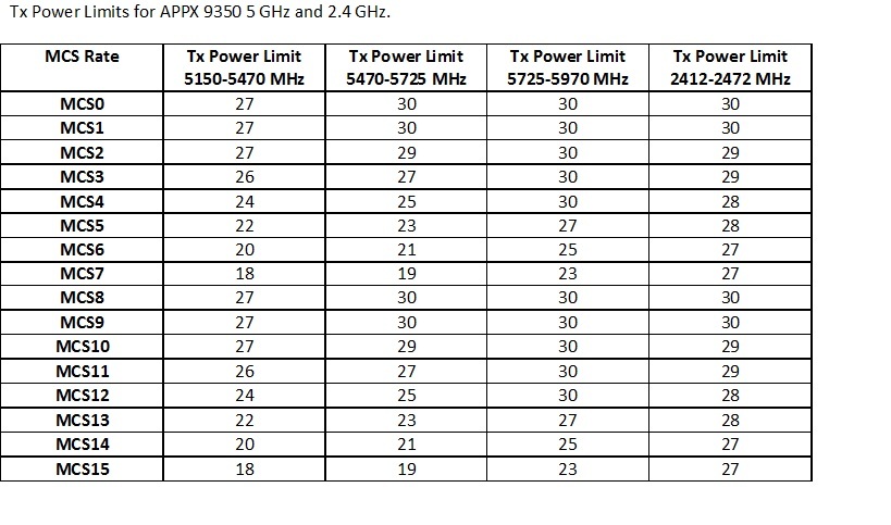
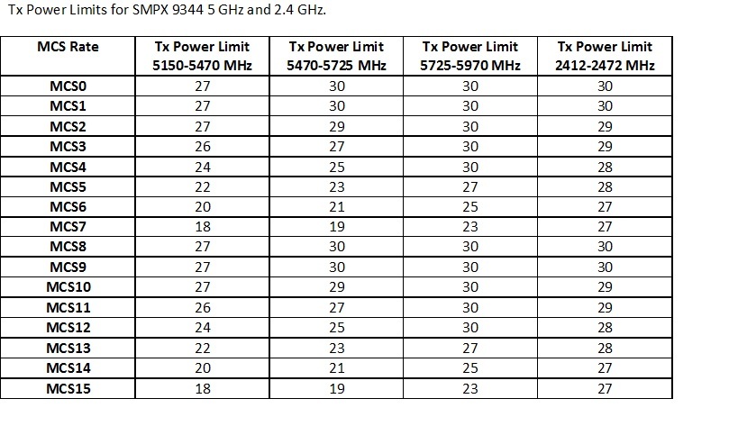
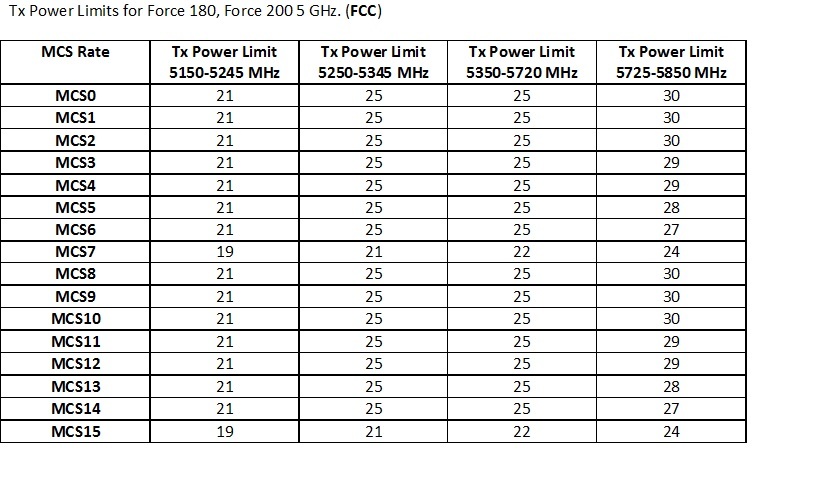
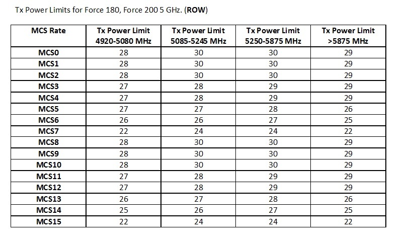
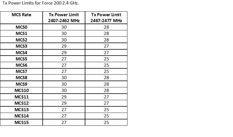
Dynamic TX Power - a limitation caused by the quality of the transceiver system. Transmitter power limitation is associated with an increase in the error vector magnitude (EVM - Error Vector Magnitude) with higher MCS with more complex types of modulation. The limitation has a frequency dependence and also depends on the type of device. There are separate Dynamic Tx Power restriction tables for each ePMP device.
Frequently asked questions: why the real power of the transmitter differs from that configured on the UI, why the real power periodically downloads on devices, although the settings have not changed, and others.
Today we’ll try to consider all the nuances of the transmitter power configuration.
To begin with, all devices of the ePMP 1000 line with the latest available firmware version (2.6) have 3 main robot (protocol) modes:
- TDD - a mode of operation with a fully implemented TDD mechanism and GPS synchronization, for working in PMP (point-to- multipoint). For PTP (point-to-point) links, TDD PTP can be used, which is the same TDD mode with restriction on connecting one subscriber station;
- ePTP Master / Slave - a mode that does not support GPS synchronization, for operation in PTP (point-to-point) mode with a minimum value of transmission delay;
- Standard W-Fi - a mode based entirely on the standard 802.11n.
Also, each ePMP device can be used as a base station (AP - Access Point) or a subscriber station (SM - subscriber module).
The difference between the display of the transmitter power on the AP and SM.
I want to emphasize right away that to understand this issue you need to know about the differences in the processing of subscriber traffic and control traffic on ePMP equipment.
Subscriber traffic will always be transmitted on the highest possible MCS. The control traffic is always transmitted to MCS1 or 0 depending on the configuration (option available on the UI). Thus, the transmitter power for transmitting management and information packets will differ (we will return to this a bit later).
Thus, the transmission power of management traffic is always displayed on the AP, and the transmission power of data traffic on the SM.
This is no accident, the AP can transmit traffic to each SM in PMP mode on its MCS, and accordingly, with its own power, and only the transmission power of data packets is the same for all SMs.
In general, three basic limitations affect transmitter power:
- Regulatory
- ATPC (Adaptive Transmission Power Control) - ATPC only works in TDD mode!
- Dynamic TX Power
Regulator - Transmitter power limitation in accordance with the requirements of the competent authorities, depending on the country code used. Depends on the Country Code used, frequency band, robot mode (PMP / PTP). It works on both AP and SM.
ATPC (Adaptive Transmission Power Control) - adaptive automatic power control mechanism. The mechanism is designed to reduce secondary Uplink interference when working on multi-sector towers with frequency reuse. Secondary interference is called interference at a particular base station from an SM from a neighboring sector. Reducing the effect of secondary interference is achieved by reducing the "excess" power on the SM.
ATPC settings are configured on the AP side in the Power Control section of the UI. The only parameter is the Subscriber Module Target Receive Level, i.e. desired UL signal strength from SM. Thus, if the AP receives a signal with a level higher than that specified in the Subscriber Module Target Receive Level, then the transmitter power on the SM will be automatically reduced. Conversely, if the capacity is insufficient, then it will be increased, if it will be possible in accordance with the Regulation.
On the SM side, there is a Tx Power configuration option - Auto or Manual. In auto mode, the configuration is automatic, which is understandable.
However, the Manual option should not be misleading, in this Tx Power mode the ATPC is also regulated, the value set on the UI will only be the upper level above which the ATPC will not be able to raise the transmit power on the SM.
Dynamic TX Power - a limitation caused by the quality of the transceiver system. Transmitter power limitation is associated with an increase in the error vector magnitude (EVM - Error Vector Magnitude) with higher MCS with more complex types of modulation. The limitation has a frequency dependence and also depends on the type of device. There are separate Dynamic Tx Power restriction tables for each ePMP device.