Implementation of MODBUS RTU server using Fastwel interface module and CoDeSys software
This article discusses the integration of Fastwel's CPM713 programmable logic controller based on the MODBUS TCP protocol with a Weintek operator panel that supports the serial version of the MODBUS RTU / ASCII protocol using the NIM742 interface module and the ready-made CoDeSys adapted library for Fastwel.
Ethernet-based industrial protocols are gaining in popularity. The use of this technology in industrial systems has advantages, for example, the ability to flexibly upgrade and scale the system, the simplicity of building an architecture, and the low cost of creating networks [1]. However, the introduction of new technologies in the field of industrial control systems is rather slow, so many devices still use traditional industrial networks based on serial buses.
When creating automated systems, it is often necessary to establish data exchange between devices that support various data exchange protocols or various modifications of the same protocol.
So, the Fastwel CPM713 controller uses MODBUS TCP protocol based on Ethernet networks for data transmission [2]. When working with this controller, the task arose to transmit and receive data from the Weintek MT6100i operator panel that supports the MODBUS RTU / ASCII serial protocol (Fig. 1).

Figure 1. Integration of the Fastwel I / O controller with the Weintek operator panel
Using seamless integration is always higher priority than using third-party gateways. Therefore, to solve this problem, the Fastwel NIM742 interface module was taken, which allows connecting devices with the RS-232C interface and working with them through the CPM713 controller user program.
The NIM742 module, together with the CPM713 controller user program, implements the operation of the Modbus RTU slave. NIM742 is connected to a common line of modules and communicates with the CPM713 controller via FBUS (Fig. 2). To ensure the operation of NIM742 with the MODBUS RTU protocol, the CoDeSys FastwelModbusServer.lib library is used, which is included in the Fastwel adaptation package.
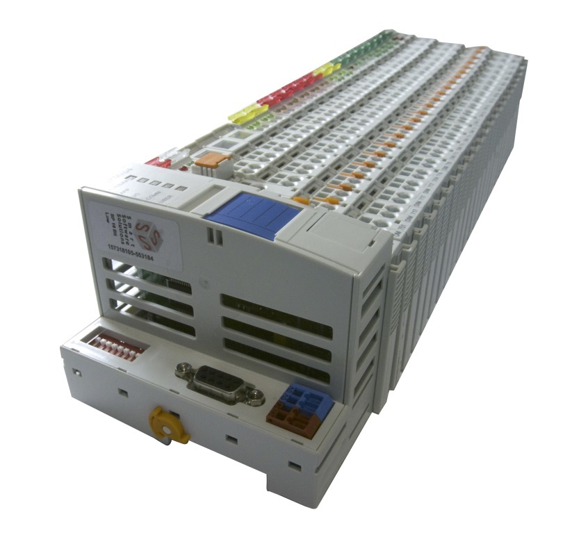
Figure 2. CPM71x controller with connected modules
The following components and accessories were used to configure and program the CPM713 controller and the NIM742 interface module:
• ACS00019 configuration cable supplied with the controller,
• 3S Smart Software Solutions , a free CoDeSys software package with Fastwel CoDeSys Adaptation adaptation package for working with Fastwel.
To work with the Weintek MT6100i operator panel, you needed:
• connecting cables for configuration, which are also included in the package,
• free software for configuring EasyBuilder 8000.
The interface module is connected to the operator panel using a connecting cable. This cable can be made independently using the pin assignment information provided in the Weintek panel user manual (Fig. 3). For communication with the NIM742 module, the operator panel COM3 [RS-232] port was used, using three contact connection for data transfer: TxD (transmit), RxD (receive) and GND (ground).

Figure 3. Pin assignment for the Weintek 6100i panel female SUB-D COM3 [RS-232]
Figure 4 shows the connection diagram of the contacts of the NIM742 module to the COM3 port of the operator panel [3, 4]. When connecting, it must be borne in mind that the TxD data transfer pin of the interface module must be connected to the operator panel RxD data receive pin, and the RxD contact, respectively, to the TxD panel.
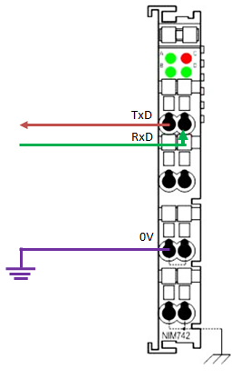
Figure 4. Connecting the NIM742 module to the operator panel COM3 port.
Thus, for communication between the operator panel and the NIM742 module, it is necessary to connect the TxD and RxD contacts with the 8th and 7th contacts of the SUB-D connector, and connect the module ground to the 5th contact (Fig. 5).
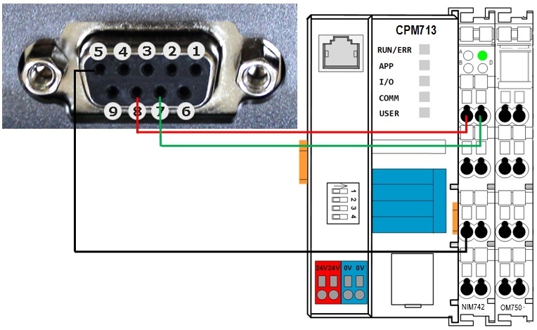
Figure 5. Connection diagram of NIM742 and Weintek MT6100i operator panel.
The screen form of the operator panel is created and configured using the free EasyBuilder8000 software. When creating a new project, you must specify the model of the Weintek panel used (Fig. 6).

Figure 6. Creating a new project in EasyBuilder8000
Next, when creating a project, you need to edit the system settings and specify a list of devices with which the operator panel communicates (Fig. 7). In our case, it will be a Modbus RTU slave [5].
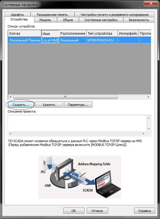
Figure 7. Project system settings
For the client we use, the following parameters are configured: PLC location, communication type, COM port, speed and operation mode (Fig. 8). These data will also be indicated in the PLC work program.

Figure 8. Settings for the new device
After entering all the communication parameters, it is necessary to add the control and display elements to the screen form: bit indicators, switches, digital indicators, etc. Figure 9 shows the appearance of the finished test project.
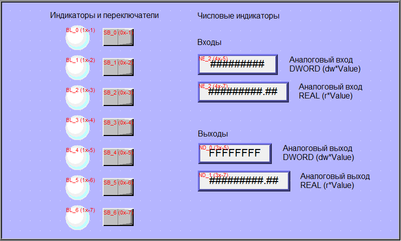
Figure 9. Test design of the panel screen.
These display and control elements are associated with MODBUS variables. The addressing of Modbus RTU variables is indicated in the manual for connecting the Weintek panel to the PLC (Fig. 10).
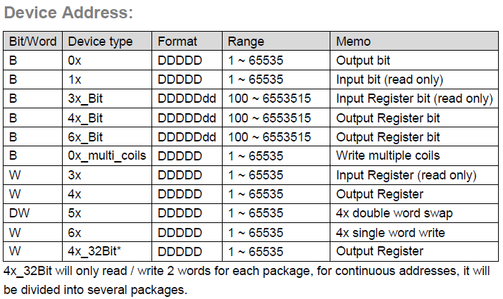
Figure 10. Table of Modbus variable addresses
The MODBUS protocol supports four types of variables:
• Discrete Input (1 bit);
• discrete output (Coil, 1 bit);
• analog input (Input Register, 16 bit);
• analog output (Holding Register, 16 bit).
To access a specific variable, you must also specify an address on the MODBUS network.
Depending on the type of variable, functions with codes 0x, 1x, 3x, 4x are used to access the data. The 0x code corresponds to the Coil type, which is the output variable for writing the value to a bit variable. The 1x address reads the status of the Discrete Input bit variable. The 3x address corresponds to the Input Register and is used to read the status of an analog variable. The 4x address writes the analog variable Holding Register.
Thus, the address of the first switch will be 0x1 (Fig. 11), the second 0x2, and so on. The addresses of all elements of the mimic screen are presented in table 1.

Fig. 11. Assignment of addresses to the elements of the working mnemonic diagram
Table 1. Addresses of the elements of the screen of the working diagram:

The test project for CPM713 is based on a ready-made example for FastwelModbusServer.lib, which is part of the CoDeSys adaptation for Fastwel. This library implements high speed, universal and easy to implement, therefore, when organizing data exchange using the Modbus RTU protocol, it is recommended to use it. FastwelModbusServer.lib implements the functionality of a MODBUS RTU / ASCII slave via the controller ports available to the user program. Including, for organizing access to the MODBUS RTU network through the port of the NIM742 module.
To organize the exchange of data between the user application and I / O modules, it is necessary to add the configuration of the I / O system according to the physical connection to the controller. In the test project, we used only the NIM742 module, and the controller configuration is shown in Figure 12.
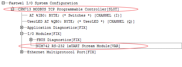
Fig. 12. List of used modules
The FastwelModbusServer library has the only FwModbusServerInit () function, which is designed to initialize and configure the server. When calling this function, the user sets the communication parameters of the network node and describes the data areas that will be displayed on the address space of the MODBUS server. Server initialization occurs only from the OnInit system event handler, which initializes the Modbus server once, after turning on the power and before the main user program is launched.
The data exchange parameters through the COM port are specified in the function itself in the area of setting local variables (Fig. 13). Here Port is the port number, BaudRate is the data exchange speed, StopBit is the length of the stop bit, Parity is the control bit mode, ByteSize is the number of bits in the frame, NodeAddress is the address of the device in the Modbus network.
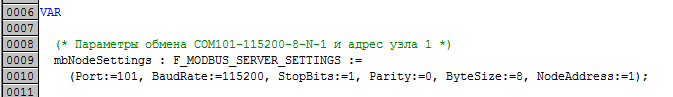
Fig. 13. Setting COM-port parameters
Data exchanged between the main program and the operator panel is set in the user data types PLC_PRG_IN (what is received via the network) and PLC_PRG_OUT (what is sent to the network). These variables are an array of four variables of the WORD type, the double word DWORD and the real number REAL (Fig. 14).

Fig. 14. Variables for Modbus communication
After the screen form and the program have been downloaded to the appropriate devices, the operator panel in the wizard mode polls the CPM713 controller. The operating screen of the operator panel in runtime is shown in Figure 15.
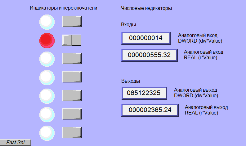
Fig. 15. Operating screen of the operator panel in runtime.
Further, if necessary, using CoDeSys tools, you can collect data received by the CPM713 controller via MODBUS TCP network and redirect them to the operator panel using MODBUS RTU protocol. Thus, using CoDeSys and the NIM742 interface module, seamless integration of the MODBUS RTU and MODBUS TCP protocols can be created.
References
1. Orlov, C. Ethernet and industrial networks / Sergey Orlov // Journal of Network Solutions / LAN. - 2013. - No. 9. - S. 24-31
2. FASTWEL I / O distributed I / O system. Manual. ftp.prosoft.ru/pub/Hardware/Fastwel/Fastwel_IO/Version2/Doc/FIO_UM.pdf .
3. Fastwel I / O I / O. I / O modules. Programmer's Guide. ftp.prosoft.ru/pub/Hardware/Fastwel/Fastwel_IO/Version2/Doc/FIO_Modules_CoDeSys_Adaptation_UM.pdf .
4. Weintek MT-600/8000 series MT-607i, MT-8070iH / MT-6070iH. Installation Instruction
5. EasyBuilder8000 User Guide.
Ethernet-based industrial protocols are gaining in popularity. The use of this technology in industrial systems has advantages, for example, the ability to flexibly upgrade and scale the system, the simplicity of building an architecture, and the low cost of creating networks [1]. However, the introduction of new technologies in the field of industrial control systems is rather slow, so many devices still use traditional industrial networks based on serial buses.
When creating automated systems, it is often necessary to establish data exchange between devices that support various data exchange protocols or various modifications of the same protocol.
So, the Fastwel CPM713 controller uses MODBUS TCP protocol based on Ethernet networks for data transmission [2]. When working with this controller, the task arose to transmit and receive data from the Weintek MT6100i operator panel that supports the MODBUS RTU / ASCII serial protocol (Fig. 1).
Figure 1. Integration of the Fastwel I / O controller with the Weintek operator panel
Using seamless integration is always higher priority than using third-party gateways. Therefore, to solve this problem, the Fastwel NIM742 interface module was taken, which allows connecting devices with the RS-232C interface and working with them through the CPM713 controller user program.
The NIM742 module, together with the CPM713 controller user program, implements the operation of the Modbus RTU slave. NIM742 is connected to a common line of modules and communicates with the CPM713 controller via FBUS (Fig. 2). To ensure the operation of NIM742 with the MODBUS RTU protocol, the CoDeSys FastwelModbusServer.lib library is used, which is included in the Fastwel adaptation package.
Figure 2. CPM71x controller with connected modules
Device connection
The following components and accessories were used to configure and program the CPM713 controller and the NIM742 interface module:
• ACS00019 configuration cable supplied with the controller,
• 3S Smart Software Solutions , a free CoDeSys software package with Fastwel CoDeSys Adaptation adaptation package for working with Fastwel.
To work with the Weintek MT6100i operator panel, you needed:
• connecting cables for configuration, which are also included in the package,
• free software for configuring EasyBuilder 8000.
The interface module is connected to the operator panel using a connecting cable. This cable can be made independently using the pin assignment information provided in the Weintek panel user manual (Fig. 3). For communication with the NIM742 module, the operator panel COM3 [RS-232] port was used, using three contact connection for data transfer: TxD (transmit), RxD (receive) and GND (ground).
Figure 3. Pin assignment for the Weintek 6100i panel female SUB-D COM3 [RS-232]
Figure 4 shows the connection diagram of the contacts of the NIM742 module to the COM3 port of the operator panel [3, 4]. When connecting, it must be borne in mind that the TxD data transfer pin of the interface module must be connected to the operator panel RxD data receive pin, and the RxD contact, respectively, to the TxD panel.
Figure 4. Connecting the NIM742 module to the operator panel COM3 port.
Thus, for communication between the operator panel and the NIM742 module, it is necessary to connect the TxD and RxD contacts with the 8th and 7th contacts of the SUB-D connector, and connect the module ground to the 5th contact (Fig. 5).
Figure 5. Connection diagram of NIM742 and Weintek MT6100i operator panel.
Setting the operator panel
The screen form of the operator panel is created and configured using the free EasyBuilder8000 software. When creating a new project, you must specify the model of the Weintek panel used (Fig. 6).
Figure 6. Creating a new project in EasyBuilder8000
Next, when creating a project, you need to edit the system settings and specify a list of devices with which the operator panel communicates (Fig. 7). In our case, it will be a Modbus RTU slave [5].
Figure 7. Project system settings
For the client we use, the following parameters are configured: PLC location, communication type, COM port, speed and operation mode (Fig. 8). These data will also be indicated in the PLC work program.
Figure 8. Settings for the new device
After entering all the communication parameters, it is necessary to add the control and display elements to the screen form: bit indicators, switches, digital indicators, etc. Figure 9 shows the appearance of the finished test project.
Figure 9. Test design of the panel screen.
These display and control elements are associated with MODBUS variables. The addressing of Modbus RTU variables is indicated in the manual for connecting the Weintek panel to the PLC (Fig. 10).
Figure 10. Table of Modbus variable addresses
The MODBUS protocol supports four types of variables:
• Discrete Input (1 bit);
• discrete output (Coil, 1 bit);
• analog input (Input Register, 16 bit);
• analog output (Holding Register, 16 bit).
To access a specific variable, you must also specify an address on the MODBUS network.
Depending on the type of variable, functions with codes 0x, 1x, 3x, 4x are used to access the data. The 0x code corresponds to the Coil type, which is the output variable for writing the value to a bit variable. The 1x address reads the status of the Discrete Input bit variable. The 3x address corresponds to the Input Register and is used to read the status of an analog variable. The 4x address writes the analog variable Holding Register.
Thus, the address of the first switch will be 0x1 (Fig. 11), the second 0x2, and so on. The addresses of all elements of the mimic screen are presented in table 1.
Fig. 11. Assignment of addresses to the elements of the working mnemonic diagram
Table 1. Addresses of the elements of the screen of the working diagram:
PLC program
The test project for CPM713 is based on a ready-made example for FastwelModbusServer.lib, which is part of the CoDeSys adaptation for Fastwel. This library implements high speed, universal and easy to implement, therefore, when organizing data exchange using the Modbus RTU protocol, it is recommended to use it. FastwelModbusServer.lib implements the functionality of a MODBUS RTU / ASCII slave via the controller ports available to the user program. Including, for organizing access to the MODBUS RTU network through the port of the NIM742 module.
To organize the exchange of data between the user application and I / O modules, it is necessary to add the configuration of the I / O system according to the physical connection to the controller. In the test project, we used only the NIM742 module, and the controller configuration is shown in Figure 12.
Fig. 12. List of used modules
The FastwelModbusServer library has the only FwModbusServerInit () function, which is designed to initialize and configure the server. When calling this function, the user sets the communication parameters of the network node and describes the data areas that will be displayed on the address space of the MODBUS server. Server initialization occurs only from the OnInit system event handler, which initializes the Modbus server once, after turning on the power and before the main user program is launched.
The data exchange parameters through the COM port are specified in the function itself in the area of setting local variables (Fig. 13). Here Port is the port number, BaudRate is the data exchange speed, StopBit is the length of the stop bit, Parity is the control bit mode, ByteSize is the number of bits in the frame, NodeAddress is the address of the device in the Modbus network.
Fig. 13. Setting COM-port parameters
Data exchanged between the main program and the operator panel is set in the user data types PLC_PRG_IN (what is received via the network) and PLC_PRG_OUT (what is sent to the network). These variables are an array of four variables of the WORD type, the double word DWORD and the real number REAL (Fig. 14).
Fig. 14. Variables for Modbus communication
After the screen form and the program have been downloaded to the appropriate devices, the operator panel in the wizard mode polls the CPM713 controller. The operating screen of the operator panel in runtime is shown in Figure 15.
Fig. 15. Operating screen of the operator panel in runtime.
Further, if necessary, using CoDeSys tools, you can collect data received by the CPM713 controller via MODBUS TCP network and redirect them to the operator panel using MODBUS RTU protocol. Thus, using CoDeSys and the NIM742 interface module, seamless integration of the MODBUS RTU and MODBUS TCP protocols can be created.
References
1. Orlov, C. Ethernet and industrial networks / Sergey Orlov // Journal of Network Solutions / LAN. - 2013. - No. 9. - S. 24-31
2. FASTWEL I / O distributed I / O system. Manual. ftp.prosoft.ru/pub/Hardware/Fastwel/Fastwel_IO/Version2/Doc/FIO_UM.pdf .
3. Fastwel I / O I / O. I / O modules. Programmer's Guide. ftp.prosoft.ru/pub/Hardware/Fastwel/Fastwel_IO/Version2/Doc/FIO_Modules_CoDeSys_Adaptation_UM.pdf .
4. Weintek MT-600/8000 series MT-607i, MT-8070iH / MT-6070iH. Installation Instruction
5. EasyBuilder8000 User Guide.