3D Scanning Using Intel RealSense
- Transfer

The recently released Intel RealSense F200 Camera SDK includes 3D scanning. This is an amazing feature that will allow developers and computer graphics specialists to scan real objects and apply them in their projects. One example of the use of this technology is scanning real objects for use in the Unity game engine. In this article, I will introduce you to the details of this process.
What do you need?
- Intel RealSense camera with a fourth-generation Intel Core processor or higher with an SDK installed (SDK is free)
- An object scanned using Intel RealSense technology and converted to a PLY file (using the free MeshLab program)
- Blender (freeware)
Scan Using Intel RealSense SDK
Install the Intel RealSense SDK. Open the Express Button Bar in Windows and find RealSense. In the list, you will see the RealSense SDK Sample Browser. Right-click on it and select "Run as administrator."

In the Sample Browser, you will see the Common Samples tab. These are examples that work with both the F200 and the R200. Find an example called 3D Scan (C ++).

What you need to know when 3D scanning
- This example is designed to trace a rigid three-dimensional object in space when the object rotates in front of the camera, which allows you to scan the object from different angles.
- If one part of the object rotates and the other does not rotate, this will make it difficult to trace and lead to the creation of a low-quality scan. For example, if you scan the head, do not rotate it relative to the neck, otherwise it will degrade the quality of the scan. Instead, it’s better to turn the entire torso so that the camera perceives it as a single object.
- You can lean forward and backward, turn the torso to the right and left and make a full revolution. Over time, you can learn to scan objects by rotating them 360 degrees.
- Scan objects in even light. Avoid shadows, because shadows or reflections of light will also be included in the 3D texture.
Stages of scanning.
In the Sample Browser, select Run.
- Place the object in front of the camera and you will see its display in the scanner. Wait until the second window appears.
- As soon as the second window appears, begin to rotate the object in one direction, then in the other, and then 360 degrees. After that, tilt the object back, then forward, then hold it in its original position. If you are scanning your face, for the last few seconds you should look directly in front of you on top of the camera so that your eyes are fixed in one position.
- When the scan is completed, a web browser window will open where you can move and rotate the resulting image. The image is saved in your Documents folder under the name 3Dscan.obj.
- You can use this example an unlimited number of times to create high-quality scans that you can modify and use in your applications or games.
Convert files to PLY format
When scanning, files are saved in OBJ format by default. You can convert the file to PLY format with the free MeshLab tool.
Download and install MeshLab (free).
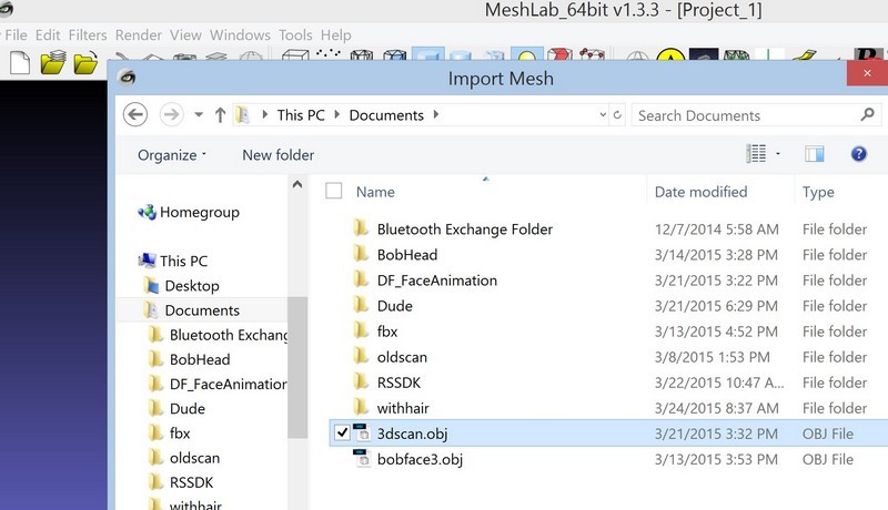
From the File menu, select Import. Select the 3Dscan.obj file located in the root of the Documents folder.
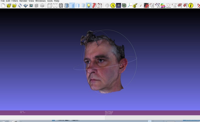
An imported object can be rotated to the side. You can left-click on the bottom of the object and drag to rotate the object and view it. You will see a grid with a colored texture. Color information is stored in the Vertex Colors format, that is, each vertex is painted with pixels in RGB colors received by the camera during scanning.
From the File menu, select Export Mesh As.
In the dialog box, select Stanford Polygon File Format (* .ply).
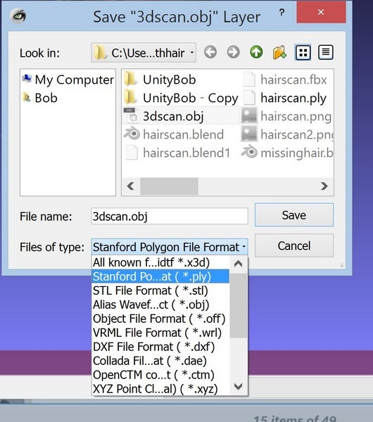
When saving, specify the path that you can then find.
Now you can go to work in Blender, where you can clean the grid and convert Vertex Colors to UV card format.
Vertex colors and UV map in Blender
The point is to import a three-dimensional model file and create a copy of it. Then you need to clear the copy and use the colors of the vertices as a UV map in the new version of the model.
Create a new project in Blender, select Import PLY and select the PLY file exported from MeshLab.

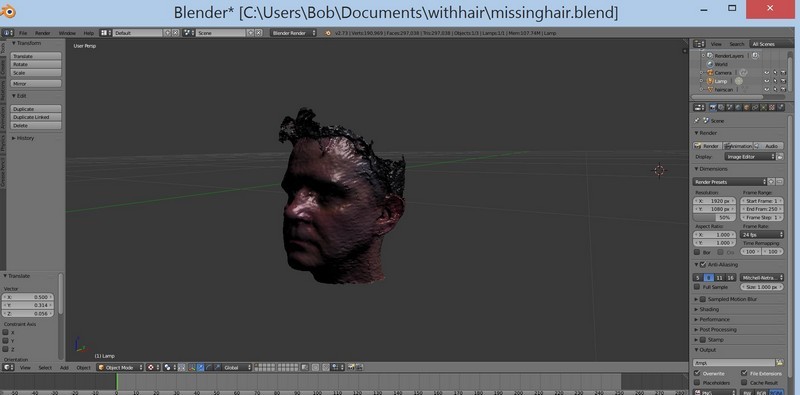
After import, you will see that there are no textures.
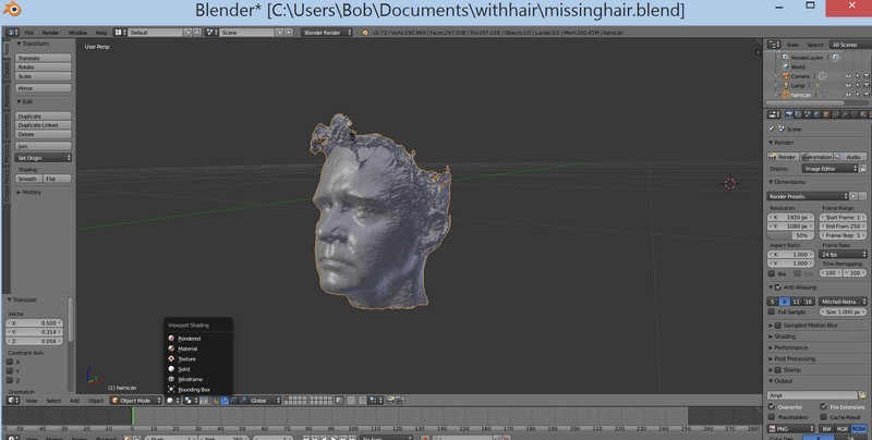
If you switch to the Texture view, you will see that the RGB colors from the scanned model are now mapped to the Texture mode.
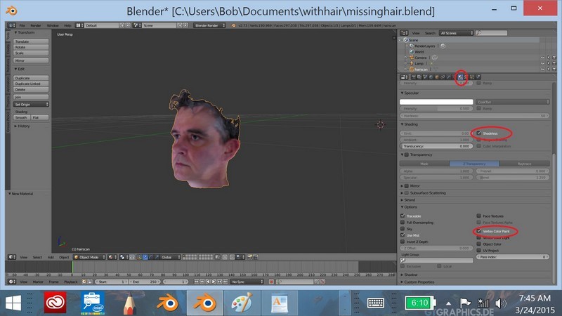
To display colors correctly, go to the Materials view. In the right pane, select the Materials icon. Create a new material. In the panel editor, set Shading to Shadeless, and in the Options section, select the Vertex Color Paint check box. The colors of the vertices will be assigned to the material of the object.
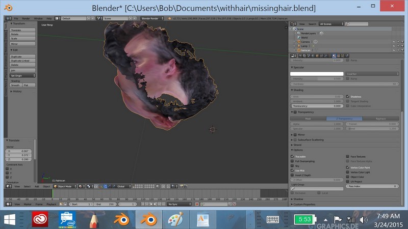
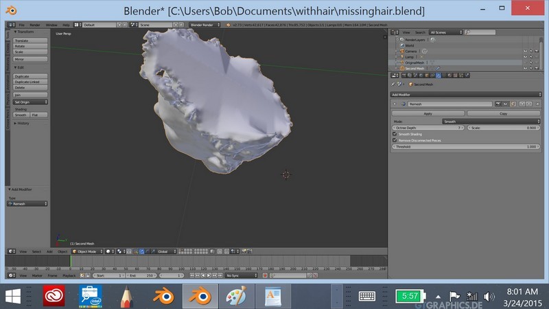
As you can see, you cannot work with such a model. It is full of holes, and the number of polygons far exceeds the desired. You need to create a version of this model that can be cleaned and present the texture with the colors of the vertices as a UV map. We are importing this version into Unity.
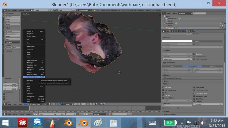
Duplicate the model
Go to the Object menu. Select Duplicate Mesh and press the Enter key. Do not move the mouse pointer.
Go to the Object menu, select Move To Layer and select the box on the right.

Go to the resource browser and rename the models. For example, let the first model be called the “original model” and the second “the second model”. This will help maintain order.
Select the second model, select the level to view, and switch the mode to Solid rendering.
Then click the Tool Wrench icon to add a modifier. We will change the number of polygons in the second model and, thus, make it cleaner.
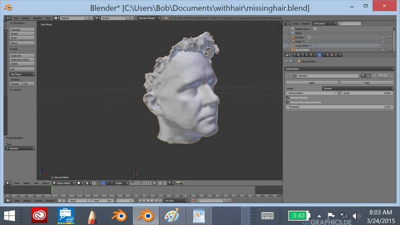
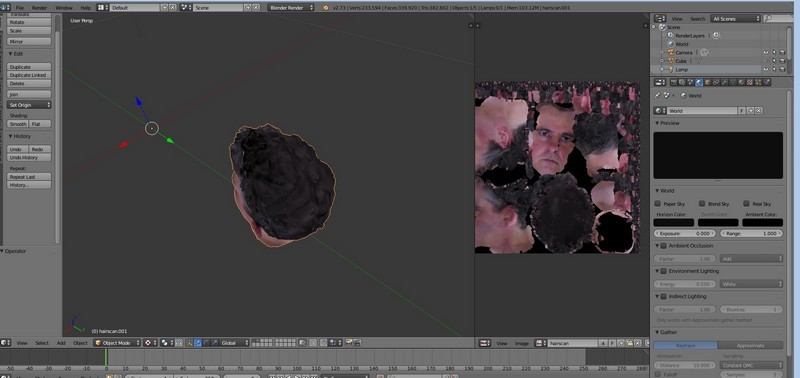
Select Remesh from the Tools menu. In the Remesh toolbox, specify a value between 7 and 8 for the Oct Tree parameter. Select the Smooth mode, check the Smooth Shading box. In this case, the comparison with the materials will disappear.
Click Apply. Now we have a cleaner model that you can apply vertex and UVMap to.
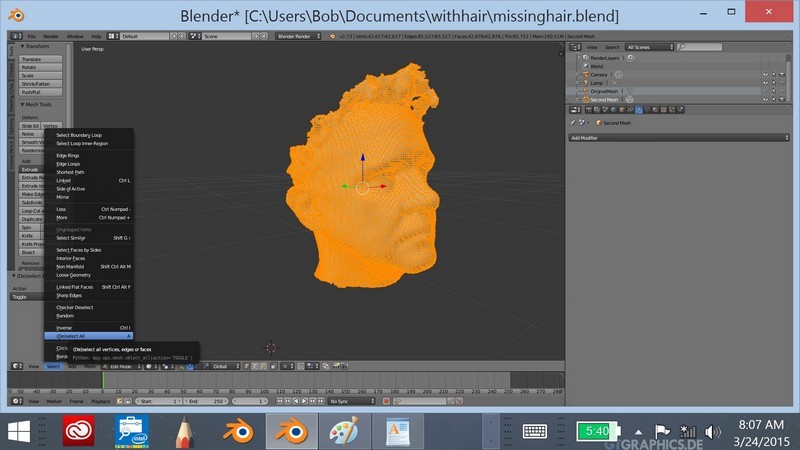
Switch to the editing mode of this second model. From the Select menu, select Select All.
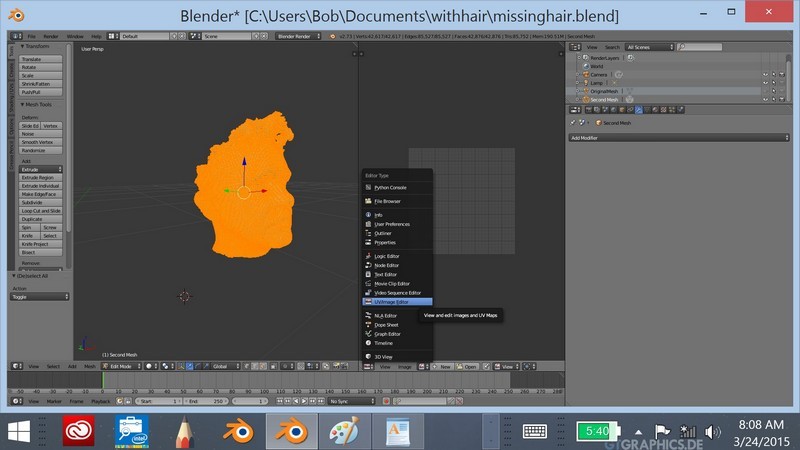
Create a new window and set it to UV Map mode to display UVMap.
In the 3D window, go to the Mesh menu and select UV.
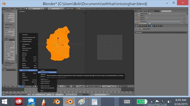
In the UV Map window, select NEW to create the texture. Uncheck Alpha. Specify the name of the model to be exported for the texture.
Switch to Object mode. You will see a black model and a black UV map. This is normal.
Now enable both layers with the Shift key.
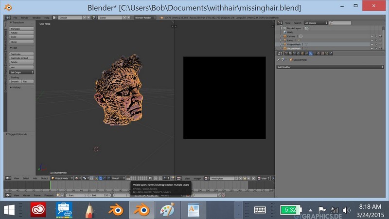
In Resource Explorer, select the original model.
Click the camera icon.
In the Bake area, select the Select to Active check box. Make sure the Bake to Vertex checkbox is unchecked.
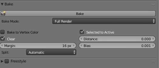
In the Scene section, set Color Management to None.

From the Asset menu, first select the original model. Then, while holding down the SHIFT key, select the second model. (Exactly in that order.) Both layers should be visible with the eye and camera icons turned on.
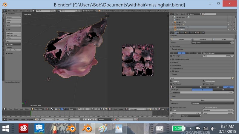
Click the camera icon. In the Bake section, click Bake.
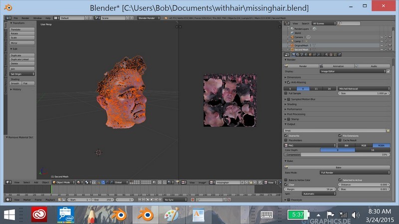
Now the texture should be mapped to the map. To verify this, turn off the first layer so that only the second model layer remains. Go to the Texture view and you will see a model on which the UV map will be overlaid as a texture.
Pay attention to some image instability in the missing parts of the model.
You can switch to Texture Paint mode and fix these flaws. Also now you can switch to Sculpt mode and fill in the missing places, clean the model or add new elements to it. Now the model is ready, it can be exported. And the last thing to keep in mind.
- Make sure that the UVMap map has the same name and is in the same folder as the model.
- Go to the UVMap window, select Save As from the Image menu and select the folder where you want to save the model.
- Then go to the File menu and export the file to .FBX format, giving the same name as for the UV map.
Now you are ready to import this 3D model into Unity.
Import files into Unity
After completing the steps of the previous part, you should have got a model in .FBX format with a UV-map texture.
Open Unity (Unity 5 is available as a free download).
Create a new project and scene.
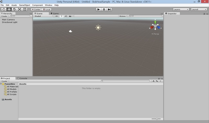
From the Assets menu, select Import new asset. Select the model in .FBX format that you exported from Blender.
When importing an object, it is quite possible that its texture is not imported.
In this case, you will see a light gray version of the grid. This is normal. Now we will add a texture map.

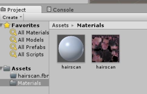
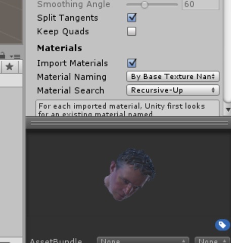
Select the Materials folder, right-click and select Import Asset. Select the PNG file that you saved in Blender and import it.
You will now see a texture map next to the gray material. Right-click on the gray material in the shape of a ball, whose name matches the name of your grid, and delete the material.
Go back to the Assets folder and right-click on the grid you imported. Select Reimport.
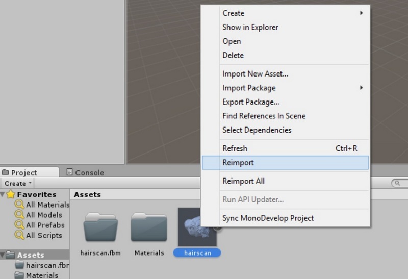
After re-importing the material is created correctly and the grid is displayed with the desired texture.

If the model is displayed in pink in the viewport, simply select another object, such as a camera, and then select your grid again. Now it should display correctly.
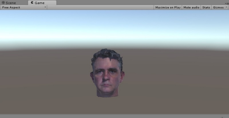
Now the object is ready for use. Drag the object to the scene. You can enlarge it and adjust the camera to get the desired view.
Moving the camera, you should see your object correctly displayed in Unity.
Finally, if you want to edit the texture, for example to make it more or less shiny, go to the Materials folder and select the spherical version of your texture. In the Inspector window, you can edit the degree of reflection and smoothness to get the desired appearance of the texture.
Good luck and wait for your comments! You can also find me on Twitter: @bobduffy.