May 29, 2015 at 14:19
Visualization of sound on a 6E1P lamp
I decided to share the experience of creating a sound indicator on a 6E1P lamp. When creating a tube audio amplifier for headphones, it was decided to visualize the audio signal. The choice fell on this particular Soviet lamp. The result was a small printed circuit board measuring 30x33 mm. This article provides a diagram of this board and a description of the operation algorithm.
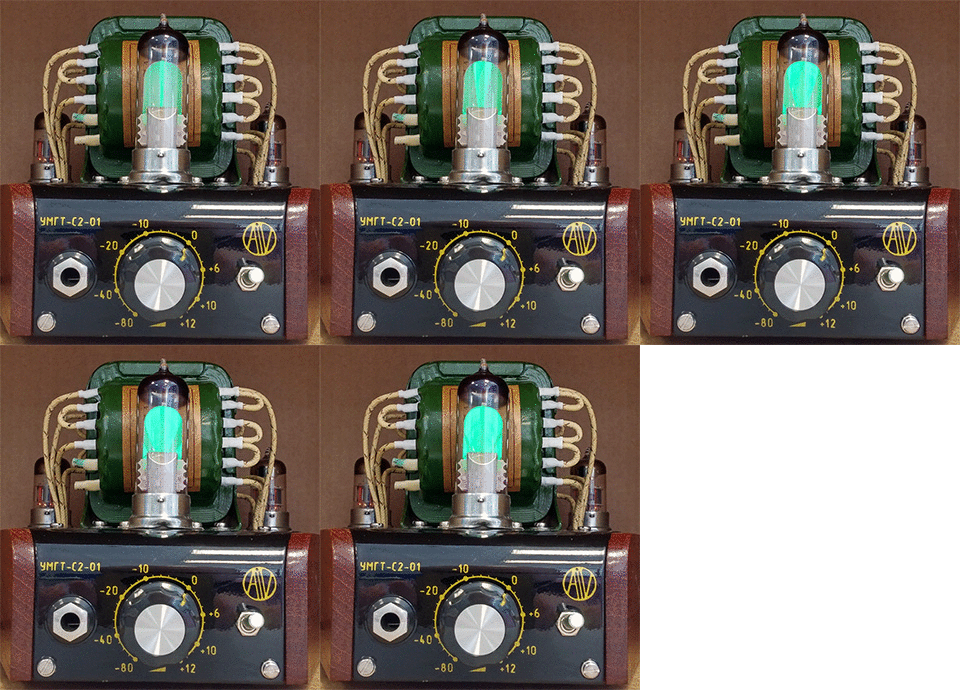
The 6E1P lamp is not scarce and relatively easy to get at a price of about 200 rubles. This article will not address the issues of creating an audio amplifier and the quality of audio sound , we will only discuss the connection and control of the 6E1P lamp. Anyone can repeat my scheme, modify or use individual nodes of the scheme in their devices (source codes are attached).
When creating a tube amplifier, it was decided to decorate and make the appearance of the tube headphone amplifier more vibrant due to the animation of the sound signal. The amplifier itself is assembled on two 6N23P dual triodes according to the SRPP cascade scheme . The design of the amplifier repeats the trapezoid: 6N23P lamps are located at the rear, a 6E1P lamp is located at the front. Read more about the amplifier here .
As an introduction, I will give the main points that were at the time of the beginning of the development of the lamp control circuit, and determined the final implementation:
It is believed that in tube audio technology it is not beautiful to use integrated circuits. I have no such prejudice and, as was written above, in this article the quality of the audio signal is not discussed. It will be exclusively about the scheme of high-quality lamp control 6E1P.
Let's get started!
The 6E1P lamp uses a standard filament and anode voltage.
Glow: 6.3V / 300 mA -> 1.9 W
Anode: 250V / 6 mA -> 1.5 W
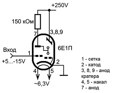
In my project I used TAN 21-127 / 220-50 to power the 6E1P lamp, the rest of the amplifier tubes and the microcontroller . In the final circuit, an anode voltage of + 270V was used.
Read more about TAN transformers here .
If you aim only at visualization, then using TAN may not be practical. It would be more reasonable to use network power adapters with the subsequent formation of high voltage, glow voltage and controller power using switching power supplies. For example, this option is used for discharge lamps in a Nixie tube clock.
I would recommend choosing a 24V network adapter. This will make the boost converter circuit easier and more efficient and will make virtual ground for the lamp (see below).
Now about connecting the lamp. The terminals of the glow (4 and 5) of the 6E1P lamp are isolated from the other terminals of the lamp, so you can connect them as you like, the main thing is that there is a voltage of about 6V between them. Permanent possible, variable possible. Only if TAN is used, it is recommended to pull conclusions 4 and 5 to terminal 2 (ground) to avoid breakdown between the filament and the cathode. Pins 3, 7, 8, 9 are connected to high voltage. And now, the most interesting - pin 1 (grid) controls the opening of the lamp using negative voltage! A voltage of -12 ... -15V on the grid relative to the cathode corresponds to a full opening of the lamp, and a voltage of 0 to full closure. And even worse, in reality, when the grid is grounded to the cathode, the lamp does not completely close: instead of a thin, even luminous strip, there is a greasy luminous cone. This is solved by applying a small positive voltage to the grid (+ 5V is enough). Thus, the lamp is controlled by voltage relative to the cathode from -15V to + 5V. Which, to put it mildly, is inconvenient.
Let's move on to the audio signal conversion circuit. The audio channel must provide the summation of the signal from two channels and bring it to the input range of the ADC controller (the signal amplitude is not more than 5V).
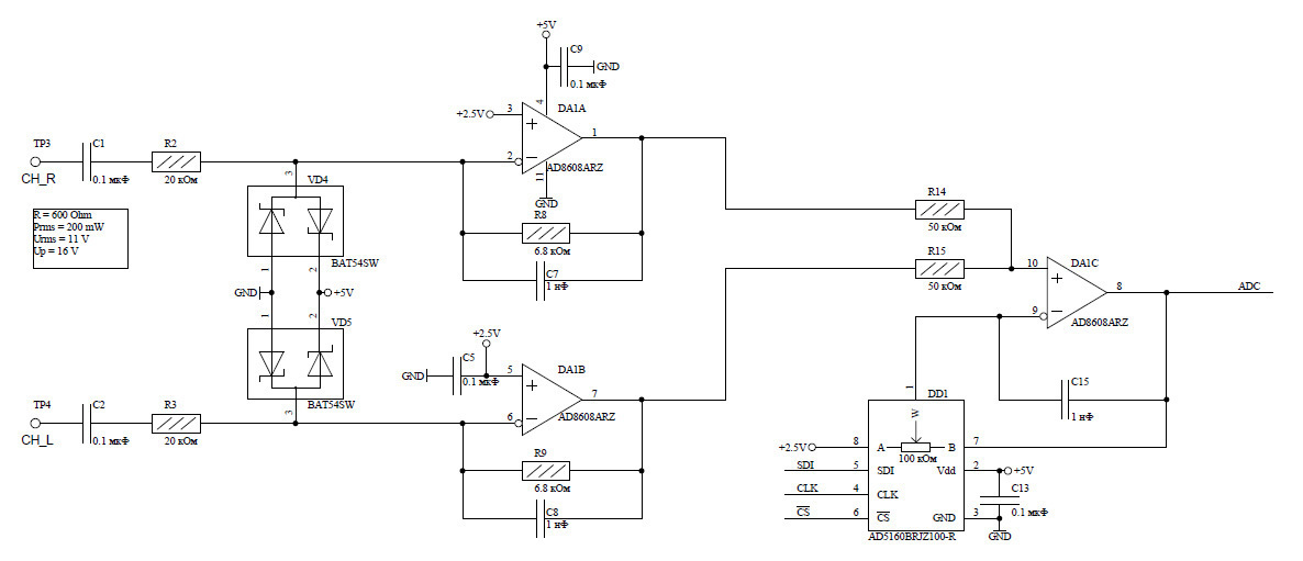
We have two channels. Since any circuit when connected introduces distortion into the original signal, and the amplifier output is the least sensitive to this, we connect directly to the amplifier output (in parallel with the load, to the headphones). The signal is permanently decoupled by 0.1 μF input capacitors. Diodes VD4 and VD5 are used to protect the circuit from possible input spikes. Further, on each channel, there is an inverting amplifier (DA1A and DA1B) with a gain of 0.34. They perform 2 tasks. Firstly, for high-impedance headphones, they reduce the signal amplitude by 3 times, leading it to the 5V range. Since, for example, for 600 Ohm headphones, the signal amplitude can be up to 16V. Secondly, they serve as buffer amplifiers for the subsequent adder. If they were not there, and immediately send the signal to the adder, then, in fact,
Next, the signal is fed to the adder and amplifier with auto-tuning (DA1C). The gain can vary from 1 to 1000. The AD5160 digital potentiometer is one of the most readily available and cheapest. It has 256 positions. Amplifier selected AD8608 in quadruple package. The last fourth amplifier (DA1D) used to create a + 2.5V virtual ground:

In principle, a similar circuit could be made for a + 21V virtual ground.
ATiny25 / 45 is selected as the microcontroller. Sufficient performance for this task, 5V power, small housing. Typically, programming the AVR8 family of controllers is simple and intuitive, but the ATiny25 / 45 is an ultra-low integration controller and contains almost no hardware blocks. Therefore, working with the ATiny25 / 45 universal transceiver is not pleasant: almost everything has to be done programmatically.

The 6E1P lamp control circuit itself is built on the IRLML2803 field-effect transistor and is a simple PWM with an low-pass filter. The transistor switches the voltage + 28V or ground. Regarding the output of 2 lamps, this will be + 7V or -21V.
Also in my device, I decided to add a miniature dual relay to switch. With it, I switch the anode voltage of the amplifier after warming up the lamps and control the LED in the power switch, changing its color from red to green after warming up. There is one feature: the controller’s PB5 port is used as RESET and is not available until the corresponding FUSE bit is flashed, but after flashing it will become impossible to program through SPI. So we activate the PB5 port in the very least, when everything is debugged and works as it should.
As a result of lengthy experiments with various methods of processing an audio signal and selecting various parameters, an optimal option was found that gives good visualization. Anyone can develop their own regulation algorithm, which will be better suited to their hardware solution or listening to music content.
My method includes: preliminary filtering the signal, determining the local maximums of the signal, generating a lamp control signal, controlling the gain of the amplifier.
Now, in order, I will describe the operation of the algorithm.
Actual oscilloscope measurements showed that the algorithm, on average, updates PWM data at a frequency of 1 kHz. The frequency swims a lot and depends on the differences in the amplitude of the input signal. But, in any case, the PWM data is updated at least with a frequency of 100 Hz, which is enough for good visualization. The gain changes from 2 to 10 times per second.
The microcontroller firmware project (ATiny45) for IAR v6.3 and the wiring diagram for Altium Designer 2009 are located at:
https://bitbucket.org/AiV_Electronics/6e1p_tube/overview
The lamp responds well to both high-frequency and low-frequency sounds. It fulfills clearly, without delay. The magnitude of the reaction is adequate to the sound volume. On this I consider the task solved.
I want to note that, although this option is final and it is not planned to further refine it, nevertheless, this version leaves room for improvement. If the task of refinement confronted me, I would improve the circuit in the following moments:
That's all for now. In the future I plan to write an article on the manufacture of the mechanical part of the amplifier and share the experience of manufacturing REA cases from wood, manufacturing parts from sheet metal, painting, varnishing and marking through stencils and stamps.
Thanks for attention. Waiting for your questions and comments.
PS I’m worried in advance that the topic could develop into a discussion of tube audio technology and audio quality issues. Therefore, I ask you to discuss exclusively issues related to the visualization of the audio signal. Thanks in advance.
The 6E1P lamp is not scarce and relatively easy to get at a price of about 200 rubles. This article will not address the issues of creating an audio amplifier and the quality of audio sound , we will only discuss the connection and control of the 6E1P lamp. Anyone can repeat my scheme, modify or use individual nodes of the scheme in their devices (source codes are attached).
Photograph of a lamp and designed board

Content:
- Introduction
- Part 1. Power and lamp connection
- Part 2. Analog channel circuitry
- Part 3. Management scheme
- Part 4. Control Algorithm
- Part 5. Result
INTRODUCTION
When creating a tube amplifier, it was decided to decorate and make the appearance of the tube headphone amplifier more vibrant due to the animation of the sound signal. The amplifier itself is assembled on two 6N23P dual triodes according to the SRPP cascade scheme . The design of the amplifier repeats the trapezoid: 6N23P lamps are located at the rear, a 6E1P lamp is located at the front. Read more about the amplifier here .
Amp photo (large)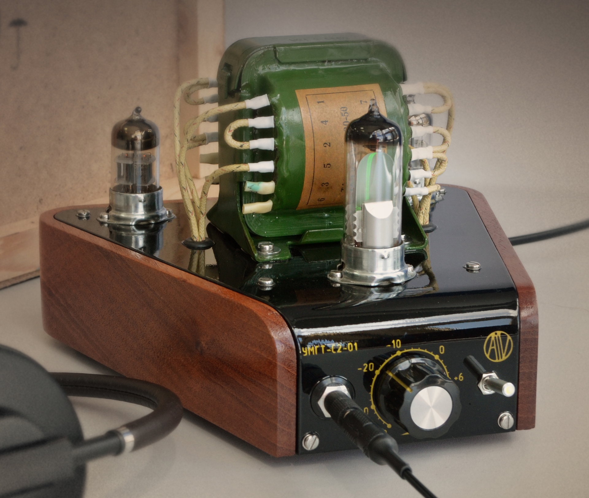
As an introduction, I will give the main points that were at the time of the beginning of the development of the lamp control circuit, and determined the final implementation:
- The 6E1P lamp glows with a pleasant green light and looks original among many other lamp indicators of the past. The lamp is mounted vertically, which is much more convenient than end lamps, especially when used in conjunction with other vacuum tubes in an amplifier, which are typically mounted vertically on the top panel.
- The required supply voltages are combined with the supply voltages of other vacuum tubes, which does not require a separate power supply. True, there is some peculiarity at this point (see below).
- Immediately the task was to draw a joint audio signal from two channels to one 6E1P lamp. It is usually placed on each channel in its own indicator lamp or use the output of only one of the stereo channels for visualization. Here, from the very beginning, the task was to make an “honest” display of the audio signal.
- The solution to point 3 requires a signal adder, which, of course, can be implemented on vacuum tubes, but then the control circuit of the indicator lamp will equal in complexity with the circuit of the amplifier itself. The classic 6E1P lamp switching circuitry provides for removing a signal either from the anode of the output lamp of the amplifier, or using a special matching transformer, which is much more difficult to get than the 6E1P lamp itself. Also, classical schemes do not provide automatic adjustment of the signal amplitude, which leads to a dependence of the degree of opening of the lamp on the volume level. This dependence is critical when using headphones, as headphone impedance can vary between 32-600 Ohms, which gives a change in the amplitude of the output signal by a factor of ten. Therefore, it was immediately decided: to use integrated amplifiers; to implement auto-tuning, use a digital potentiometer controlled by a microcontroller; digitally filter the audio signal by the controller.
It is believed that in tube audio technology it is not beautiful to use integrated circuits. I have no such prejudice and, as was written above, in this article the quality of the audio signal is not discussed. It will be exclusively about the scheme of high-quality lamp control 6E1P.
Let's get started!
PART 1. POWER AND LAMP CONNECTION
The 6E1P lamp uses a standard filament and anode voltage.
Glow: 6.3V / 300 mA -> 1.9 W
Anode: 250V / 6 mA -> 1.5 W
In my project I used TAN 21-127 / 220-50 to power the 6E1P lamp, the rest of the amplifier tubes and the microcontroller . In the final circuit, an anode voltage of + 270V was used.
Read more about TAN transformers here .
If you aim only at visualization, then using TAN may not be practical. It would be more reasonable to use network power adapters with the subsequent formation of high voltage, glow voltage and controller power using switching power supplies. For example, this option is used for discharge lamps in a Nixie tube clock.
I would recommend choosing a 24V network adapter. This will make the boost converter circuit easier and more efficient and will make virtual ground for the lamp (see below).
Now about connecting the lamp. The terminals of the glow (4 and 5) of the 6E1P lamp are isolated from the other terminals of the lamp, so you can connect them as you like, the main thing is that there is a voltage of about 6V between them. Permanent possible, variable possible. Only if TAN is used, it is recommended to pull conclusions 4 and 5 to terminal 2 (ground) to avoid breakdown between the filament and the cathode. Pins 3, 7, 8, 9 are connected to high voltage. And now, the most interesting - pin 1 (grid) controls the opening of the lamp using negative voltage! A voltage of -12 ... -15V on the grid relative to the cathode corresponds to a full opening of the lamp, and a voltage of 0 to full closure. And even worse, in reality, when the grid is grounded to the cathode, the lamp does not completely close: instead of a thin, even luminous strip, there is a greasy luminous cone. This is solved by applying a small positive voltage to the grid (+ 5V is enough). Thus, the lamp is controlled by voltage relative to the cathode from -15V to + 5V. Which, to put it mildly, is inconvenient.
Power scheme
And so, the power supply circuit of the microcontroller (+ 5V) is as follows:

One of the TAN windings at ~ 20V was used. Assembled rectifier at + 28V. Used chip low-power pulse generator TPS62120. The microcircuit was available and has small dimensions, so the choice fell on it, but it has a maximum input voltage of 15V. Therefore, the voltage from 28V to 15V drops at the limiting resistor R4 and additionally protects the zener diode at 15V. I can not recommend such a hybrid power supply for repetition, but, nevertheless, it works stably for a current of 10 mA. Having a zener diode, it is better to assemble a parametric stabilizer .
I use + 28V voltage to control the lamp. Voltage + 5V is used to power the rest of the board (amplifiers, microcontroller, potentiometer).
To control the lamp, we create a virtual ground + 21V as follows:

We use the + 28V power supply and, using a 21V zener diode, create a virtual ground AMP_GND at + 21V. It is this virtual earth that needs to be connected to the output of 2 lamps. This can be done because all the windings of the TAN are isolated, and the ground of the board is not connected to the ground of the lamp supply (+ 250V). Then to control the lamp we get the voltage range from -21V to + 7V.
If you use power from a 24V network adapter and generate a high voltage with a pulsed source, then form a virtual earth of about 18V with the same exact circuit (replacing the zener diode with 18V).
One of the TAN windings at ~ 20V was used. Assembled rectifier at + 28V. Used chip low-power pulse generator TPS62120. The microcircuit was available and has small dimensions, so the choice fell on it, but it has a maximum input voltage of 15V. Therefore, the voltage from 28V to 15V drops at the limiting resistor R4 and additionally protects the zener diode at 15V. I can not recommend such a hybrid power supply for repetition, but, nevertheless, it works stably for a current of 10 mA. Having a zener diode, it is better to assemble a parametric stabilizer .
I use + 28V voltage to control the lamp. Voltage + 5V is used to power the rest of the board (amplifiers, microcontroller, potentiometer).
To control the lamp, we create a virtual ground + 21V as follows:
We use the + 28V power supply and, using a 21V zener diode, create a virtual ground AMP_GND at + 21V. It is this virtual earth that needs to be connected to the output of 2 lamps. This can be done because all the windings of the TAN are isolated, and the ground of the board is not connected to the ground of the lamp supply (+ 250V). Then to control the lamp we get the voltage range from -21V to + 7V.
If you use power from a 24V network adapter and generate a high voltage with a pulsed source, then form a virtual earth of about 18V with the same exact circuit (replacing the zener diode with 18V).
PART 2. ANALOGUE CHANNEL DIAGRAM
Let's move on to the audio signal conversion circuit. The audio channel must provide the summation of the signal from two channels and bring it to the input range of the ADC controller (the signal amplitude is not more than 5V).
We have two channels. Since any circuit when connected introduces distortion into the original signal, and the amplifier output is the least sensitive to this, we connect directly to the amplifier output (in parallel with the load, to the headphones). The signal is permanently decoupled by 0.1 μF input capacitors. Diodes VD4 and VD5 are used to protect the circuit from possible input spikes. Further, on each channel, there is an inverting amplifier (DA1A and DA1B) with a gain of 0.34. They perform 2 tasks. Firstly, for high-impedance headphones, they reduce the signal amplitude by 3 times, leading it to the 5V range. Since, for example, for 600 Ohm headphones, the signal amplitude can be up to 16V. Secondly, they serve as buffer amplifiers for the subsequent adder. If they were not there, and immediately send the signal to the adder, then, in fact,
Next, the signal is fed to the adder and amplifier with auto-tuning (DA1C). The gain can vary from 1 to 1000. The AD5160 digital potentiometer is one of the most readily available and cheapest. It has 256 positions. Amplifier selected AD8608 in quadruple package. The last fourth amplifier (DA1D) used to create a + 2.5V virtual ground:
In principle, a similar circuit could be made for a + 21V virtual ground.
PART 3. MANAGEMENT SCHEME
ATiny25 / 45 is selected as the microcontroller. Sufficient performance for this task, 5V power, small housing. Typically, programming the AVR8 family of controllers is simple and intuitive, but the ATiny25 / 45 is an ultra-low integration controller and contains almost no hardware blocks. Therefore, working with the ATiny25 / 45 universal transceiver is not pleasant: almost everything has to be done programmatically.
The 6E1P lamp control circuit itself is built on the IRLML2803 field-effect transistor and is a simple PWM with an low-pass filter. The transistor switches the voltage + 28V or ground. Regarding the output of 2 lamps, this will be + 7V or -21V.
Also in my device, I decided to add a miniature dual relay to switch. With it, I switch the anode voltage of the amplifier after warming up the lamps and control the LED in the power switch, changing its color from red to green after warming up. There is one feature: the controller’s PB5 port is used as RESET and is not available until the corresponding FUSE bit is flashed, but after flashing it will become impossible to program through SPI. So we activate the PB5 port in the very least, when everything is debugged and works as it should.
PART 4. MANAGEMENT ALGORITHM
As a result of lengthy experiments with various methods of processing an audio signal and selecting various parameters, an optimal option was found that gives good visualization. Anyone can develop their own regulation algorithm, which will be better suited to their hardware solution or listening to music content.
My method includes: preliminary filtering the signal, determining the local maximums of the signal, generating a lamp control signal, controlling the gain of the amplifier.
Now, in order, I will describe the operation of the algorithm.
- The total signal of both channels is read by the ADC with the maximum sampling frequency for this microcontroller - 77kSPS.
- The signal is filtered. A simple method of calculating the average of 4 samples was applied. Thus, we reduce the sampling rate to 19.2kSPS.
- The signal is variable with a constant component + 2.5V (0x7f). We straighten it (subtracting 0x7f) and remove the noise near zero.
- 5 accumulated counts (averaged) are used to search for a local maximum (peak) using a sliding window, which reduces the frequency bandwidth to about 2.4 kHz.
- We adjust the PWM output to the lamp, depending on the peak value obtained. I introduced regulation with an asymmetric restriction. Those. I increase the PWM with a large step, and decrease it with a small one.
- Adjust the gain using a digital potentiometer. I propose the following algorithm for regulation:
- a) Find the maximum of all peaks in a certain time interval. In my version, on average, this interval is about 300ms.
- b) If in this interval the maximum peak is more than 90% of the input range, then reduce the gain.
- c) If in this interval the maximum peak is less than 50% of the input range, then increase the gain.
- d) The proposed analog circuit has the following drawback: the regulation of the gain is nonlinear due to the applied method of turning on the potentiometer. Especially strong nonlinearity at high gain, i.e. a change in the potentiometer by one step leads to a multiple increase in gain and, as a result, to an overload of the ADC input. Therefore, I had to abandon the use of the last few steps of the potentiometer (254 and 255), and instead amplify the signal by simply multiplying it by 2 ÷ 8.
Actual oscilloscope measurements showed that the algorithm, on average, updates PWM data at a frequency of 1 kHz. The frequency swims a lot and depends on the differences in the amplitude of the input signal. But, in any case, the PWM data is updated at least with a frequency of 100 Hz, which is enough for good visualization. The gain changes from 2 to 10 times per second.
The microcontroller firmware project (ATiny45) for IAR v6.3 and the wiring diagram for Altium Designer 2009 are located at:
https://bitbucket.org/AiV_Electronics/6e1p_tube/overview
PART 5. RESULT
Video with the result of the lamp for different musical compositions
The lamp responds well to both high-frequency and low-frequency sounds. It fulfills clearly, without delay. The magnitude of the reaction is adequate to the sound volume. On this I consider the task solved.
I want to note that, although this option is final and it is not planned to further refine it, nevertheless, this version leaves room for improvement. If the task of refinement confronted me, I would improve the circuit in the following moments:
- I would change the circuit of the power source to a fully pulsed one. I wouldn’t put a linear stabilizer, because transformer winding only 47mA.
- I would change the switching scheme of the potentiometer to eliminate non-linearity.
- I would use a parametric stabilizer to form a virtual earth + 21V and reduce the capacitors C18-C20.
That's all for now. In the future I plan to write an article on the manufacture of the mechanical part of the amplifier and share the experience of manufacturing REA cases from wood, manufacturing parts from sheet metal, painting, varnishing and marking through stencils and stamps.
Thanks for attention. Waiting for your questions and comments.
PS I’m worried in advance that the topic could develop into a discussion of tube audio technology and audio quality issues. Therefore, I ask you to discuss exclusively issues related to the visualization of the audio signal. Thanks in advance.