Homemade test bench for motherboards
I think that, sooner or later, everyone who regularly picks with computer hardware comes up with the idea of somehow optimizing the workplace - every time they bother to lay out on the table, then clean up. Plus, sometimes fussing with the motherboard can go a few days, but during this time you may need to do something else on the table, even start something else, etc. And if the motherboard is decomposed there, and even some tests go, then it may be undesirable to move it. So the classic “box for the motherboard” stops arranging. It came to me rather late than early, but it is better than never :)

At first, of course, I went to see the finished options. They are, but they are quite expensive, even Chinese. The average price is around $ 100, there is cheaper, there is more.
Alpha-DB6 Case . In principle, not such an expensive option, if the delivery is not considered. Single-storey with a "basement" for drives.

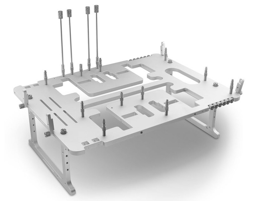
BC1 Open Benchtable (In general, this is a rather interesting project and there are drawings for independent production on the site ).
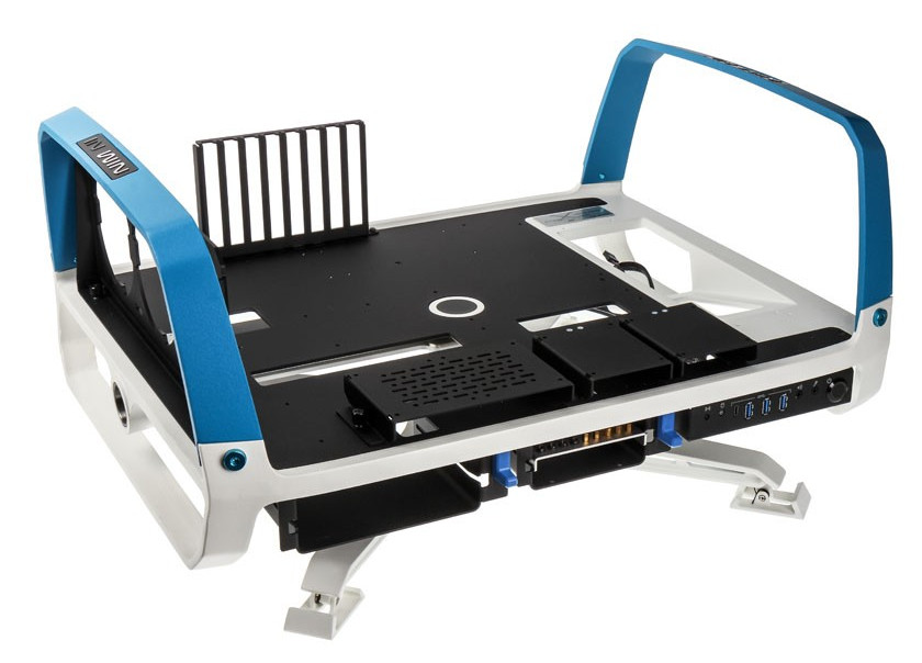
X-frame 2.0 . I do not know why they are asking for that kind of money.
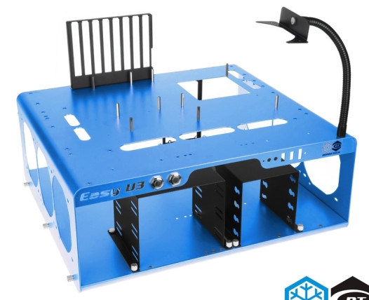
Bench / Test Table Easy V3.0 .
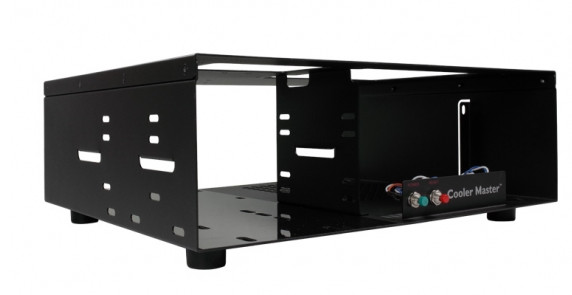
Test Bench V1.0 . Only functionality, what's there, what's the option above.
QDIY PC-D60. Chinese version. There is a bare base under the motherboard, only mATX and less, the PSU is installed on the side, there is no space for an optical drive.

I consulted with the toad and decided that I would not buy anything. You have to do it yourself. I looked at what the Internet can advise on this topic. The Internet has advised a lot of things, not the first one I wanted.
General ideas - a two-tier design, on the lower "floor" is the power supply and storage media, on the top - the motherboard. There are single-tier options when the power supply unit and the drives next to the motherboard are located, but they take up more space on the table.
Most of them make a stand from an old case - they take out a tray for the motherboard from there, make a frame from the remains of the case, then fix the tray from above.
When choosing options, I proceeded from the following things:
I chose wood as the material for the base - it is easier to work with it, it forgives more mistakes. Which I will have.
To attach the motherboard unscrew the tray from the old case. It would be possible to install fastenings directly on the stand base, but this is extra work - everything is already marked on the pallet under the standard dimensions of the mainboard, and fastening it with four screws to the base is much easier than installing a dozen racks for different types of mainboards. The pallet from the old Invin would be ideal (the A-series, in my opinion, the early ATX, where the pallet on the rails, along with the motherboard, was pushed out of the hull). But, unfortunately, I didn’t have anything like that at hand. Yes, and it would be a pity to cut a good body. And I used some kind of can of superpover type.
Booth size is chosen based on the size of the pan - slipped on a pair of centimeters on each side, somewhat rounded - turned 30x40 cm height is equal to the power supply unit height, supplied upright -. 15 cm.
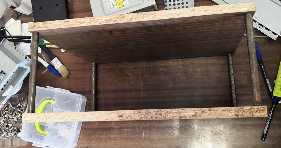
Then I somewhat cheated - did not do himself, and went to the locksmith and to the carpenters and said “I need such a damn thing.” In the end, after a couple of weeks (they were busy, but I did not burn) received the ordered shitty.
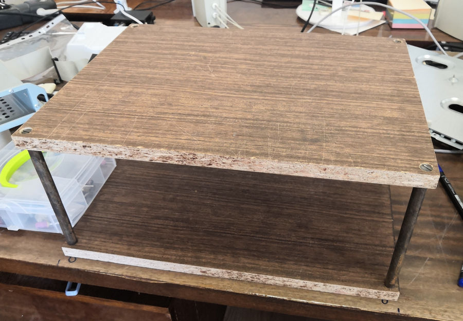
Two pieces of chipboard, legs made of metal tubes. I myself, most likely, would have made wooden legs - I would take a handle from a mop and cut off four pieces of the required length, then put it on long screws.
The power supply was thinking how to install - vertically or horizontally, in the end it was set horizontally. Anyway, the length of the processor power cable was not enough so that it was, and the rest of the wires were more convenient to use with a horizontal power supply. Fixed BP just two corners. The power supply itself is the usual five hundred. Of course, it would be ideal to put a power supply unit with detachable wires here, but what I used as a bench power supply unit is what I plugged in.

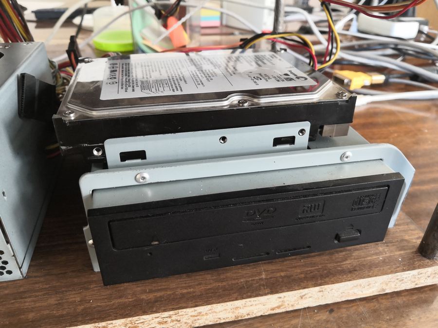
To mount optical drives and disks, I took a rack from another old case, which is convenient because it has a couple of stops for the hard disk and does not have to be screwed on for reliable fastening. But the drive must be fixed.

The motherboard tray was screwed with five bolts, after the final choice of the place I cut a couple of holes for the cables to pass through.

For quick attachment of the motherboard, I put several “pegs” (just screw the bolts from the bottom), only in one place I left a bolt with a lamb under the twisting fingers.

The rest of the racks are either plastic or with plastic plugs - so that motherboards can fit on them without fear of closing something - not all boards have mounting holes in standard places. The lining is glued for the same purpose - AT mothers in this place hang in the air and, in principle, can bend down to the metal (although I have no pure AT motherboard, but AT / ATX are found).
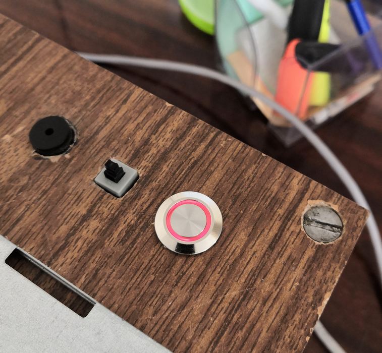
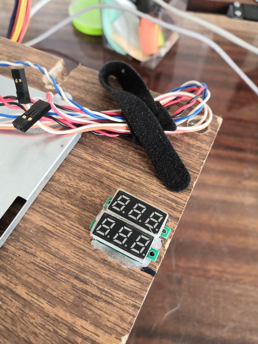
Sideways left room for whistles and lights. On the one hand, the power button with a luminous rim - I connect it to the hard disk activity, the Reset button and the speaker. Drilled holes of the appropriate diameter and put it on the glue from the gun.

The power supply LED decided not to dissolve, instead of it I put two voltmeters - 5 and 12 volts. The voltmeters are penny, the second decimal place is set to noodle, but you can approximately control the voltage, the drawdown to 11 volts can be seen. If you need more precisely, that is a multimeter. Well, the power indicator earn additionally. So far from the buttons set aside in order to make it easier to take his hands for carrying. Also put on a hot melt glue, although it could be screwed. In the corner, I attached a reusable tie to secure the wires from the buttons in the “free time”.
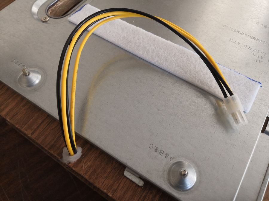
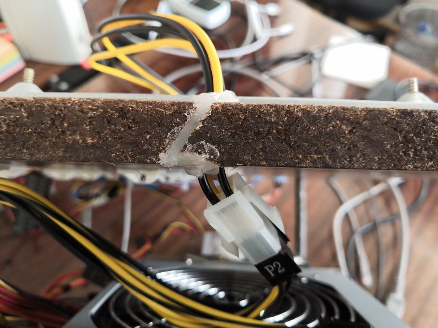
The insufficient length of the power cable of the processor was decided by gluing the extension cord. The cable from the power supply unit connects to it from below, and on top of the length it is enough to reach almost any place around the socket.
Along the far edge I made several additional slots for the passage of cables, closed three, left one open. But no one bothers and closed open if necessary.
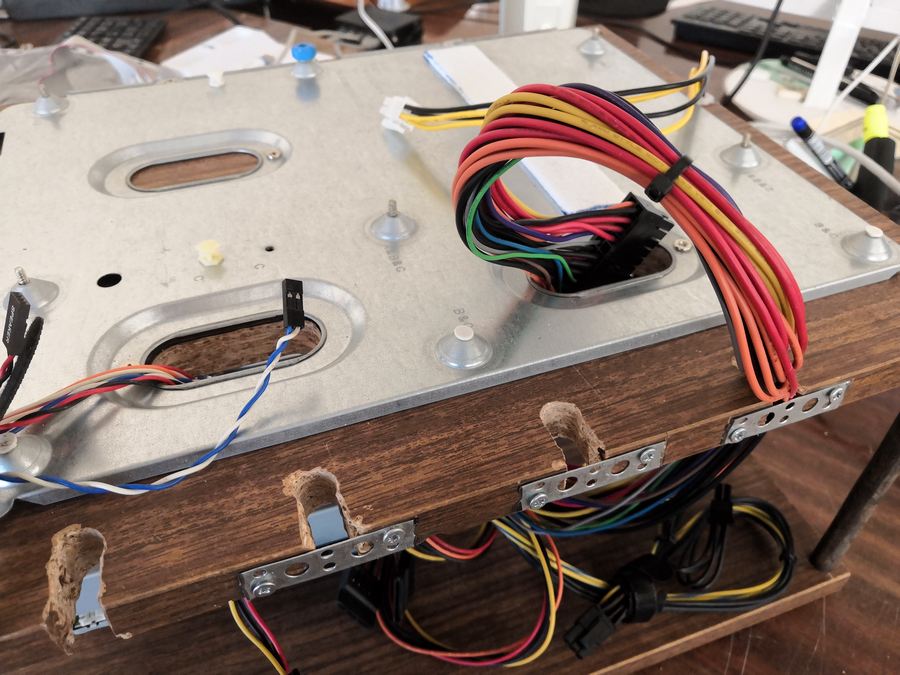
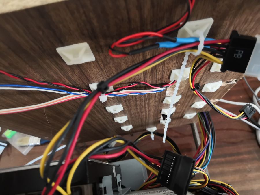
From the bottom, “on the ceiling,” hung out areas for fastening the screeds, so that the wires were more convenient to be laid-hung. Not everything has been hung yet, the construction has been assembled not so long ago, it has not settled down completely.
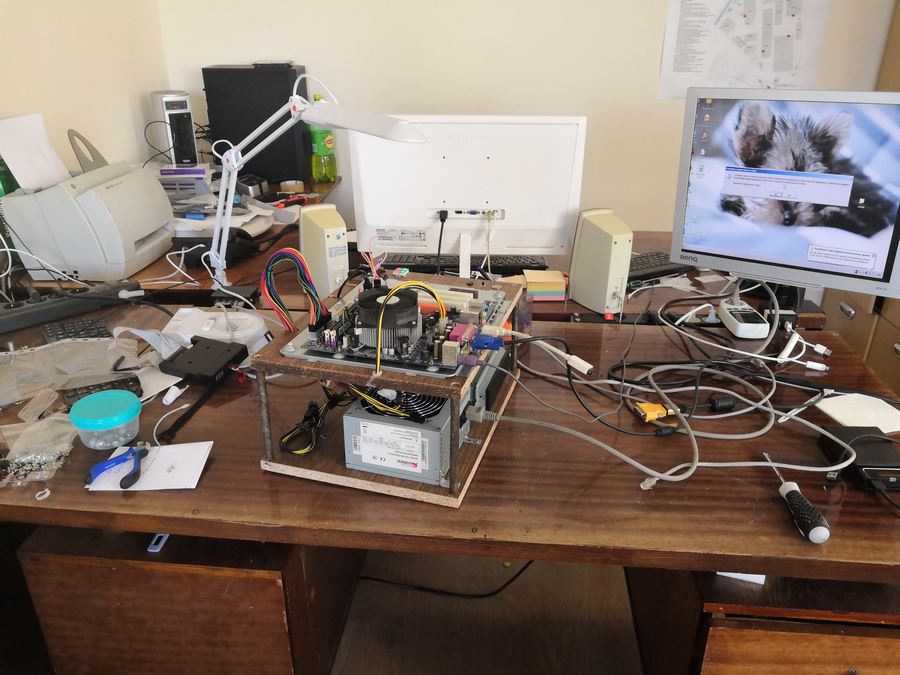
Well, everything, in principle, can be used. Outwardly, of course, the collective farm, but its tasks.


From planned improvements:
From unplanned, but thought out improvements - the supporting frame for expansion cards. Still not sure if I need it here - boards rarely cost more than one or two pieces and they normally hold in slots.
Of course, there will certainly be a lot of comments on the topic “And aren't you ashamed to put such a collective farm on public display? There would be no first polished and painted in a fun color. And the cat drew! ”
No, not ashamed. Because I am aware that this is a collective farm, but I did not find much Russian materials on the subject of creating such stands. Let it be one more.
At first, of course, I went to see the finished options. They are, but they are quite expensive, even Chinese. The average price is around $ 100, there is cheaper, there is more.
Alpha-DB6 Case . In principle, not such an expensive option, if the delivery is not considered. Single-storey with a "basement" for drives.
BC1 Open Benchtable (In general, this is a rather interesting project and there are drawings for independent production on the site ).
X-frame 2.0 . I do not know why they are asking for that kind of money.
Bench / Test Table Easy V3.0 .
Test Bench V1.0 . Only functionality, what's there, what's the option above.
QDIY PC-D60. Chinese version. There is a bare base under the motherboard, only mATX and less, the PSU is installed on the side, there is no space for an optical drive.
I consulted with the toad and decided that I would not buy anything. You have to do it yourself. I looked at what the Internet can advise on this topic. The Internet has advised a lot of things, not the first one I wanted.
General ideas - a two-tier design, on the lower "floor" is the power supply and storage media, on the top - the motherboard. There are single-tier options when the power supply unit and the drives next to the motherboard are located, but they take up more space on the table.
Most of them make a stand from an old case - they take out a tray for the motherboard from there, make a frame from the remains of the case, then fix the tray from above.
When choosing options, I proceeded from the following things:
- I have crooked hands. The mouse and keyboard in them are much better than a hammer and a hacksaw. That is, I can dig, I can not dig. I can cut, I can not cut. But somehow it is beautiful to cut - this is no longer me. Because the less will have to cut, drill, etc. - all the better.
- I will work with the fact that lying under the arms and legs. To save and not to go far.
- The design should be two-tier - more compact, more accurate - usually BP and storage media are used the same, only motherboards and expansion cards change. So, it is easier to fix the power supply unit and the disks on a permanent basis - well, or make comfortable seats for them so that you can quickly put and remove. Seats should be at least a 3.5 "hard drive and optical drive. Optional - 2.5" drive and 3.5 "drive.
- There should be power and restart buttons, a speaker, power indicators and hard disk operation indicators.
- It should be possible to conveniently move the assembled structure - nothing should stick up for dimensions, except for external cables, there should be places for which it is convenient to take.
I chose wood as the material for the base - it is easier to work with it, it forgives more mistakes. Which I will have.
To attach the motherboard unscrew the tray from the old case. It would be possible to install fastenings directly on the stand base, but this is extra work - everything is already marked on the pallet under the standard dimensions of the mainboard, and fastening it with four screws to the base is much easier than installing a dozen racks for different types of mainboards. The pallet from the old Invin would be ideal (the A-series, in my opinion, the early ATX, where the pallet on the rails, along with the motherboard, was pushed out of the hull). But, unfortunately, I didn’t have anything like that at hand. Yes, and it would be a pity to cut a good body. And I used some kind of can of superpover type.
Booth size is chosen based on the size of the pan - slipped on a pair of centimeters on each side, somewhat rounded - turned 30x40 cm height is equal to the power supply unit height, supplied upright -. 15 cm.
Then I somewhat cheated - did not do himself, and went to the locksmith and to the carpenters and said “I need such a damn thing.” In the end, after a couple of weeks (they were busy, but I did not burn) received the ordered shitty.
Two pieces of chipboard, legs made of metal tubes. I myself, most likely, would have made wooden legs - I would take a handle from a mop and cut off four pieces of the required length, then put it on long screws.
The power supply was thinking how to install - vertically or horizontally, in the end it was set horizontally. Anyway, the length of the processor power cable was not enough so that it was, and the rest of the wires were more convenient to use with a horizontal power supply. Fixed BP just two corners. The power supply itself is the usual five hundred. Of course, it would be ideal to put a power supply unit with detachable wires here, but what I used as a bench power supply unit is what I plugged in.
To mount optical drives and disks, I took a rack from another old case, which is convenient because it has a couple of stops for the hard disk and does not have to be screwed on for reliable fastening. But the drive must be fixed.
The motherboard tray was screwed with five bolts, after the final choice of the place I cut a couple of holes for the cables to pass through.
For quick attachment of the motherboard, I put several “pegs” (just screw the bolts from the bottom), only in one place I left a bolt with a lamb under the twisting fingers.
The rest of the racks are either plastic or with plastic plugs - so that motherboards can fit on them without fear of closing something - not all boards have mounting holes in standard places. The lining is glued for the same purpose - AT mothers in this place hang in the air and, in principle, can bend down to the metal (although I have no pure AT motherboard, but AT / ATX are found).
Sideways left room for whistles and lights. On the one hand, the power button with a luminous rim - I connect it to the hard disk activity, the Reset button and the speaker. Drilled holes of the appropriate diameter and put it on the glue from the gun.
The power supply LED decided not to dissolve, instead of it I put two voltmeters - 5 and 12 volts. The voltmeters are penny, the second decimal place is set to noodle, but you can approximately control the voltage, the drawdown to 11 volts can be seen. If you need more precisely, that is a multimeter. Well, the power indicator earn additionally. So far from the buttons set aside in order to make it easier to take his hands for carrying. Also put on a hot melt glue, although it could be screwed. In the corner, I attached a reusable tie to secure the wires from the buttons in the “free time”.
The insufficient length of the power cable of the processor was decided by gluing the extension cord. The cable from the power supply unit connects to it from below, and on top of the length it is enough to reach almost any place around the socket.
Along the far edge I made several additional slots for the passage of cables, closed three, left one open. But no one bothers and closed open if necessary.
From the bottom, “on the ceiling,” hung out areas for fastening the screeds, so that the wires were more convenient to be laid-hung. Not everything has been hung yet, the construction has been assembled not so long ago, it has not settled down completely.
Well, everything, in principle, can be used. Outwardly, of course, the collective farm, but its tasks.
From planned improvements:
- To put all the same something like a sled for 2.5 "disks.
- Put the mount for a 3.5 "drive. I don’t know the drive itself, whether I should mount it permanently - I alternately use both normal drives and a hardware emulator. Unless to screw the drive, and the place for the emulator to do next. as under 2.5 "
- You can add some simple speaker so that you can check the sound without connecting external speakers. I have not yet decided whether it is a passive or still small active column powered by five volts.
- Get round cables for IDE and FDD of sufficient length so that you can safely pass them down through the slots, because standard cables very inconveniently lay down and spoil the whole idea. And if I use the drives not very often, then I connect the IDE's regular disks regularly.
From unplanned, but thought out improvements - the supporting frame for expansion cards. Still not sure if I need it here - boards rarely cost more than one or two pieces and they normally hold in slots.
Of course, there will certainly be a lot of comments on the topic “And aren't you ashamed to put such a collective farm on public display? There would be no first polished and painted in a fun color. And the cat drew! ”
No, not ashamed. Because I am aware that this is a collective farm, but I did not find much Russian materials on the subject of creating such stands. Let it be one more.