A fistful of relays. Part 2 - Register file
More than a year has passed since I started writing about the development of a computer using electromagnetic relays . Today I finished work on the second module of the computer - a register file.
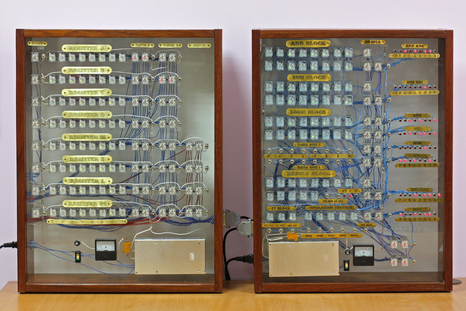
It has now become clear that the computer will consist of 4 blocks: ALU , a register file, a control block, a memory block and peripherals.
The register block is the simplest one - each register has 8 relays for storing bits, a relay for reset and several relays for connecting the register to the bus.

But still, the first I made ALU to deal with the construction of logic circuits on relays. In addition, this immediately led to an 8-bit calculator, which is now sometimes turned on by colleagues (recently, the computer moved to my workplace).
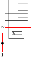
Typically, a relay is not used to store data, but only switches signals. But if you add feedback to his work, then the result can be an RS-trigger. So that once the relay does not turn off, but retains its on state, it is necessary to supply power to the winding through its normally open contacts. When the contacts are closed, this voltage will keep the relay on:
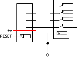
Now, to turn off this relay, you need to break the connection between the power source and the winding. For this, an additional relay is used, which is responsible for resetting the trigger:
Why reset the relay at all? The fact is that the easiest way to write a preset value there is to reset the old one and apply (or not apply) voltage to maintain a new state.
Since the register is always completely reset, the same reset relay is used for all its bits.
The contacts of all switches in the relay responsible for data storage are parallelized. This is done to increase reliability - if one contact fails, current will flow through the other.
Initially, I planned that the address bus on the computer would be 12-bit. So you can easily split the entire address space into several 8-bit groups and connect different devices to them. In this case, address arithmetic will be simplified to 8-bit (almost like working with memory segments in 8086).
Therefore, in the register file there were 2 types of registers - 4 pieces of 8-bit GPR, 2 pieces of “segment” 4 bits each and 2 pieces with offsets of 8 bits. At the same time, from “segment” and “offsets”, it was possible to form 2 full addresses, since the registers were stacked in fixed pairs, such as HL, DE or BC in Z80. But at the same time, any of the registers could be used as an input or output of ALU.
The changes began when I “suddenly” made segment registers 8-bit. This didn’t fundamentally change the architecture (the address bus remained 12-bit), but it provided more opportunities for calculations.
Then I figured that even a simple summation of 256 memory cells would take several tens of minutes. So I decided to narrow the address bus to 8 bits. Because of this, the command system is greatly simplified:
Thanks to all this, the control module circuit has also become easier. The number of relays that will be required for it has greatly decreased. Including due to the fact that you do not need to separately implement the instruction counter (since it moved to the register module in the form of an almost normal register).
As a result, it turned out something similar to the Thumb mode of the ARM processor, only even easier - 8 registers of 8 bits. One register serves as the return address, and the other as the instruction counter. Any case can be used as any of the command arguments.
The only exception is that only 4 out of 8 registers can be used as addresses for reading (or writing) from memory.
The bus to which the registers are connected turned out to be 3 pieces - 2 for transmitting data (for example, an instruction code or ALU operands) and one for transmitting the address.
The hardest thing (or rather, tiring) was to make plates with the names of the registers. Last time I ordered a laser engraving. But the devices used for this have a very small work area and this was not enough for my plates. Therefore, I took up photolithography. For a long time I learned to stick / spray, exhibit and exhibit photoresist, until at least something acceptable turned out. The ideal is still far, but this is not the last block in the computer.

I did not embed toggle switches for loading values into registers in this block. After all, the register module can immediately be connected to the ALU and use its toggle switches already.
Another feature of this module is that it does not have additional LEDs for displaying signals. All stored data can be observed using the control LEDs built into the relay. Therefore, to remove the dump of registers, it is enough to have a camera.

Today, two blocks of the future computer are already working for me - a register file and ALU. But both of them are controlled by external signals and therefore can only perform calculations in calculator mode. The case for the control module is almost ready, so soon it will be possible to start running circuits that make ticking sounds on their own.
Due to the fact that I refused paired registers, the need for a doubled data bus disappeared.
Now it really is needed only in one place - when fetching instructions. The size of all instructions is 16 bits, so a 16-bit bus is needed to download the entire instruction code in one clock cycle. To connect the second argument to ALU, one could use the address bus. Due to this, it would be possible to save 8 relays in the block of registers (and, possibly, a couple more in the control block).
To fix the sign plates, I used bolts for a Phillips screwdriver, as the old-school version is over for me. Does anyone know where you can get brass bolts with a straight slot? Last time I bought them at a hobby-goods store in Helsinki. But it’s quite expensive, and again I won’t get there in the near future.
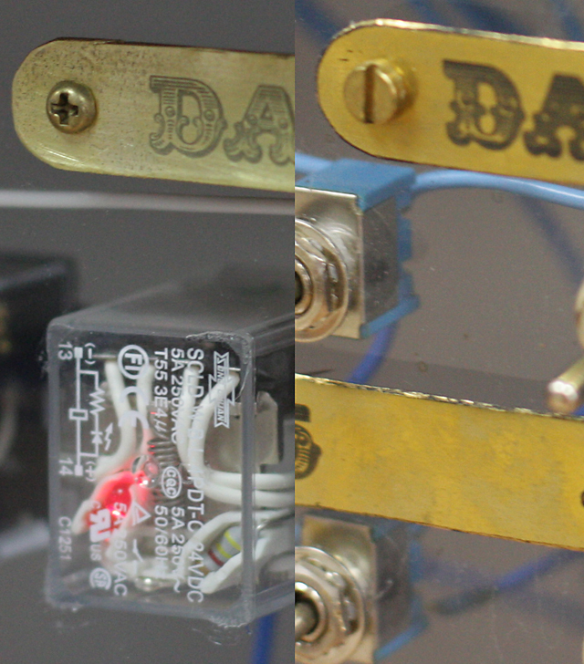
Still need to somehow improve the negative mask printed on a laser printer. Now the black-flooded fields are a bit transparent. Therefore, on some tablets, small dots appeared due to this. Maybe someone knows how to defeat this?
In the next video, a working prototype of a clock generator. I’ll likely increase the frequency a bit to get about 5 beats per second.
Project page on github: github.com/Dovgalyuk/Relay
It has now become clear that the computer will consist of 4 blocks: ALU , a register file, a control block, a memory block and peripherals.
The register block is the simplest one - each register has 8 relays for storing bits, a relay for reset and several relays for connecting the register to the bus.
But still, the first I made ALU to deal with the construction of logic circuits on relays. In addition, this immediately led to an 8-bit calculator, which is now sometimes turned on by colleagues (recently, the computer moved to my workplace).
How a relay saves data
Typically, a relay is not used to store data, but only switches signals. But if you add feedback to his work, then the result can be an RS-trigger. So that once the relay does not turn off, but retains its on state, it is necessary to supply power to the winding through its normally open contacts. When the contacts are closed, this voltage will keep the relay on:
Now, to turn off this relay, you need to break the connection between the power source and the winding. For this, an additional relay is used, which is responsible for resetting the trigger:
Why reset the relay at all? The fact is that the easiest way to write a preset value there is to reset the old one and apply (or not apply) voltage to maintain a new state.
Since the register is always completely reset, the same reset relay is used for all its bits.
The contacts of all switches in the relay responsible for data storage are parallelized. This is done to increase reliability - if one contact fails, current will flow through the other.
Computer architecture
Initially, I planned that the address bus on the computer would be 12-bit. So you can easily split the entire address space into several 8-bit groups and connect different devices to them. In this case, address arithmetic will be simplified to 8-bit (almost like working with memory segments in 8086).
Therefore, in the register file there were 2 types of registers - 4 pieces of 8-bit GPR, 2 pieces of “segment” 4 bits each and 2 pieces with offsets of 8 bits. At the same time, from “segment” and “offsets”, it was possible to form 2 full addresses, since the registers were stacked in fixed pairs, such as HL, DE or BC in Z80. But at the same time, any of the registers could be used as an input or output of ALU.
The changes began when I “suddenly” made segment registers 8-bit. This didn’t fundamentally change the architecture (the address bus remained 12-bit), but it provided more opportunities for calculations.
Then I figured that even a simple summation of 256 memory cells would take several tens of minutes. So I decided to narrow the address bus to 8 bits. Because of this, the command system is greatly simplified:
- The need for separate commands of a 12-bit increment, 12-bit transfer, 12-bit value loading disappeared.
- The jump, subroutine call, and 8-bit value load commands were combined into one with slight differences.
As a side effect, the load value command has the ability to conditionally execute. - Commands with memory have options with a direct address value
Thanks to all this, the control module circuit has also become easier. The number of relays that will be required for it has greatly decreased. Including due to the fact that you do not need to separately implement the instruction counter (since it moved to the register module in the form of an almost normal register).
As a result, it turned out something similar to the Thumb mode of the ARM processor, only even easier - 8 registers of 8 bits. One register serves as the return address, and the other as the instruction counter. Any case can be used as any of the command arguments.
The only exception is that only 4 out of 8 registers can be used as addresses for reading (or writing) from memory.
The bus to which the registers are connected turned out to be 3 pieces - 2 for transmitting data (for example, an instruction code or ALU operands) and one for transmitting the address.
Design
The hardest thing (or rather, tiring) was to make plates with the names of the registers. Last time I ordered a laser engraving. But the devices used for this have a very small work area and this was not enough for my plates. Therefore, I took up photolithography. For a long time I learned to stick / spray, exhibit and exhibit photoresist, until at least something acceptable turned out. The ideal is still far, but this is not the last block in the computer.
I did not embed toggle switches for loading values into registers in this block. After all, the register module can immediately be connected to the ALU and use its toggle switches already.
Another feature of this module is that it does not have additional LEDs for displaying signals. All stored data can be observed using the control LEDs built into the relay. Therefore, to remove the dump of registers, it is enough to have a camera.
Today, two blocks of the future computer are already working for me - a register file and ALU. But both of them are controlled by external signals and therefore can only perform calculations in calculator mode. The case for the control module is almost ready, so soon it will be possible to start running circuits that make ticking sounds on their own.
What could be done better
Due to the fact that I refused paired registers, the need for a doubled data bus disappeared.
Now it really is needed only in one place - when fetching instructions. The size of all instructions is 16 bits, so a 16-bit bus is needed to download the entire instruction code in one clock cycle. To connect the second argument to ALU, one could use the address bus. Due to this, it would be possible to save 8 relays in the block of registers (and, possibly, a couple more in the control block).
To fix the sign plates, I used bolts for a Phillips screwdriver, as the old-school version is over for me. Does anyone know where you can get brass bolts with a straight slot? Last time I bought them at a hobby-goods store in Helsinki. But it’s quite expensive, and again I won’t get there in the near future.
Still need to somehow improve the negative mask printed on a laser printer. Now the black-flooded fields are a bit transparent. Therefore, on some tablets, small dots appeared due to this. Maybe someone knows how to defeat this?
Bonus
In the next video, a working prototype of a clock generator. I’ll likely increase the frequency a bit to get about 5 beats per second.
Project page on github: github.com/Dovgalyuk/Relay