USB MIDI Controller on Arduino

Once again, playing the guitar and controlling the sound through Peavey ReValver and other Amplitube, I thought about purchasing a MIDI controller. Branded devices, such as Guitar Rig Kontrol 3, cost about 13,000 rubles, and have only floor-mounted performance. That is, quickly changing the position of several regulators is very problematic.
Various DJ directional controllers looked more interesting due to the abundance of faders and encoders. It was decided to combine business with pleasure and make the MIDI controller yourself.
Initial requirements: 2-7 faders, the same number of rotary potentiometers / encoders, about 10 buttons, USB connection.
Then he began to choose components. Arduino chose because of availability, in principle, you can use the same ATmega32u4, STM, or another controller. Faders and buttons found at your local radio store. Encoder and potentiometers were once purchased. Tumblers found in the garage. The case decided to make from the top cover of the DVD player.
Accessories:
- Arduino UNO R3 1 pc.
- Faders sp3-25a 5 pcs.
- Mouth. potentiometers 3 pcs.
- Encoder 1 pc.
- Buttons pbs-26b 16 pcs.
- DVD cover 1 pc.
- Toggle switches 2pcs.
First, he bent the case and sawed holes for the faders in it with a drill:

Then he drilled holes for the toggle switches and mouth. potentiometers, marked the position of the buttons. Since I did not have drills at 19 (and the corresponding cartridge for a drill), I drilled holes for buttons at 13, and then increased them with a scan.

The base is ready, now you can think about how to connect all this stuff to the Arduino. While studying this issue, I came across a wonderful HIDUINO project . This is the firmware for the ATmega16u2 on board the Arduino, thanks to which the device is identified as a USB-HID MIDI device. We can only send MIDI data via UART at a speed of 31250 baud. In order not to litter the source code with defines with MIDI event codes, I used this library .
Since I used Arduino, I decided to make a shield, to which all peripherals will already be connected.
Scheme of the shield:
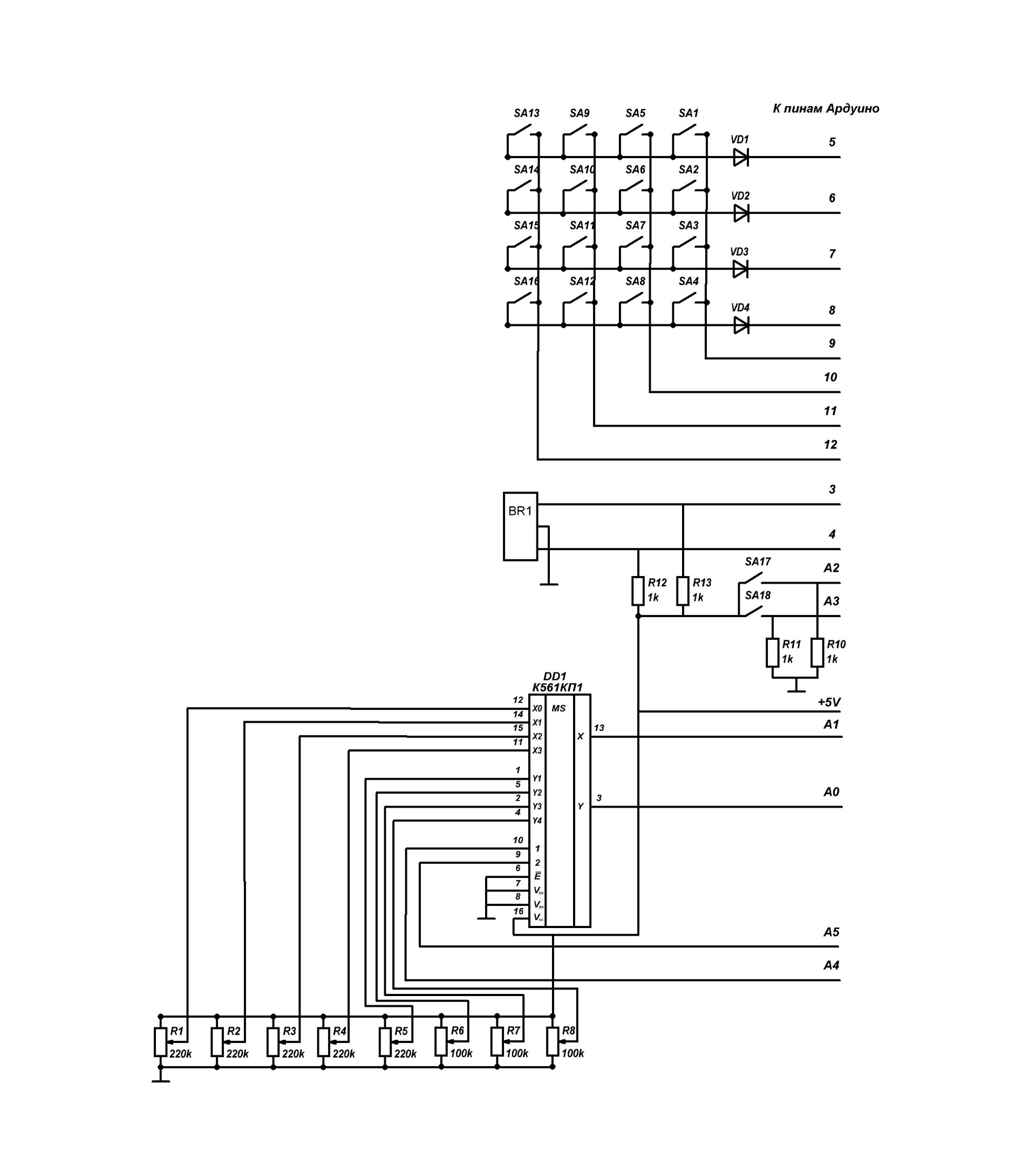
As can be seen from the circuit, the buttons are connected according to the matrix scheme. The built-in pull-up resistors ATmega328 are involved, so the logic is inverse.
Button Initialization
for(byte i = 0; i < COLS; i++){      //--Конфигурируем строки мтрчн клвтр как выходы
        pinMode(colPins[i], OUTPUT);     //--подаём на них лог. 1
        digitalWrite(colPins[i], HIGH);
      }
    for(byte i = 0; i < ROWS; i++){      //--Конфигурируем столбцы мтрчн клвтр как входы---------
        pinMode(rowPins[i], INPUT);      //--включаем встроенные в мк подтягивающие резисторы--
        digitalWrite(rowPins[i], HIGH);
      }
Reading values
for(byte i = 0; i < COLS; i++)                                                                    //-Цикл чтения матричной клавиатуры-----
    {
      digitalWrite(colPins[i], LOW);                                                                //--На считываемый столбец выставляем 0---for(byte j = 0; j < ROWS; j++)                                                                //--Построчно считываем каждый столбец--
        {                                                                                           //--И при нажатой кнопке передаём ноту--
          dval=digitalRead(rowPins[j]);
          if ( dval == LOW && buttonState[i][j] == HIGH ) MIDI.sendNoteOn(kpdNote[j][i],127,1);
          if ( dval == HIGH && buttonState[i][j] == LOW ) MIDI.sendNoteOff(kpdNote[j][i],127,1);
          buttonState[i][j] = dval;
        }
       digitalWrite(colPins[i], HIGH);
    }
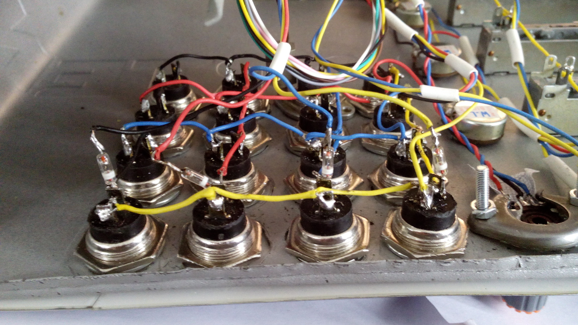
I forgot to put diodes on the signet, I had to solder to the buttons.
Potentiometers are connected through a 4052b multiplexer to the ADC inputs.
Reading potentiometer positions
for(byte chn = 0; chn < 4; chn++)        //-Цикл чтения значений потенциометров
   {
     set_mp_chn(chn);                      //--Задаём параметры мультиплексора
     val=analogRead(0) / 8;                //--Считываем значение с канала Xif (abs(val-PrVal[chn]) > 5)          //--Если текущее значение отл. от прошлого
       {                                   //--больше чем на 5, то посылаем новое значение
       MIDI.sendControlChange(chn,val,1);
       PrVal[chn]=val;
       }
     val=analogRead(1) / 8;                //--Считываем значение с канала Y аналогично Xif (abs(val-PrVal[chn+4]) > 5)
       {
       MIDI.sendControlChange(chn+4,val,1);
       PrVal[chn+4]=val;
       }
   }
The encoder hung on a hardware interrupt.
Encoder reading
voidenc()// Обработка энкодера{
  currenttime=millis();
  if (abs(ltime-currenttime)>50) //  антидребезг
   {
    b=digitalRead(4);
    if (b == HIGH && eval<=122) eval=eval+5;
      elseif (b == LOW && eval>=5) eval=eval-5;
    MIDI.sendControlChange(9,eval,1);
    ltime = millis();
   }
}
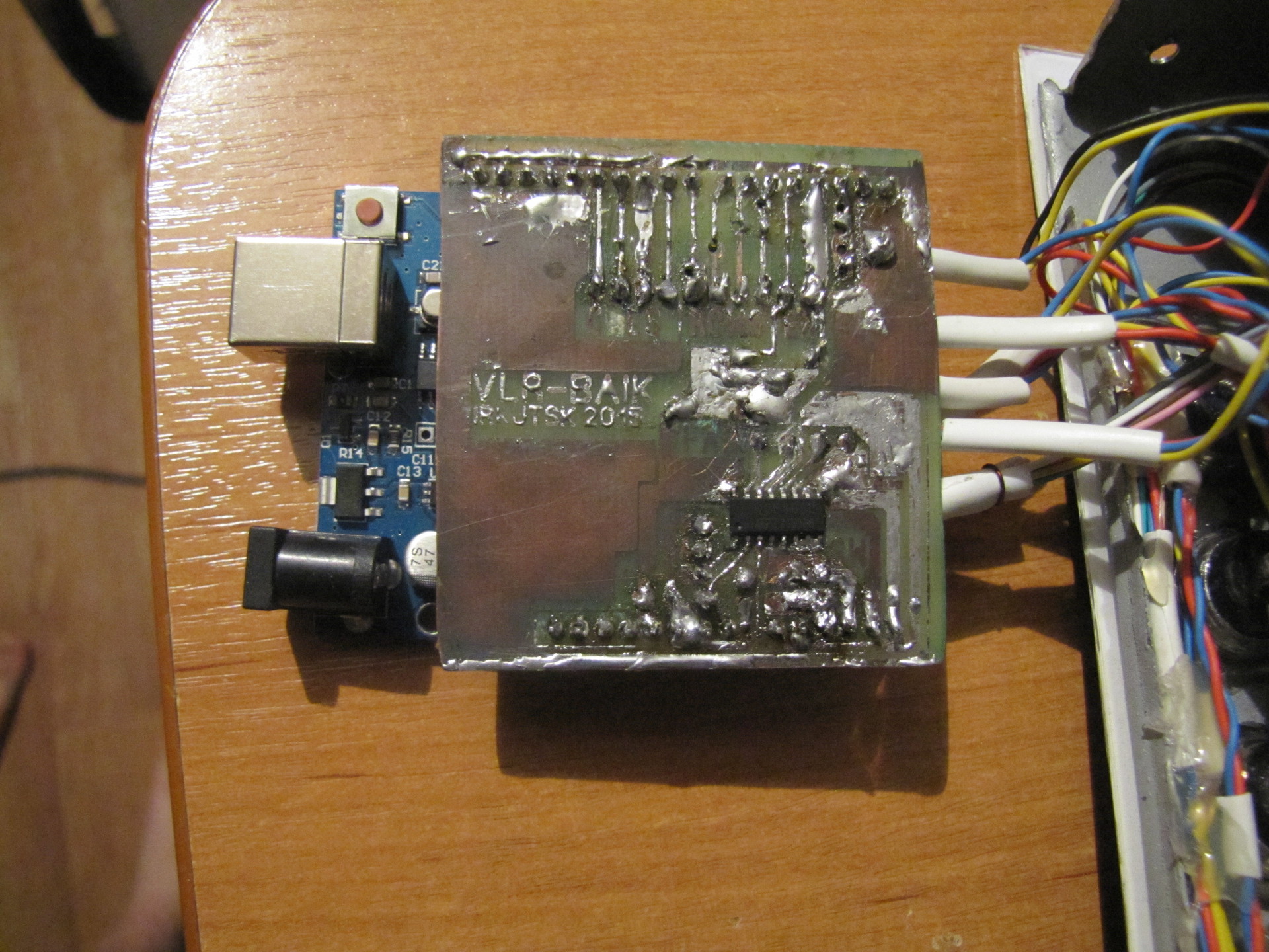
I printed the circuit board in the Sprint layout, then made it with the good old LUT'om using a self-adhesive film and ferric chloride. Solder quality suffers from terrible solder.
Ready shield:

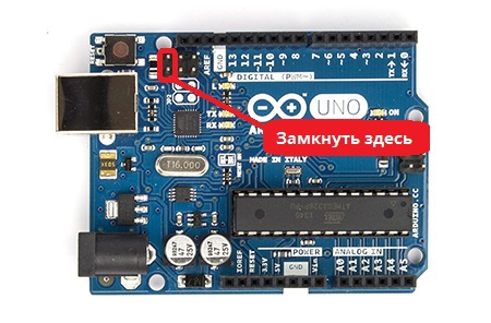
To upload firmware to ATmega32u4, I briefly shorted 2 pins of ICSP, then I used Flip . Later I connected a button to these pins.
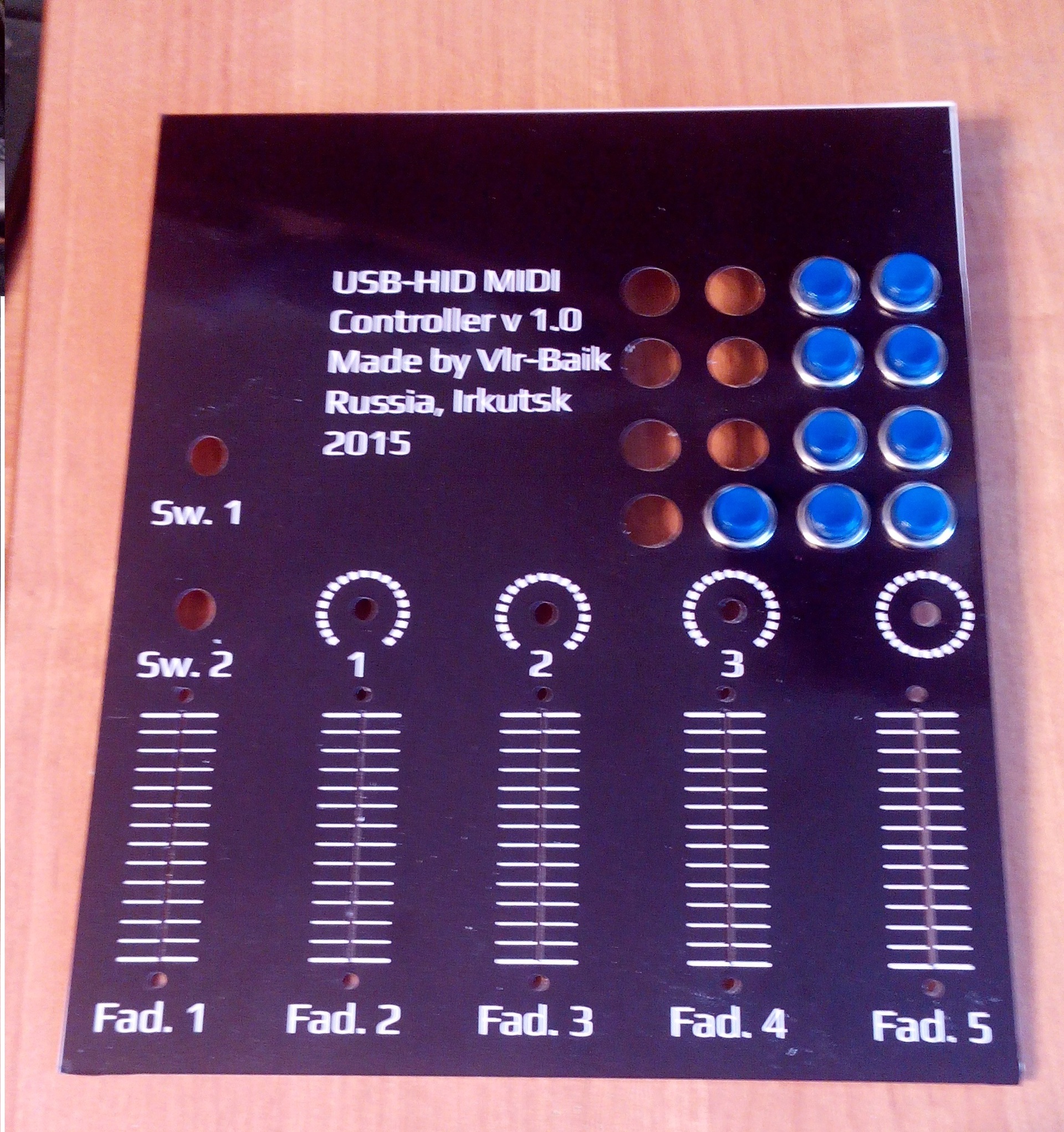
The firmware works, it remains to fasten the walls and front panel. Since I marked everything out in place, it took more to draw a time bar than anything else. It looked like this:
- 1. Graph paper was set as the background of the picture
- 2. Marked holes
- 3. The resulting print
- 4. Cut out all the holes
- 5. Unscrew and remove all elements
- 6. The panel was installed, all buttons / potentiometers were installed in place
- 7. There were inconsistencies between the template and the case
- 8. Go to step 2 until all holes match.
The panel is made of millimeter PET coated with a film with print and lamination, the holes were cut by a laser using a cdr file. For Irkutsk advertisers all this cost me only 240 rubles.
Sawed side walls from plywood.
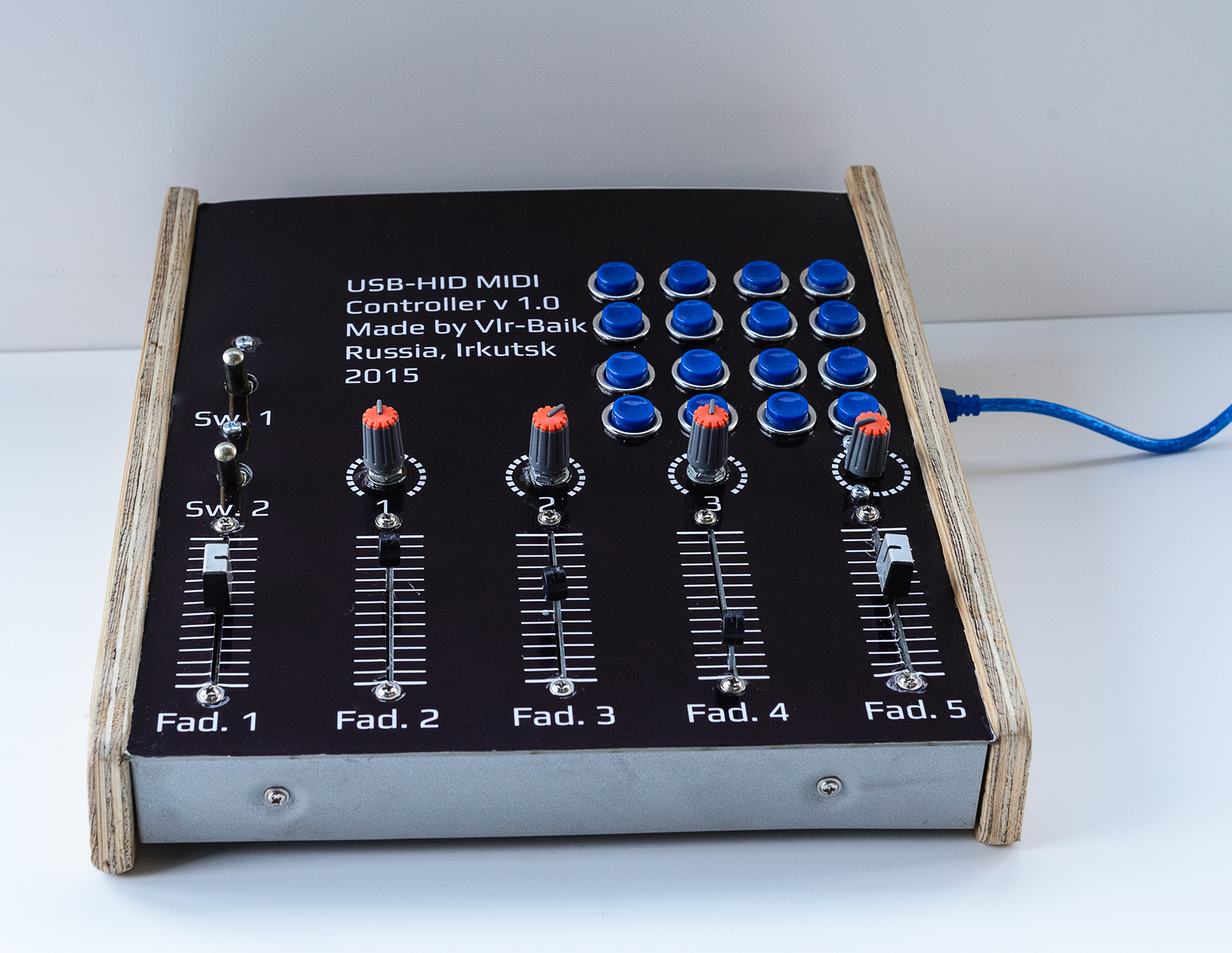
Type of device at the moment:

Cost of accessories:
- Arduino UNO R3 320 p.
- Faders sp3-25a 5x9 = 45 p.
- Mouth. potentiometers + handles 85 p.
- Encoder 15 p.
- Buttons pbs-26b 16x19 = 304 p.
- Panel 240 p.
- Multiplexer 16 p.
- Plywood, textolite, toggle switch, DVD case - in my case, for free.
Total: 1025 rub.
The controller copes with the tasks assigned to it and controls the sound in almost any audio processing program.
It is planned to cover the plywood with stain and cut out the bottom cover from plexiglass. Also add an expansion port for connecting a floor controller.
Code for Arduino and signet on github: https://github.com/vlr-baik/MyMidi